2011 SUBARU IMPREZA WRX STI lock
[x] Cancel search: lockPage 269 of 459

Black plate (273,1)
北米Model "A1110BE-C" EDITED: 2010/ 12/ 17
1. To open the fuel filler lid, pull the lid
release lever up. The lever is on the floor
at the left of the driver ’s seat.
WARNING
Before opening the fuel filler cap,
first touch the vehicle body or a
metal portion of the fuel pump or
similar object to discharge any
static electricity that may be present
on your body. If your body is carry-
ing an electrostatic charge, there is
a possibility that an electric spark
could ignite the fuel, which could
burn you. To avoid acquiring a new
static electric charge, do not get
back into the vehicle while refueling
is in progress.1) Open
2) Close2. Remove the fuel filler cap by turning it slowly counterclockwise.
WARNING
.
Gasoline vapor is highly flam-
mable. Before refueling, always
first stop the engine and close all
vehicle doors and windows.
Make sure that there are no
lighted cigarettes, open flames
or electrical sparks in the adja-
cent area. Only handle fuel out-
doors. Quickly wipe up any
spilled fuel.
. When opening the cap, grasp it
firmly and turn it slowly to the
left. Do not remove the cap
quickly. Fuel may be under pres-
sure and spray out of the fuel
filler neck, especially in hot
weather. If you hear a hissing
sound while you are removing
the cap, wait for the sound to
stop and then slowly open the
cap to prevent fuel from spraying
out and creating a fire hazard.
Starting and operating
7-5
– CONTINUED –
7
Page 270 of 459
Black plate (274,1)
北米Model "A1110BE-C" EDITED: 2010/ 12/ 17
7-6
Starting and operating
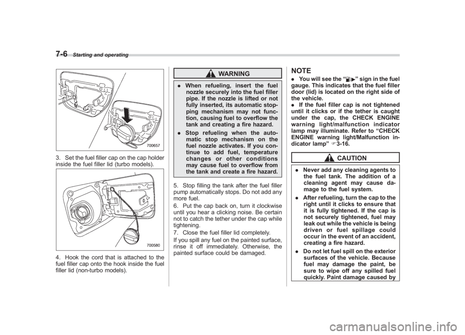
3. Set the fuel filler cap on the cap holder
inside the fuel filler lid (turbo models).4. Hook the cord that is attached to the
fuel filler cap onto the hook inside the fuel
filler lid (non-turbo models).
WARNING
. When refueling, insert the fuel
nozzle securely into the fuel filler
pipe. If the nozzle is lifted or not
fully inserted, its automatic stop-
ping mechanism may not func-
tion, causing fuel to overflow the
tank and creating a fire hazard.
. Stop refueling when the auto-
matic stop mechanism on the
fuel nozzle activates. If you con-
tinue to add fuel, temperature
changes or other conditions
may cause fuel to overflow from
the tank and create a fire hazard.
5. Stop filling the tank after the fuel filler
pump automatically stops. Do not add any
more fuel.
6. Put the cap back on, turn it clockwise
until you hear a clicking noise. Be certain
not to catch the tether under the cap while
tightening.
7. Close the fuel filler lid completely.
If you spill any fuel on the painted surface,
rinse it off immediately. Otherwise, the
painted surface could be damaged.
NOTE. You will see the “
”sign in the fuel
gauge. This indicates that the fuel filler
door (lid) is located on the right side of
the vehicle.
. If the fuel filler cap is not tightened
until it clicks or if the tether is caught
under the cap, the CHECK ENGINE
warning light/malfunction indicator
lamp may illuminate. Refer to “CHECK
ENGINE warning light/Malfunction in-
dicator lamp ”F 3-16.
CAUTION
. Never add any cleaning agents to
the fuel tank. The addition of a
cleaning agent may cause da-
mage to the fuel system.
. After refueling, turn the cap to the
right until it clicks to ensure that
it is fully tightened. If the cap is
not securely tightened, fuel may
leak out while the vehicle is being
driven or fuel spillage could
occur in the event of an accident,
creating a fire hazard.
. Do not let fuel spill on the exterior
surfaces of the vehicle. Because
fuel may damage the paint, be
sure to wipe off any spilled fuel
quickly. Paint damage caused by
Page 274 of 459
Black plate (278,1)
北米Model "A1110BE-C" EDITED: 2010/ 12/ 17
7-10
Starting and operating
position and check the operation of the
warning and indicator lights. Refer to
“Warning and indicator lights ”F 3-13.
5. Turn the ignition switch to the “START”
position without depressing the accelera-
tor pedal. Release the key immediately
after the engine has started.
If the engine does not start, try the
following.
(1) Turn the ignition switch to the
“OFF ”position and wait for at least
10 seconds. After checking that the
parking brake is firmly set, turn the
ignition switch to the “START”position
while depressing the accelerator pedal
slightly (approximately a quarter of the
full stroke). Release the accelerator
pedal as soon as the engine starts.
(2) If this fails to start the engine, turn
the ignition switch back to the “OFF”
position and wait for at least 10
seconds. Then fully depress the accel-
erator pedal and turn the ignition
switch to the “START”position. If the
engine starts, quickly release the
accelerator pedal.
(3) If this fails to start the engine, turn
the ignition switch again to the “OFF”
position. After waiting for 10 seconds
or longer, turn the ignition switch to the
“START ”position without depressing
the accelerator pedal. (4) If the engine still refuses to start,
contact your nearest SUBARU dealer
for assistance.
6. Confirm that all warning and indicator
lights have turned off after the engine has
started. The fuel injection system auto-
matically lowers the idle speed as the
engine warms up.
While the engine is warming up, make
sure that the select lever is at the “P”or
“N ”position and that the parking brake is
applied.
CAUTION
If you restart the engine while the
vehicle is moving, shift the select
lever into the “N ” position. Do not
attempt to place the select lever of a
moving vehicle into the “P ” posi-
tion.
Stopping the engineThe ignition switch should be turned off
only when the vehicle is stopped and the
engine is idling.
WARNING
Do not stop the engine when the
vehicle is moving. This will cause
loss of power to the power steering
and the brake booster, making steer-
ing and braking more difficult. It
could also result in accidental acti-
vation of the “LOCK ”position on the
ignition switch, causing the steering
wheel to lock.
Page 276 of 459
Black plate (280,1)
北米Model "A1110BE-C" EDITED: 2010/ 12/ 17
7-12
Starting and operating
& Entering the vehicle while it
is running via remote start1. Unlock the vehicle doors using the
remote keyless entry system. If the vehi-
cle’s doors are unlocked manually using
the key, the vehicle’ s alarm system will
trigger and the remote engine start system
will turn off. Inserting the key into the
ignition switch and turning it to the “ON”
position or pressing the unlock button “
”
on the remote keyless entry transmitter
will disarm the alarm system. Refer to
“Alarm system ”F 2-16.
2. Enter the vehicle. Do not depress the
brake pedal.
3. Insert the key into the ignition switch
and turn to the “ON ”position. If the ignition
switch is accidentally turned to the
“START ”position, the system ’s “starter
anti-grind ”feature will prevent the starter
from re-cranking.
4. Depress the brake pedal. The remote
starter disengages, the vehicle’ s power
window features are re-enabled and the
vehicle will operate normally.
& Entering the vehicle follow-
ing remote engine start shut-
downAn alarm trigger may occur if the vehicle is
opened by the remote keyless entry transmitter within a few seconds immedi-
ately following remote engine start shut-
down.
&
Pre-heating or pre-cooling
the interior of the vehicleBefore exiting the vehicle, set the tem-
perature controls to the desired setting
and operation. After the system starts the
vehicle, the heater or air-conditioning will
activate and heat or cool the interior to
your setting.&Service modeIn service mode, the remote start function
is temporarily disabled to prevent the
system from unexpectedly starting the
engine while being serviced.
! To engage the service mode
Turn the ignition switch to the “ON ”
position, depress and hold the brake
pedal, then press and release the “
”
button on the remote engine start trans-
mitter three times. The system will pause
for 1 second and then flash the turn signal
lights and honk the horn three times
indicating that the system is in service
mode. When attempting to activate the
remote start system while in service
mode, the turn signal lights will flash and
the horn will honk two times and will not start.
!
To disengage the service mode
Turntheignitionswitchtothe “ON ”
position, depress and hold the brake
pedal, then press and release the “
”
button on the remote engine start trans-
mitter three times. The system will pause
for 1 second and flash the turn signal
lights once indicating that the system has
exited service mode.
NOTEWhen taking your vehicle in for service,
it is recommended that you inform the
service personnel that your vehicle is
equipped with a remote engine start
system.& Remote engine start trans-
mitter programming and pro-
grammable feature optionNew transmitters can be programmed to
the remote engine start system in the
event that remote engine start transmitters
are lost, stolen or damaged. The remote
engine start system also has one pro-
grammable feature that can be adjusted
for user preference.
The remote engine start system can be
programmed to either make an audible
horn chirp upon remote start activation or
Page 277 of 459

Black plate (281,1)
北米Model "A1110BE-C" EDITED: 2010/ 12/ 17
not. Remote engine start transmitter pro-
gramming and feature programming can
be adjusted using the following procedure.
1. Open the driver ’s door (the driver ’s
door must remain opened throughout the
entire process).
2. Insert the key into the vehicle ’s ignition
switch and turn to the “ON”position.
3. Locate the small black programming
button behind the fuse box cover, on the
driver ’s side left under the dashboard
panel.
4. Press and hold the black programming
button for 10 to 15 seconds. The horn will
honk and the turn signal lights will flash
three times to indicate that the system has
entered programming mode. At this point
you can proceed to either step 5 or step 6.
5. To program a remote engine start
transmitter: press and release the “
”
button on each transmitter. The horn will
honk and the turn signal lights will flash
one time to indicate a successful trans-
mitter learn each time the “
”button is
pressed. You can program up to eight
transmitters.
6. To toggle the Horn Confirmation chirps
ON/OFF: depress and release the brake
pedal to toggle the feature. The horn will
chirp and the turn signal lights will flash
one time to indicate Confirmation Horn
Chirps are “OFF”. The horn will honk and the turn signal lights will flash 2 times to
indicate Confirmation Horn Chirps are
“ON
”. Depressing the brake pedal repeat-
edly will toggle the feature ON or OFF
each time.
7. To exit the remote engine start trans-
mitter and feature programming mode,
turn the ignition switch to the “LOCK”
position, remove the key from the ignition
switch and test operation of the remote
engine start transmitter(s) and horn con-
firmation feature.
& System maintenance! Changing the batteries
CAUTION
.Do not let dust, oil or water get on
or in the remote engine start
transmitter when replacing the
battery.
. Be careful not to damage the
printed circuit board in the re-
mote engine start transmitter
when replacing the battery.
. Be careful not to allow children to
touch the battery and any re-
moved parts; children could
swallow them.
. There is a danger of explosion if an incorrect replacement battery
is used. Replace only with the
same or equivalent type of bat-
tery.
. Batteries should not be exposed
to excessive heat such as sun-
shine, fire or the like.
The two 3-volt lithium batteries (model
CR-1220 ) supplied in your remote engine
start transmitter should last approximately
3 years, depending on usage. When the
batteries begin to weaken, you will notice
a decrease in range (distance from the
vehicle that your remote engine start
system operates). Follow the instructions
below to change the remote engine start
transmitter batteries.
Starting and operating
7-13
– CONTINUED –
7
Page 280 of 459
Black plate (284,1)
北米Model "A1110BE-C" EDITED: 2010/ 12/ 17
7-16
Starting and operating
the vehicle is moving.& Shifting speeds! Recommended shifting speeds
The best compromise between fuel econ-
omy and vehicle performance during
normal driving is ensured by shifting up
at the speeds listed in the following table.
Shift up mph (km/h)
1st to 2nd 15 (24)
2nd to 3rd 25 (40)
3rd to 4th 40 (64)
4th to 5th 45 (72)
5th to 6th 50 (80)
!Maximum allowable speeds
The following table shows the maximum
speeds that are possible with each differ-
ent gear. The tachometer ’s needle will
enter the red area if these speeds are
exceeded.
With the exception of cases where sudden
acceleration is required, the vehicle
should not be driven with the tachometer ’s
needle inside the red area. Failure to
observe this precaution can lead to
excessive engine wear and poor fuel economy.
Gear
mph (km/h)
1st 31 (50)
2nd 50 (81)
3rd 74 (119)
4th 99 (159)
WARNING
When shifting down a gear, ensure
that the vehicle is not travelling at a
speed exceeding the Maximum Al-
lowable Speed for the gear which is
about to be selected. Failure to
observe this precaution can lead to
engine over-revving and this in turn
can result in engine damage.
In addition, sudden application of
engine brakes when the vehicle is
travelling on a slippery surface can
lead to wheel locking; as a conse-
quence, control of the vehicle may
be lost and the risk of an accident
increased.NOTENever exceed posted speed limits.
&Driving tipsDo not drive with your foot resting on the
clutch pedal and do not use the clutch to
hold your vehicle at a standstill on an
upgrade. Either of those actions may
cause clutch damage.
Do not drive with your hand resting on the
shift lever. This may cause wear on the
transmission components.
When it is necessary to reduce vehicle
speed due to slow traffic, turning corners,
or driving up steep hills, downshift to a
lower gear before the engine starts to
labor.
On steep downgrades, downshift the
transmission to 5th, 4th, 3rd or 2nd gear
as necessary; this helps to maintain a safe
speed and to extend brake pad life.
In this way, the engine provides a braking
effect. Remember, if you “ride”(over use)
the brakes while descending a hill, they
may overheat and not work properly.
The engine may, on rare occasions, knock
when the vehicle rapidly accelerates or
rapidly pulls away from a standstill. This
phenomenon does not indicate a malfunc-
tion.
Page 282 of 459
Black plate (286,1)
北米Model "A1110BE-C" EDITED: 2010/ 12/ 17
7-18
Starting and operating
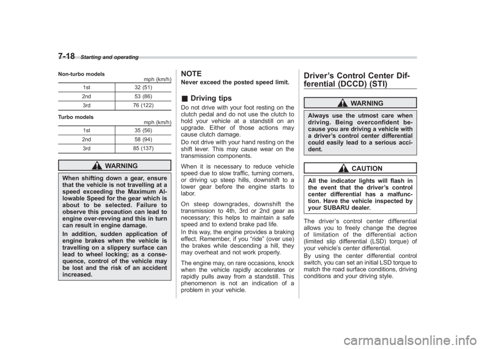
Non-turbo models
mph (km/h)
1st 32 (51)
2nd 53 (86)
3rd 76 (122)
Turbo models mph (km/h)
1st 35 (56)
2nd 58 (94)
3rd 85 (137)
WARNING
When shifting down a gear, ensure
that the vehicle is not travelling at a
speed exceeding the Maximum Al-
lowable Speed for the gear which is
about to be selected. Failure to
observe this precaution can lead to
engine over-revving and this in turn
can result in engine damage.
In addition, sudden application of
engine brakes when the vehicle is
travelling on a slippery surface can
lead to wheel locking; as a conse-
quence, control of the vehicle may
be lost and the risk of an accident
increased.
NOTENever exceed the posted speed limit.&
Driving tipsDo not drive with your foot resting on the
clutch pedal and do not use the clutch to
hold your vehicle at a standstill on an
upgrade. Either of those actions may
cause clutch damage.
Do not drive with your hand resting on the
shift lever. This may cause wear on the
transmission components.
When it is necessary to reduce vehicle
speed due to slow traffic, turning corners,
or driving up steep hills, downshift to a
lower gear before the engine starts to
labor.
On steep downgrades, downshift the
transmission to 4th, 3rd or 2nd gear as
necessary; this helps to maintain a safe
speed and to extend brake pad life.
In this way, the engine provides a braking
effect. Remember, if you “ride”(over use)
the brakes while descending a hill, they
may overheat and not work properly.
The engine may, on rare occasions, knock
when the vehicle rapidly accelerates or
rapidly pulls away from a standstill. This
phenomenon is not an indication of a
problem in your vehicle.
Driver ’s Control Center Dif-
ferential (DCCD) (STI)
WARNING
Always use the utmost care when
driving. Being overconfident be-
cause you are driving a vehicle with
a driver ’s control center differential
could easily lead to a serious acci-
dent.
CAUTION
All the indicator lights will flash in
the event that the driver ’s control
center differential has a malfunc-
tion. Have the vehicle inspected by
your SUBARU dealer.
The driver ’s control center differential
allows you to freely change the degree
of limitation of the d ifferential action
(limited slip differential (LSD) torque) of
your vehicle’ s center differential.
By using the center differential control
switch, you can set an initial LSD torque to
match the road surface conditions, driving
conditions and your driving style.
Page 285 of 459
Black plate (289,1)
北米Model "A1110BE-C" EDITED: 2010/ 12/ 17
! Center differential control switch
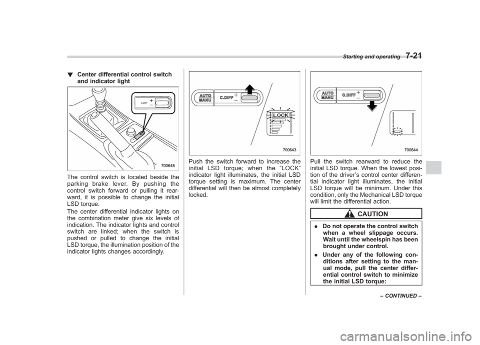
and indicator lightThe control switch is located beside the
parking brake lever. By pushing the
control switch forward or pulling it rear-
ward, it is possible to change the initial
LSD torque.
The center differential indicator lights on
the combination meter give six levels of
indication. The indicator lights and control
switch are linked; when the switch is
pushed or pulled to change the initial
LSD torque, the illumination position of the
indicator lights changes accordingly.
Push the switch forward to increase the
initial LSD torque; when the “LOCK ”
indicator light illuminates, the initial LSD
torque setting is maximum. The center
differential will then be almost completely
locked.
Pull the switch rearward to reduce the
initial LSD torque. When the lowest posi-
tion of the driver ’s control center differen-
tial indicator light illuminates, the initial
LSD torque will be minimum. Under this
condition, only the Mechanical LSD torque
will limit the differential action.
CAUTION
. Do not operate the control switch
when a wheel slippage occurs.
Wait until the wheelspin has been
brought under control.
. Under any of the following con-
ditions after setting to the man-
ual mode, pull the center differ-
ential control switch to minimize
the initial LSD torque:
Starting and operating
7-21
– CONTINUED –
7