2011 SUBARU IMPREZA WRX battery
[x] Cancel search: batteryPage 225 of 458
5-38Audio
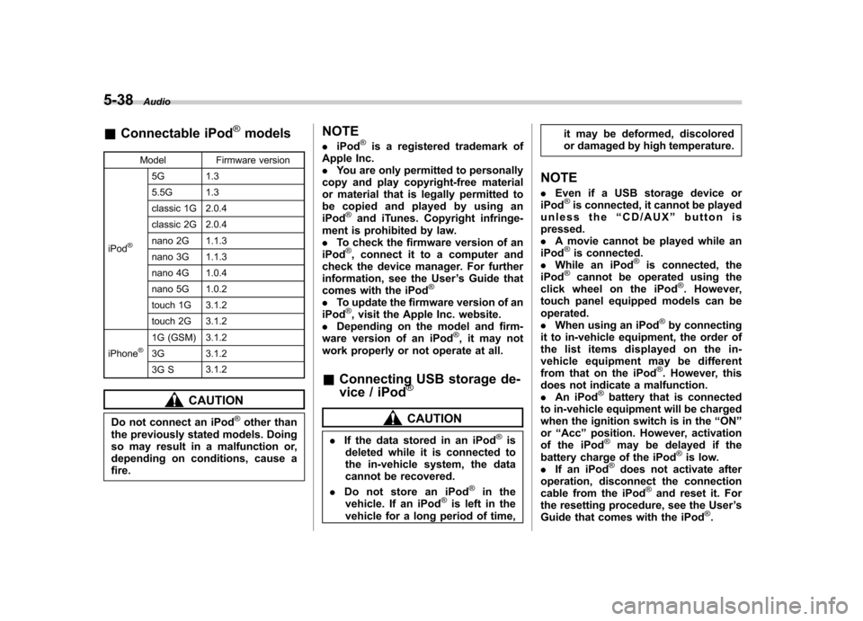
&Connectable iPod®models
Model Firmware version
iPod
®
5G 1.3
5.5G 1.3
classic 1G 2.0.4
classic 2G 2.0.4
nano 2G 1.1.3
nano 3G 1.1.3
nano 4G 1.0.4
nano 5G 1.0.2
touch 1G 3.1.2
touch 2G 3.1.2
iPhone
®1G (GSM) 3.1.2
3G 3.1.2
3G S 3.1.2
CAUTION
Do not connect an iPod
®other than
the previously stated models. Doing
so may result in a malfunction or,
depending on conditions, cause a fire. NOTE .
iPod
®is a registered trademark of
Apple Inc. . You are only permitted to personally
copy and play copyright-free material
or material that is legally permitted to
be copied and played by using aniPod
®and iTunes. Copyright infringe-
ment is prohibited by law.. To check the firmware version of an
iPod
®, connect it to a computer and
check the device manager. For further
information, see the User ’s Guide that
comes with the iPod
®
. To update the firmware version of an
iPod®, visit the Apple Inc. website.
. Depending on the model and firm-
ware version of an iPod
®, it may not
work properly or not operate at all. & Connecting USB storage de-
vice / iPod
®
CAUTION
. If the data stored in an iPod
®is
deleted while it is connected to
the in-vehicle system, the data
cannot be recovered.
. Do not store an iPod
®in the
vehicle. If an iPod®is left in the
vehicle for a long period of time, it may be deformed, discolored
or damaged by high temperature.
NOTE . Even if a USB storage device or
iPod
®is connected, it cannot be played
unless the “CD/AUX ”button is
pressed. . A movie cannot be played while an
iPod
®is connected.
. While an iPod®is connected, the
iPod®cannot be operated using the
click wheel on the iPod®. However,
touch panel equipped models can beoperated.. When using an iPod
®by connecting
it to in-vehicle equipment, the order of
the list items displayed on the in-
vehicle equipment may be different
from that on the iPod
®. However, this
does not indicate a malfunction. . An iPod
®battery that is connected
to in-vehicle equipment will be charged
when the ignition switch is in the “ON ”
or “Acc ”position. However, activation
of the iPod
®may be delayed if the
battery charge of the iPod®is low.
. If an iPod®does not activate after
operation, disconnect the connection
cable from the iPod
®and reset it. For
the resetting procedure, see the User ’s
Guide that comes with the iPod
®.
Page 234 of 458

&Tips for the Hands-free sys- tem
! Bluetooth
®
NOTE
The Bluetooth word mark and logo are
registered trademarks of Bluetooth
SIG, Inc.
It is possible to connect a cell phone to the
in-vehicle equipment through the Blue-
tooth
®format (wireless) to make a phone
call from the in-vehicle equipment or take
an incoming phone call.
Since the Bluetooth
®format is wireless, a
connection between the in-vehicle equip-
ment and the cell phone can be made
without placing them in close proximity of
each other. The cell phone can be used with it left in the breast pocket or bag.
NOTE . The Hands-free system may not
operate properly under the following conditions.
–The cell phone is turned off.
– The cell phone is not in the
phone call area. – The battery of the cell phone has
run down.– The cell phone is not connected
to the Hands-free system.– The cell phone is behind the seat
or in the glove box.– A metal material covers or
touches the cell phone.
. Depending on the type of cell phone
that is used, the screen on the cell
phone may remain illuminated while
the ignition switch is in the “ON ”
position. If this occurs, turn the illumi-
nation off by adjusting the cell phonesettings. . Depending on the setting of the cell
phone, the dial lock function may be
activated after making a call. Deacti-
vate the automatic dial lock function of
the cell phone before using the Hands-
free system. . Depending on the type of cell phone
that is used, operation and the sound volume may be different from those of
cell phones currently used. .
When the ignition switch is turned to
the “LOCK ”position during a call, the
call may be disconnected or continued
on the cell phone depending on the
type of cell phone that is used. Note
that operation of the cell phone may be
necessary if the call is continued on the
cell phone. . Do not speak at the same time as the
other party during a call. If you and the
party speak at the same time, it may be
difficult for the other party to hear your
voice and vice versa. This is normal. . The receiver sound volume should
be set as low as possible. Otherwise,
the party you are calling may notice an
undesirable echo sound. . Speak clearly and loudly.
. Your voice may be difficult to be
heard by the party under the following conditions.
–Driving on a rough road.
– Driving at a high speed.
– Driving with a window open.
– When air from the ventilator
blows directly towards the micro-phone. – When the sound coming from the
ventilator is loud. Audio
5-47
– CONTINUED –
Page 251 of 458
6-2Interior equipment
Interior lights
When leaving your vehicle, make sure the
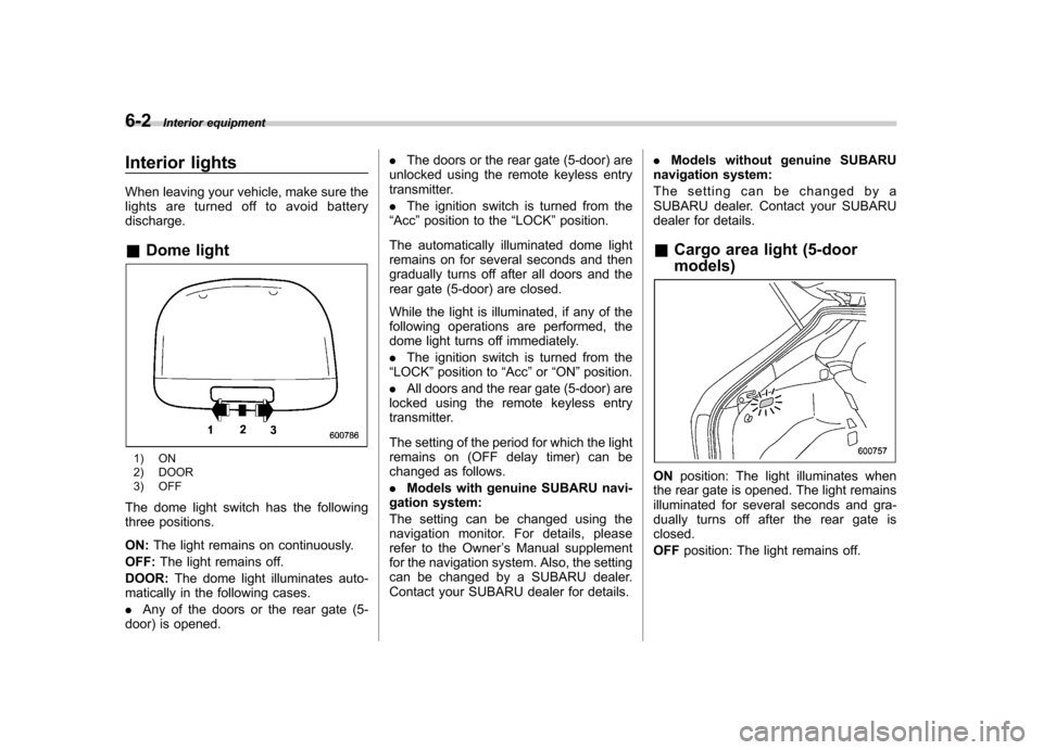
lights are turned off to avoid batterydischarge. &Dome light
1) ON
2) DOOR
3) OFF
The dome light switch has the following
three positions. ON: The light remains on continuously.
OFF: The light remains off.
DOOR: The dome light illuminates auto-
matically in the following cases. . Any of the doors or the rear gate (5-
door) is opened. .
The doors or the rear gate (5-door) are
unlocked using the remote keyless entry
transmitter. . The ignition switch is turned from the
“ Acc ”position to the “LOCK ”position.
The automatically illuminated dome light
remains on for several seconds and then
gradually turns off after all doors and the
rear gate (5-door) are closed.
While the light is illuminated, if any of the
following operations are performed, the
dome light turns off immediately. . The ignition switch is turned from the
“ LOCK ”position to “Acc ”or “ON ”position.
. All doors and the rear gate (5-door) are
locked using the remote keyless entry
transmitter.
The setting of the period for which the light
remains on (OFF delay timer) can be
changed as follows. . Models with genuine SUBARU navi-
gation system:
The setting can be changed using the
navigation monitor. For details, please
refer to the Owner ’s Manual supplement
for the navigation system. Also, the setting
can be changed by a SUBARU dealer.
Contact your SUBARU dealer for details. .
Models without genuine SUBARU
navigation system:
The setting can be changed by a
SUBARU dealer. Contact your SUBARU
dealer for details.
& Cargo area light (5-door models)
ON position: The light illuminates when
the rear gate is opened. The light remains
illuminated for several seconds and gra-
dually turns off after the rear gate isclosed. OFF position: The light remains off.
Page 252 of 458
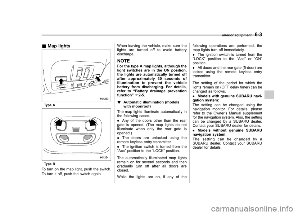
&Map lights
Type A
Type B
To turn on the map light, push the switch.
To turn it off, push the switch again. When leaving the vehicle, make sure the
lights are turned off to avoid batterydischarge.
NOTE
For the type A map lights, although the
light switches are in the ON position,
the lights are automatically turned off
after approximately 30 seconds of
illumination to prevent the vehicle
battery from discharging. For details,
refer to “Battery drainage prevention
function ”F 2-5.
! Automatic illumination (models
with moonroof)
The map lights illuminate automatically in
the following cases. . Any of the doors other than the rear
gate is opened. (The map lights do not
illuminate when only the rear gate isopened.) . The doors are unlocked using the
remote keyless entry transmitter.. The ignition switch is turned from the
“ Acc ”position to the “LOCK ”position.
The automatically illuminated map lights
remain on for several seconds and then
gradually turn off after all doors areclosed.
While the lights are on, if any of the following operations are performed, the
map lights turn off immediately. .
The ignition switch is turned from the
“ LOCK ”position to the “Acc ”or “ON ”
position.. All doors and the rear gate (5-door) are
locked using the remote keyless entry
transmitter.
The setting of the period for which the
lights remain on (OFF delay timer) can be
changed as follows. . Models with genuine SUBARU navi-
gation system:
The setting can be changed using the
navigation monitor. For details, please
refer to the Owner ’s Manual supplement
for the navigation system. Also, the setting
can be changed by a SUBARU dealer.
Contact your SUBARU dealer for details. . Models without genuine SUBARU
navigation system:
The setting can be changed by a
SUBARU dealer. Contact your SUBARU
dealer for details. Interior equipment
6-3
Page 257 of 458
6-8Interior equipment
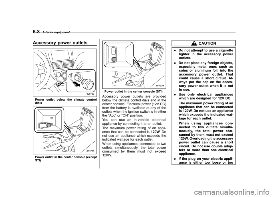
Accessory power outlets
Power outlet below the climate control dials
Power outlet in the center console (except STI)
Power outlet in the center console (STI)
Accessory power outlets are provided
below the climate control dials and in the
center console. Electrical power (12V DC)
from the battery is available at any of the
outlets when the ignition switch is in eitherthe “Acc ”or “ON ”position.
You can use an in-vehicle electrical
appliance by connecting it to an outlet.
The maximum power rating of an appli-
ance that can be connected is 120W.Do
not use an appliance which exceeds the
indicated wattage for each outlet.
When using appliances connected to two
outlets simultaneously, the total power
consumed by them must not exceed
120W.
CAUTION
. Do not attempt to use a cigarette
lighter in the accessory power outlets.
. Do not place any foreign objects,
especially metal ones such as
coins or aluminum foil, into the
accessory power outlet. That
could cause a short circuit. Al-
ways put the cap on the acces-
sory power outlet when it is not
in use.
. Use only electrical appliances
which are designed for 12V DC.
The maximum power rating of an
appliance that can be connected
is 120W. Do not use an appliance
which exceeds the indicated wat-
tage for each outlet.
When using appliances con-
nected to two outlets simulta-
neously, the total power con-
sumed by them must not exceed
120W. Overloading the accessory
power outlet can cause a short
circuit. Do not use double adap-
ters or more than one electricalappliance.
. If the plug on your electric appli-
ance is either too loose or too
Page 258 of 458
tight for the accessory power
outlet, this can result in a poor
contact or cause the plug to get
stuck. Only use plugs that fit
properly.
. Use of an electric appliance in the
accessory power outlet for a long
period of time while the engine is
not running can cause batterydischarge.
. Before driving your vehicle, make
sure that the plug and the cord
on your electrical appliance will
not interfere with your shifting
gears and operating the accel-
erator and brake pedals. If they
do, do not use the electrical
appliance while driving. &
Use with a cigarette lighter (if equipped)
To use the accessory power outlet below
the climate control as a cigarette lighter
socket, purchase the cigarette lighter plug,
which is an optional accessory. A cigarette
lighter plug is available from your
SUBARU dealer.
The cigarette lighter operates only when
the ignition switch is in the “ON ”or “Acc ”
position.
To use the cigarette lighter, push in the
knob and wait a few moments. It will
automatically spring up when ready foruse.
WARNING
To avoid being burned, never grasp
the lighter by the end with the
heating element. Doing so could
result in injury and could also
damage the heating element.
CAUTION
. Do not hold the lighter pushed in,
because it will overheat.
. The electrical power socket lo-
cated in the center console is
originally designed to use a gen- uine SUBARU cigarette lighter
plug. Do not use a non-genuine
cigarette lighter plug in the sock-
et. Doing so may cause a short-
circuit and overheating, resulting
in a fire.
. If the socket is ever used for a
plug-in accessory such as a cell
phone, that may damage the
portion of the socket ’s internal
mechanism that causes a cigar-
ette lighter plug to “pop out ”
after its lighter element is heated.
Therefore, do not place a cigar-
ette lighter plug in a socket that
has been used, even once, to
power a plug-in accessory. Doing
so may cause the plug to stick
and overheat, creating a potential
fire hazard. Interior equipment
6-9
Page 272 of 458

Starting the engine
CAUTION
Do not operate the starter motor
continuously for more than 10 sec-
onds. If the engine fails to start after
operating the starter for 5 to 10
seconds, wait for 10 seconds or
more before trying again.
NOTE . It may be difficult to start the engine
when the battery has been discon-
nected and reconnected (for mainte-
nance or other purposes). This diffi-
culty is caused by the electronically
controlled throttle ’s self-diagnosis
function. To overcome it, keep the
ignition switch in the “ON ”position
for approximately 10 seconds before
starting the engine.. For non-turbo models, to protect the
engine while the shift lever is in the
neutral position (MT models)/select
lever is in the “P ” or “N ” position (AT
models), the engine is controlled so
that the engine speed may not become
too high even if the accelerator pedal is
depressed hard. &
MT models
1. Apply the parking brake.
2. Turn off unnecessary lights and ac- cessories.
3. Depress the clutch pedal to the floor
and shift the shift lever into neutral. Hold
the clutch pedal to the floor while starting
the engine.
The starter motor will only operate when
the clutch pedal is depressed fully to the
floor.
4. Turn the ignition switch to the “ON ”
position and check the operation of the
warning and indicator lights. Refer to“ Warning and indicator lights ”F 3-13.
5. Turn the ignition switch to the “START ”
position without depressing the accelera-
tor pedal. Release the key immediately
after the engine has started.
If the engine does not start, try the following.
(1) Turn the ignition switch to the“OFF ”position and wait for at least
10 seconds. After checking that the
parking brake is firmly set, turn the
ignition switch to the “START ”position
while depressing the accelerator pedal
slightly (approximately a quarter of the
full stroke). Release the accelerator
pedal as soon as the engine starts.
(2) If this fails to start the engine, turn the ignition switch back to the
“OFF ”
position and wait for at least 10
seconds. Then fully depress the accel-
erator pedal and turn the ignition
switch to the “START ”position. If the
engine starts, quickly release the
accelerator pedal.
(3) If this fails to start the engine, turn
the ignition switch again to the “OFF ”
position. After waiting for 10 seconds
or longer, turn the ignition switch to the“ START ”position without depressing
the accelerator pedal.
(4) If the engine still refuses to start,
contact your nearest SUBARU dealer
for assistance.
6. Confirm that all warning and indicator
lights have turned off after the engine has
started. The fuel injection system auto-
matically lowers the idle speed as the
engine warms up.
& AT models
1. Apply the parking brake.
2. Turn off unnecessary lights and ac- cessories.
3. Shift the select lever to the “P ” or “N ”
position (preferably the “P ”position).
The starter motor will only operate when
the select lever is at the “P ”or “N ”position.
4. Turn the ignition switch to the “ON ”
Starting and operating
7-9
– CONTINUED –
Page 276 of 458

not. Remote engine start transmitter pro-
gramming and feature programming can
be adjusted using the following procedure.
1. Open the driver’s door (the driver ’s
door must remain opened throughout the
entire process).
2. Insert the key into the vehicle ’s ignition
switch and turn to the “ON ”position.
3. Locate the small black programming
button behind the fuse box cover, on the
driver ’s side left under the dashboard
panel.
4. Press and hold the black programming
button for 10 to 15 seconds. The horn will
honk and the turn signal lights will flash
three times to indicate that the system has
entered programming mode. At this point
you can proceed to either step 5 or step 6.
5. To program a remote engine start
transmitter: press and release the “
”
button on each transmitter. The horn will
honk and the turn signal lights will flash
one time to indicate a successful trans-
mitter learn each time the “
”button is
pressed. You can program up to eight transmitters.
6. To toggle the Horn Confirmation chirps
ON/OFF: depress and release the brake
pedal to toggle the feature. The horn will
chirp and the turn signal lights will flash
one time to indicate Confirmation Horn
Chirps are “OFF ”. The horn will honk and the turn signal lights will flash 2 times to
indicate Confirmation Horn Chirps are“
ON ”. Depressing the brake pedal repeat-
edly will toggle the feature ON or OFF
each time.
7. To exit the remote engine start trans-
mitter and feature programming mode,
turn the ignition switch to the “LOCK ”
position, remove the key from the ignition
switch and test operation of the remote
engine start transmitter(s) and horn con-
firmation feature.
& System maintenance
! Changing the batteries
CAUTION
. Do not let dust, oil or water get on
or in the remote engine start
transmitter when replacing the
battery.
. Be careful not to damage the
printed circuit board in the re-
mote engine start transmitter
when replacing the battery.
. Be careful not to allow children to
touch the battery and any re-
moved parts; children could
swallow them.
. There is a danger of explosion if an incorrect replacement battery
is used. Replace only with the
same or equivalent type of bat-
tery.
. Batteries should not be exposed
to excessive heat such as sun-
shine, fire or the like.
The two 3-volt lithium batteries (modelCR-1220 ) supplied in your remote engine
start transmitter should last approximately
3 years, depending on usage. When the
batteries begin to weaken, you will notice
a decrease in range (distance from the
vehicle that your remote engine start
system operates). Follow the instructions
below to change the remote engine start
transmitter batteries.
Starting and operating 7-13
– CONTINUED –