2011 SUBARU IMPREZA WRX wheel
[x] Cancel search: wheelPage 120 of 458

Ignition switch..................................................... 3-3
LOCK .................................................................. 3-3
Acc..................................................................... 3-4
ON...................................................................... 3-4
START ................................................................ 3-4
Key reminder chime ............................................ 3-5
Ignition switch light ............................................. 3-5
Hazard warning flasher ....................................... 3-5
Meters and gauges. ............................................. 3-6
Combination meter illumination ........................... 3-6
Canceling the function for meter/gauge needle movement upon turning on the ignition switch ............................................................... 3-6
Meter/Gauge needle illumination setting (turbo models except STI) ............................................ 3-7
Speedometer ....................................................... 3-8
Odometer/Trip meter ............................................ 3-8
Tachometer ......................................................... 3-9
Fuel gauge ......................................................... 3-10
Temperature gauge (turbo models) ..................... 3-11
REV indicator light and buzzer (STI). ................ 3-11
Setting the alarm-level engine speed ................... 3-12
Deactivating the REV alarm system ..................... 3-13
Warning and indicator lights ............................. 3-13
Seatbelt warning light and chime ........................ 3-14
SRS airbag system warning light ........................ 3-15
Front passenger ’s frontal airbag ON and OFF
indicators ......................................................... 3-16
CHECK ENGINE warning light/Malfunction indicator lamp .................................................. 3-16 Coolant temperature low indicator light (non-
turbo models)/Coolant temperature high
warning light (non-turbo models) ...................... 3-17
Charge warning light .......................................... 3-18
Oil pressure warning light .................................. 3-18
AT OIL TEMP warning light (AT models) .............. 3-18
Rear differential oil temperature warning light (STI) ................................................................ 3-19
Low tire pressure warning light (U.S.-spec. models) ........................................................... 3-19
ABS warning light .............................................. 3-21
Brake system warning light ................................ 3-21
Low fuel warning light ....................................... 3-22
Hill start assist warning light (MT models –if
equipped)/Hill start assist OFF indicator light (STI) ................................................................ 3-22
Door open warning light .................................... 3-23
All-Wheel Drive warning light (AT models) ..... ..... 3-23
Vehicle Dynamics Control operation indicator light ................................................................ 3-23
Vehicle Dynamics Control warning light/Vehicle Dynamics Control OFF indicator light/Traction
Control OFF indicator light (STI) ....................... 3-23
Security indicator light ....................................... 3-25
SPORT mode indicator light (AT models) ............ 3-25
SI-DRIVE indicator light (STI) .............................. 3-26
Shift-up indicator light (STI) ............................... 3-26
Select lever/gear position indicator (AT models) ..................................................... 3-26
Turn signal indicator lights ................................. 3-26
High beam indicator light ................................... 3-26
Cruise control indicator light .............................. 3-26
Instruments and controls
3
Page 121 of 458
Instruments and controlsCruise control set indicator light ......................... 3-27
Front fog light indicator light (if equipped) .......... 3-27
Headlight indicator light (if equipped) ................. 3-27
Driver ’s control center differential auto indicator
light (STI) ......................................................... 3-27
Driver ’s control center differential indicator and
warning lights (STI) .......................................... 3-27
REV indicator light (STI) ..................................... 3-28
Clock ................................................................... 3-28
Information display ............................................ 3-29
Outside temperature indicator ............................ 3-29
Current fuel consumption (if equipped) ............... 3-30
Average fuel consumption .................................. 3-30
Turn off display of fuel consumption indicator .......................................................... 3-31
Light control switch ........................................... 3-31
Headlights. ......................................................... 3-32
High/low beam change (dimmer) ......................... 3-32
Headlight flasher ................................................ 3-32 Daytime running light system
............................. 3-33
Turn signal lever ................................................ 3-33
Illumination brightness control ......................... 3-33
Headlight beam leveler (if equipped) ............... 3-34
Front fog light switch (if equipped) .................. 3-36
Wiper and washer .............................................. 3-36
Windshield wiper and washer switches .............. 3-38
Rear window wiper and washer switch –
5-door ............................................................. 3-39
Mirrors ................................................................ 3-40
Inside mirror ...................................................... 3-40
Auto-dimming mirror/compass (if equipped) ....... 3-40
Auto-dimming mirror/compass with HomeLink
®(if equipped) .................................................... 3-41
Outside mirrors ................................................. 3-47
Defogger and deicer .......................................... 3-48
Tilt/telescopic steering wheel ........................... 3-50
Horn .................................................................... 3-51
Page 122 of 458
Ignition switch
WARNING
. Never turn the ignition switch to
“ LOCK ”while the vehicle is
being driven or towed because
that will lock the steering wheel,
preventing steering control. And
when the engine is turned off, it
takes a much greater effort than
usual to steer.
. Before leaving the vehicle, al-
ways remove the key from the
ignition switch for safety and
never allow an unattended child
to remain in the vehicle. Failure
to follow this procedure could
result in injury to a child or
others. Children could operate
the power windows, the moon-
roof or other controls or even
make the vehicle move.
CAUTION
Do not attach a large key holder or
key case to either key. If it banged
against your knees or hands while
you are driving, it could turn the
ignition switch from the “ON ”posi- tion to the
“Acc ”or “LOCK ”posi-
tion, thereby stopping the engine.
Also, if the key is attached to a
keyholder or to a large bunch of
other keys, centrifugal force may act
on it as the vehicle moves, resulting
in unwanted turning of the ignitionswitch.
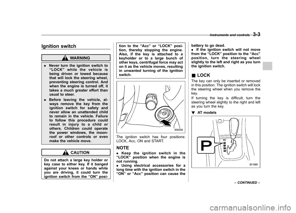
The ignition switch has four positions:
LOCK, Acc, ON and START. NOTE . Keep the ignition switch in the
“ LOCK ”position when the engine is
not running. . Using electrical accessories for a
long time with the ignition switch in the“ ON ”or “Acc ”position can cause the battery to go dead..
If the ignition switch will not move
from the “LOCK ”position to the “Acc ”
position, turn the steering wheel
slightly to the left and right as you turn
the ignition switch. & LOCK
The key can only be inserted or removed
in this position. The ignition switch will lock
the steering wheel when you remove the
key.
If turning the key is difficult, turn the
steering wheel slightly to the right and left
as you turn the key. ! AT models
Instruments and controls 3-3
– CONTINUED –
Page 139 of 458
3-20Instruments and controls
the telltale will flash for approximately one
minute and then remain continuously
illuminated. This sequence will continue
upon subsequent vehicle start-ups as long
as the malfunction exists. When the
malfunction indicator is illuminated, the
system may not be able to detect or signal
low tire pressure as intended. TPMS
malfunctions may occur for a variety of
reasons, including the installation of re-
placement or alternate tires or wheels on
the vehicle that prevent the TPMS from
functioning properly. Always check the
TPMS malfunction telltale after replacing
one or more tires or wheels on your
vehicle to ensure that the replacement or
alternate tires and wheels allow the TPMS
to continue to function properly.
Should the warning light illuminate stea-
dily after blinking for approximately one
minute, have the system inspected by
your nearest SUBARU dealer as soon aspossible.
WARNING
If this light does not illuminate
briefly after the ignition switch is
turned ON or the light illuminates
steadily after blinking for approxi-
mately one minute, you should have
your Tire Pressure Monitoring Sys-
tem checked at a SUBARU dealer as soon as possible.
If this light illuminates while driving,
never brake suddenly and keep
driving straight ahead while gradu-
ally reducing speed. Then slowly
pull off the road to a safe place.
Otherwise an accident involving
serious vehicle damage and serious
personal injury could occur.
If this light still illuminates while
driving after adjusting the tire pres-
sure, a tire may have significant
damage and a fast leak that causes
the tire to lose air rapidly. If you have
a flat tire, replace it with a spare tire
as soon as possible.
When a spare tire is mounted or a
wheel rim is replaced without the
original pressure sensor/transmitter
being transferred, the Low tire pres-
sure warning light will illuminate
steadily after blinking for approxi-
mately one minute. This indicates
the TPMS is unable to monitor all
four road wheels. Contact your
SUBARU dealer as soon as possible
for tire and sensor replacement and/
or system resetting.
If the light illuminates steadily after
blinking for approximately one min-
ute, promptly contact a SUBARU
dealer to have the system inspected.
CAUTION
The tire pressure monitoring system
is NOT a substitute for manually
checking tire pressure. The tire
pressure should be checked peri-
odically (at least monthly) using a
tire gauge. After any change to tire
pressure(s), the tire pressure mon-
itoring system will not re-check tire
inflation pressures until the vehicle
is first driven more than 20 mph (32
km/h). After adjusting the tire pres-
sures, increase the vehicle speed to
at least 20 mph (32 km/h) to start the
TPMS re-checking of the tire infla-
tion pressures. If the tire pressures
are now above the severe low
pressure threshold, the low tire
pressure warning light should turn
off a few minutes later. Therefore, be
sure to install the specified size for
the front and rear tires.
Page 141 of 458

3-22Instruments and controls
If the brake system warning light should
illuminate while driving (with the parking
brake fully released and with the ignition
switch positioned in “ON ”), it could be an
indication of leaking of brake fluid or worn
brake pads. If this occurs, immediately
stop the vehicle at the nearest safe place
and check the brake fluid level. If the fluid
level is below the “MIN ”mark in the
reservoir, do not drive the vehicle. Have
the vehicle towed to the nearest SUBARU
dealer for repair. ! Electronic Brake Force Distribution
(EBD) system warning
The brake system warning light also
illuminates if a malfunction occurs in the
EBD system. In that event, it illuminates
together with the ABS warning light.
The EBD system may be malfunctioning if
the brake system warning light and ABS
warning light illuminate simultaneously
during driving.
Even if the EBD system fails, the conven-
tional braking system will still function.
However, the rear wheels will be more
prone to locking when the brakes are
applied harder than usual and the vehi-cle ’s motion may therefore become some-
what harder to control.
If the brake system warning light and ABS
warning light illuminate simultaneously, take the following steps.
1. Stop the vehicle in the nearest safe,
flat place.
2. Shut down the engine, apply the
parking brake and then restart it.
3. Release the parking brake. If both
warning lights turn off, the EBD system
may be malfunctioning. Drive carefully to
the nearest SUBARU dealer and have the
system inspected.
4. If both warning lights illuminate again
and remain illuminated after the engine
has been restarted, shut down the engine
again, apply the parking brake, and check
the brake fluid level.
5. If the brake fluid level is not below the “
MIN ”mark, the EBD system may be
malfunctioning. Drive carefully to the
nearest SUBARU dealer and have the
system inspected.
6. If the brake fluid level is below the “ MIN ”mark, DO NOT drive the vehicle.
Instead, have the vehicle towed to the
nearest SUBARU dealer for repair.
& Low fuel warning light
The low fuel warning light illuminates
when the tank is nearly empty approxi-
mately 2.6 US gal (10.0 liters, or 2.2 Imp
gal). It only operates when the ignition
switch is in the “ON ”position. When this light illuminates, fill the fuel tank immedi-
ately.
NOTE
This light does not turn off unless the
tank is replenished up to an internal
fuel quantity of approximately 3.7 US
gal (14 liters, 3.1 Imp gal).
CAUTION
Promptly put fuel in the tank when-
ever the low fuel warning light
illuminates. Engine misfires as a
result of an empty tank could cause
damage to the engine.
& Hill start assist warning
light (MT models –if
equipped)/Hill start as-
sist OFF indicator light (STI)
! Hill start assist warning light
While the engine is rotating, if there are
any malfunctions in the Hill start assist
system, the light will illuminate.
WARNING
When the Hill start assist warning
Page 142 of 458
light illuminates, have the vehicle
inspected at an authorized SUBARU
dealer.
! Hill start assist OFF indicator light(STI)
While the Hill start assist system is
deactivated, the Hill start assist OFF
indicator light illuminates continuously to
inform the driver that the Hill start assist
system is not operational. & Door open warning light
The door open warning light illuminates if
any door or the rear gate is not fullyclosed.
Always make sure this light is not illumi-
nated before you start to drive. &All-Wheel Drive warn-
ing light (AT models)
This light illuminates when All-Wheel
Drive is disengaged and the drive me-
chanism is switched to Front Wheel Drive
for maintenance or similar purposes.
It flashes if the vehicle is driven with tires
of differing diameters fitted on the wheels
or with an excessively low air pressure in
any of the tires.
CAUTION
Continuing to drive with the AWD
warning light flashing can damage
the powertrain. If the AWD warning
light starts to flash, promptly park in
a safe place and check whether the
tires have differing diameters and
whether any of the tires has an
excessively low inflation pressure.
& Vehicle Dynamics
Control operation indi-
cator light
It blinks when the skid suppression func-
tion is activated. It illuminates only when
the traction control function is operating.
The Vehicle Dynamics Control system is
probably malfunctioning under any of the
following conditions. Have your vehicle
checked at a SUBARU dealer immedi-
ately. .The light does not illuminate when the
ignition switch is turned to the “ON ”
position.. The light does not turn off even after a
period of approximately 2 seconds after
the ignition switch has been turned to the“ ON ”position. &
Vehicle Dynamics
Control warning light/
Vehicle Dynamics Con-
trol OFF indicator light/
Traction Control OFF in-
dicator light (STI)
This warning light has both the function of
indicating malfunctions in the Vehicle
Dynamics Control system and the function
of indicating that the Vehicle Dynamics
Control system has been deactivated or
only the Traction Control system has beendeactivated.
It illuminates in the event of a malfunction
in the system and is on when the Vehicle
Dynamics Control system is not operating
or only the Traction Control system is notoperating. STI:
This warning light illuminates in yellow for
approximately 1 second when the ignition
switch is turned to the “ON ”position. After
that, this warning light changes to green
and remains illuminated in green for 1
second, and then turns off. It indicates that
the Vehicle Dynamics Control system is
operating normally. Instruments and controls
3-23
– CONTINUED –
Page 169 of 458
3-50Instruments and controls
CAUTION
. To prevent the battery from being
discharged, do not operate the
defogger and deicer system con-
tinuously for any longer than
necessary.
. Do not use sharp instruments or
window cleaner containing abra-
sives to clean the inner surface
of the rear window. They may
damage the conductors printed
on the window.
NOTE . Turn on the defogger and deicer
system if the wipers are frozen to the windshield.. If the windshield is covered with
snow, remove the snow so that the
windshield wiper deicer works effec-
tively.. While the defogger and deicer sys-
tem is in the continuous operation
mode, if the vehicle speed remains at
9 mph (15 km/h) or less for 15 minutes,
the windshield wiper deicer automati-
cally stops operating, though the rear
window defogger and outside mirror
defogger maintain continuous opera-
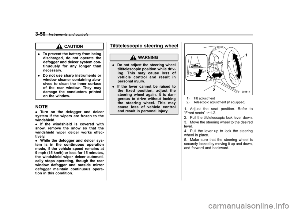
tion in this condition. Tilt/telescopic steering wheel
WARNING
. Do not adjust the steering wheel
tilt/telescopic position while driv-
ing. This may cause loss of
vehicle control and result in
personal injury.
. If the lever cannot be raised to
the fixed position, adjust the
steering wheel again. It is dan-
gerous to drive without locking
the steering wheel. This may
cause loss of vehicle control
and result in personal injury.
1) Tilt adjustment
2) Telescopic adjustment (if equipped)
1. Adjust the seat position. Refer to “ Front seats ”F 1-2.
2. Pull the tilt/telescopic lock lever down.
3. Move the steering wheel to the desired level.
4. Pull the lever up to lock the steering
wheel in place.
5. Make sure that the steering wheel is
securely locked by moving it up and down,
and forward and backward.
Page 174 of 458

&Center and side ventilators
! Center ventilators
Move the tab to adjust the flow direction. !
Side ventilators
1) Open
2) Close
3) Thumb-wheel
Move the tab to adjust the flow direction.
To open or close the ventilator, turn the
thumb-wheel up or down. Manual climate control sys-
tem (if equipped) &
Control panel
1) Temperature control dial
2) Fan speed control dial
3) Airflow control dial
4) Control switch of the defogger and deicer
system (Refer to “Defogger and deicer ”
F 3-48.)
5) Air conditioner button
6) Air inlet selection button
! Temperature control dial
This dial regulates the temperature of
airflow from the air outlets over a range
fromtheblueside(cool)toredside(warm). Climate control
4-3
– CONTINUED –