2011 SUBARU IMPREZA WRX oil
[x] Cancel search: oilPage 172 of 458
Ventilator.............................................................. 4-2
Airflow selection ................................................. 4-2
Center and side ventilators .................................. 4-3
Manual climate control system (if equipped) ..................................................... 4-3
Control panel ...................................................... 4-3
Heater operation ................................................. 4-5
Air conditioner operation ..................................... 4-7
Automatic climate control system (if equipped) ..................................................... 4-8
Control panel ...................................................... 4-8
To use as full-automatic climate control system .............................................................. 4-8
To use as semi-automatic climate control system .............................................................. 4-8
Fan speed control dial ......................................... 4-9
Temperature control dial ...................................... 4-9
Airflow control dial .............................................. 4-9
Air inlet selection button .................................... 4-10 Air conditioner button
........................................ 4-11
Temperature sensors ......................................... 4-11
Operating tips for heater and air conditioner ...................................................... 4-12
Cleaning ventilation grille ................................... 4-12
Efficient cooling after parking in direct sunlight ........................................................... 4-12
Lubrication oil circulation in the refrigerant circuit .............................................................. 4-12
Checking air conditioning system before summer season ............................................................ 4-12
Cooling and dehumidifying in high humidity and low temperature weather conditions ................. 4-12
Air conditioner compressor shut-off when engine is heavily loaded .............................................. 4-13
Refrigerant for your climate control system ... ..... 4-13
Air filtration system ........................................... 4-13
Replacing an air filter ......................................... 4-13Climate control
4
Page 183 of 458
4-12Climate control
properly and become damaged, the sys-
tem may not be able to control the interior
temperature correctly. To avoid damaging
the sensors, observe the following pre-cautions. –Do not subject the sensors to impact.
– Keep water away from the sensors.
– Do not cover the sensors.
The sensors are located as follows.– Solar sensor: beside the windshield
defroster grille.– Interior air temperature sensor: near
the ignition switch.– Outside temperature sensor: behind
the front grille. Operating tips for heater and
air conditioner &
Cleaning ventilation grille
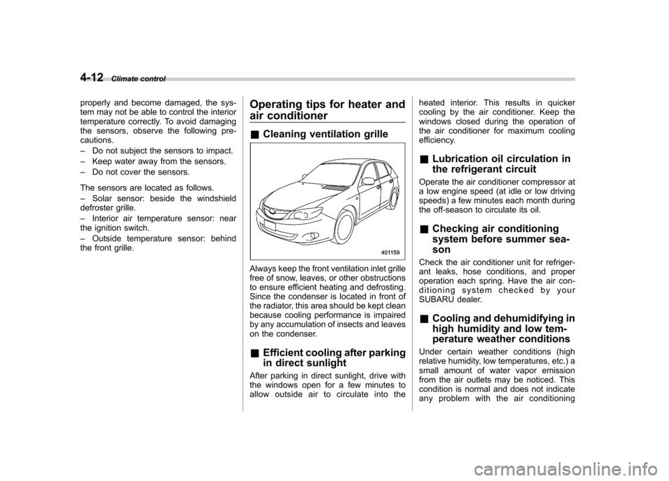
Always keep the front ventilation inlet grille
free of snow, leaves, or other obstructions
to ensure efficient heating and defrosting.
Since the condenser is located in front of
the radiator, this area should be kept clean
because cooling performance is impaired
by any accumulation of insects and leaves
on the condenser. &Efficient cooling after parking
in direct sunlight
After parking in direct sunlight, drive with
the windows open for a few minutes to
allow outside air to circulate into the heated interior. This results in quicker
cooling by the air conditioner. Keep the
windows closed during the operation of
the air conditioner for maximum cooling
efficiency. &
Lubrication oil circulation in
the refrigerant circuit
Operate the air conditioner compressor at
a low engine speed (at idle or low driving
speeds) a few minutes each month during
the off-season to circulate its oil. & Checking air conditioning
system before summer sea-son
Check the air conditioner unit for refriger-
ant leaks, hose conditions, and proper
operation each spring. Have the air con-
ditioning system checked by your
SUBARU dealer. & Cooling and dehumidifying in
high humidity and low tem-
perature weather conditions
Under certain weather conditions (high
relative humidity, low temperatures, etc.) a
small amount of water vapor emission
from the air outlets may be noticed. This
condition is normal and does not indicate
any problem with the air conditioning
Page 245 of 458
5-58Audio
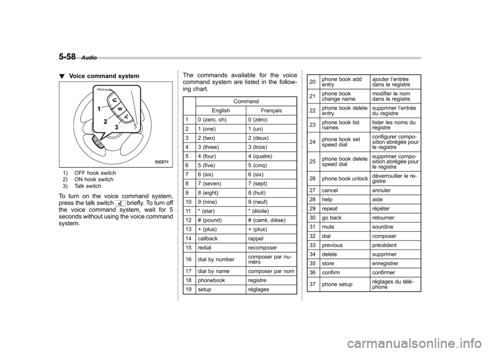
!Voice command system
1) OFF hook switch
2) ON hook switch
3) Talk switch
To turn on the voice command system,
press the talk switch
briefly. To turn off
the voice command system, wait for 5
seconds without using the voice commandsystem. The commands available for the voice
command system are listed in the follow-
ing chart.
Command
English Français
1 0 (zero, oh) 0 (zéro)
2 1 (one) 1 (un)
3 2 (two) 2 (deux)
4 3 (three) 3 (trois)
5 4 (four) 4 (quatre)
6 5 (five) 5 (cinq)
7 6 (six) 6 (six)
8 7 (seven) 7 (sept)
9 8 (eight) 8 (huit)
10 9 (nine) 9 (neuf)
11 * (star) * (étoile)
12 # (pound) # (carré, dièse)
13 + (plus) + (plus)
14 callback rappel
15 redial recomposer
16 dial by number composer par nu- méro
17 dial by name composer par nom
18 phonebook registre
19 setup réglages 20
phone book add entry ajouter l
’entrée
dans le registre
21 phone book
change name modifier le nom
dans le registre
22 phone book deleteentry supprimer l
’entrée
du registre
23 phone book listnames lister les noms duregistre
24 phone book set
speed dial configurer compo-
sition abrégée pour
le registre
25 phone book delete
speed dial supprimer compo-
sition abrégée pour
le registre
26 phone book unlock déverrouiller le re-gistre
27 cancel annuler
28 help aide
29 repeat répéter
30 go back retourner
31 mute sourdine
32 dial composer
33 previous précédent
34 delete supprimer
35 store enregistrer
36 confirm confirmer
37 phone setup réglages du télé- phone
Page 257 of 458
6-8Interior equipment
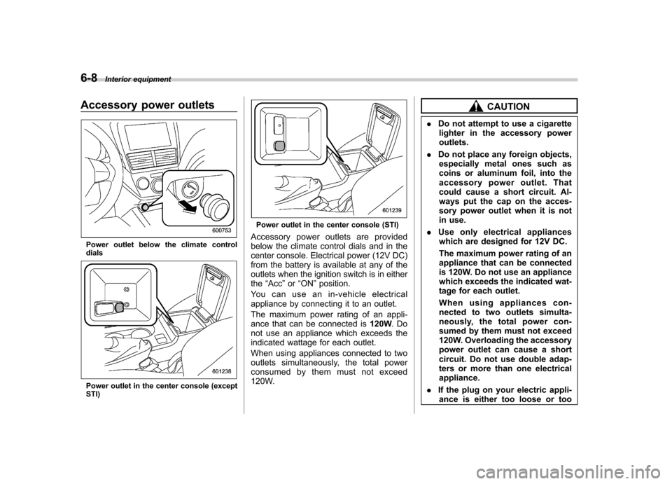
Accessory power outlets
Power outlet below the climate control dials
Power outlet in the center console (except STI)
Power outlet in the center console (STI)
Accessory power outlets are provided
below the climate control dials and in the
center console. Electrical power (12V DC)
from the battery is available at any of the
outlets when the ignition switch is in eitherthe “Acc ”or “ON ”position.
You can use an in-vehicle electrical
appliance by connecting it to an outlet.
The maximum power rating of an appli-
ance that can be connected is 120W.Do
not use an appliance which exceeds the
indicated wattage for each outlet.
When using appliances connected to two
outlets simultaneously, the total power
consumed by them must not exceed
120W.
CAUTION
. Do not attempt to use a cigarette
lighter in the accessory power outlets.
. Do not place any foreign objects,
especially metal ones such as
coins or aluminum foil, into the
accessory power outlet. That
could cause a short circuit. Al-
ways put the cap on the acces-
sory power outlet when it is not
in use.
. Use only electrical appliances
which are designed for 12V DC.
The maximum power rating of an
appliance that can be connected
is 120W. Do not use an appliance
which exceeds the indicated wat-
tage for each outlet.
When using appliances con-
nected to two outlets simulta-
neously, the total power con-
sumed by them must not exceed
120W. Overloading the accessory
power outlet can cause a short
circuit. Do not use double adap-
ters or more than one electricalappliance.
. If the plug on your electric appli-
ance is either too loose or too
Page 271 of 458
7-8Starting and operating
CAUTION
Resultant vehicle damage due to
improper testing is not covered
under the SUBARU Limited War-
ranty and is the responsibility of
the state inspection program or its
contractors or licensees.
The EPA has issued regulations for
inspecting the On-Board Diagnostic
(OBD) system as part of the state emis-
sions inspection. The OBD system is
designed to detect engine and transmis-
sion problems that might cause vehicle
emissions to exceed allowable limits.
These inspections apply to all 1996 model
year and newer passenger cars and light
trucks. Over 30 states plus the District of
Columbia have implemented the OBD
system inspection. . The inspection of the OBD system
consists of a visual operational check of the “CHECK ENGINE ”warning light/mal-
function indicator lamp (MIL) and an
examination of the OBD system with an
electronic scan tool while the engine isrunning. . Avehicle
passes the OBD system
inspection if proper illumination of the “ CHECK ENGINE ”warning light/MIL is
observed, there are nostored diagnostic trouble codes, and the OBD system
readiness monitors are complete. .
A vehicle
fails the OBD inspection if the
“ CHECK ENGINE ”warning light/MIL is
not properly operating or there are one or
more diagnostic trouble codes stored in
the vehicle ’s computer with the “CHECK
ENGINE ”warning light/MIL illuminated.
. A state emission inspection may reject
(not pass or fail) a vehicle if the number of
OBD system readiness monitors “Not
Ready ”is greater than one. Under this
condition, the vehicle operator should be
instructed to drive his/her vehicle for a few
days to set the monitors and return for an
emission re-inspection. . Owners of rejected or failing vehicles
should contact their SUBARU Dealer for service. Preparing to drive
You should perform the following checks
and adjustments every day before you
start driving.
1. Check that all windows, mirrors, and
lights are clean and unobstructed.
2. Check the appearance and condition
of the tires. Also check tires for properinflation.
3. Look under the vehicle for any sign of leaks.
4. Check that the hood, trunk (4-door)
and rear gate (5-door) are fully closed.
5. Check the adjustment of the seat.
6. Check the adjustment of the inside
and outside mirrors.
7. Fasten your seatbelt. Check that your
passengers have fastened their seatbelts.
8. Check the operation of the warning
and indicator lights when the ignition
switch is turned to the
“ON ”position.
9. Check the gauges, indicator and warn-
ing lights after starting the engine.
NOTE
Engine oil, engine coolant, brake fluid,
washer fluid and other fluid levels
should be checked daily, weekly or at
fuel stops.
Page 276 of 458

not. Remote engine start transmitter pro-
gramming and feature programming can
be adjusted using the following procedure.
1. Open the driver’s door (the driver ’s
door must remain opened throughout the
entire process).
2. Insert the key into the vehicle ’s ignition
switch and turn to the “ON ”position.
3. Locate the small black programming
button behind the fuse box cover, on the
driver ’s side left under the dashboard
panel.
4. Press and hold the black programming
button for 10 to 15 seconds. The horn will
honk and the turn signal lights will flash
three times to indicate that the system has
entered programming mode. At this point
you can proceed to either step 5 or step 6.
5. To program a remote engine start
transmitter: press and release the “
”
button on each transmitter. The horn will
honk and the turn signal lights will flash
one time to indicate a successful trans-
mitter learn each time the “
”button is
pressed. You can program up to eight transmitters.
6. To toggle the Horn Confirmation chirps
ON/OFF: depress and release the brake
pedal to toggle the feature. The horn will
chirp and the turn signal lights will flash
one time to indicate Confirmation Horn
Chirps are “OFF ”. The horn will honk and the turn signal lights will flash 2 times to
indicate Confirmation Horn Chirps are“
ON ”. Depressing the brake pedal repeat-
edly will toggle the feature ON or OFF
each time.
7. To exit the remote engine start trans-
mitter and feature programming mode,
turn the ignition switch to the “LOCK ”
position, remove the key from the ignition
switch and test operation of the remote
engine start transmitter(s) and horn con-
firmation feature.
& System maintenance
! Changing the batteries
CAUTION
. Do not let dust, oil or water get on
or in the remote engine start
transmitter when replacing the
battery.
. Be careful not to damage the
printed circuit board in the re-
mote engine start transmitter
when replacing the battery.
. Be careful not to allow children to
touch the battery and any re-
moved parts; children could
swallow them.
. There is a danger of explosion if an incorrect replacement battery
is used. Replace only with the
same or equivalent type of bat-
tery.
. Batteries should not be exposed
to excessive heat such as sun-
shine, fire or the like.
The two 3-volt lithium batteries (modelCR-1220 ) supplied in your remote engine
start transmitter should last approximately
3 years, depending on usage. When the
batteries begin to weaken, you will notice
a decrease in range (distance from the
vehicle that your remote engine start
system operates). Follow the instructions
below to change the remote engine start
transmitter batteries.
Starting and operating 7-13
– CONTINUED –
Page 289 of 458
7-26Starting and operating
& Selection of manual mode
NOTE
Please read the following points care-
fully and bear them in mind when using
the manual mode. . If you attempt to shift down when
the engine speed is too high, i.e., when
a downshift would push the tachometer
needle beyond the red zone, beeps will
be emitted to warn you that the down-
shift is not possible.. If you attempt to shift up when the
vehicle speed is too low, the transmis-
sion will not respond.. You can perform a skip-shift (for
example, from 4th to 2nd) by operating
the select lever twice in rapid succes-sion.. The transmission automatically se-
lects 1st gear when the vehicle stopsmoving.. If the temperature of the automatic
transmission fluid becomes too high,the “AT OIL TEMP ”warning light will
illuminate and upshifts to 4th gear will
not be possible. Immediately stop the
vehicle in a safe place and let the
engine idle until the warning light turnsoff.
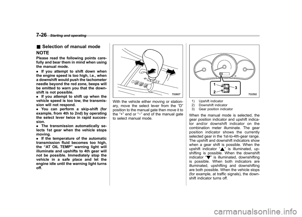
With the vehicle either moving or station-
ary, move the select lever from the “D ”
position to the manual gate then move it tothe “+ ” end or “� ” end of the manual gate
to select manual mode.1) Upshift indicator
2) Downshift indicator
3) Gear position indicator
When the manual mode is selected, the
gear position indicator and upshift indica-
tor and/or downshift indicator on the
combination meter illuminate. The gear
position indicator shows the currently
selected gear in the 1st-to-4th-gear range.
The upshift and downshift indicators show
when a gear shift is possible. When the
upshift indicator “
”is illuminated, up-
shifting is possible. When the downshift indicator “
”is illuminated, downshifting
is possible. When both indicators are
illuminated, upshifting and downshifting
are both possible. When the vehicle stops
(for example, at traffic signals), the down-
shift indicator turns off.
Page 304 of 458
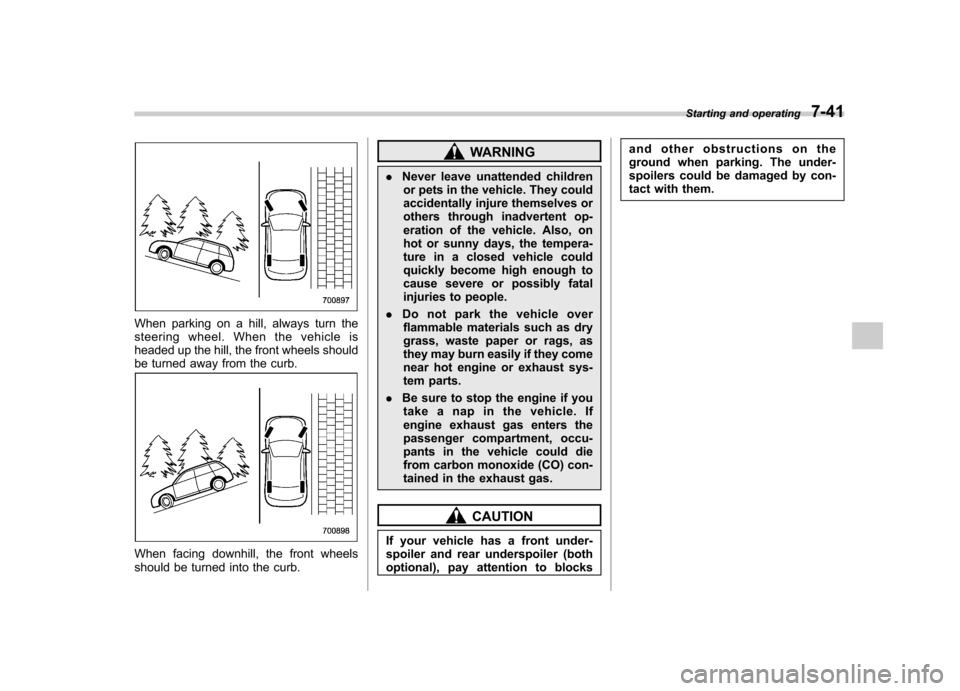
When parking on a hill, always turn the
steering wheel. When the vehicle is
headed up the hill, the front wheels should
be turned away from the curb.
When facing downhill, the front wheels
should be turned into the curb.
WARNING
. Never leave unattended children
or pets in the vehicle. They could
accidentally injure themselves or
others through inadvertent op-
eration of the vehicle. Also, on
hot or sunny days, the tempera-
ture in a closed vehicle could
quickly become high enough to
cause severe or possibly fatal
injuries to people.
. Do not park the vehicle over
flammable materials such as dry
grass, waste paper or rags, as
they may burn easily if they come
near hot engine or exhaust sys-
tem parts.
. Be sure to stop the engine if you
take a nap in the vehicle. If
engine exhaust gas enters the
passenger compartment, occu-
pants in the vehicle could die
from carbon monoxide (CO) con-
tained in the exhaust gas.
CAUTION
If your vehicle has a front under-
spoiler and rear underspoiler (both
optional), pay attention to blocks and other obstructions on the
ground when parking. The under-
spoilers could be damaged by con-
tact with them.
Starting and operating
7-41