2011 SUBARU IMPREZA WRX mirror
[x] Cancel search: mirrorPage 162 of 458
!Compass calibration
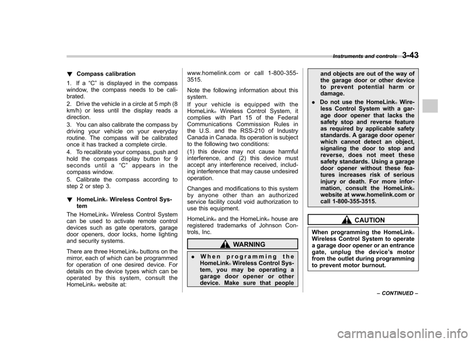
1. If a “C ” is displayed in the compass
window, the compass needs to be cali- brated.
2. Drive the vehicle in a circle at 5 mph (8
km/h) or less until the display reads a direction.
3. You can also calibrate the compass by
driving your vehicle on your everyday
routine. The compass will be calibrated
once it has tracked a complete circle.
4. To recalibrate your compass, push and
hold the compass display button for 9
seconds until a “C ” appears in the
compass window.
5. Calibrate the compass according to
step 2 or step 3. ! HomeLink
®Wireless Control Sys-
tem
The HomeLink
®Wireless Control System
can be used to activate remote control
devices such as gate operators, garage
door openers, door locks, home lighting
and security systems.
There are three HomeLink
®buttons on the
mirror, each of which can be programmed
for operation of one desired device. For
details on the device types which can be
operated by this system, consult the HomeLink
®website at: www.homelink.com or call 1-800-355-3515.
Note the following information about this system.
Ifyourvehicleisequippedwiththe HomeLink
®Wireless Control System, it
complies with Part 15 of the Federal
Communications Commission Rules in
the U.S. and the RSS-210 of Industry
Canada in Canada. Its operation is subject
to the following two conditions:
(1) this device may not cause harmful
interference, and (2) this device must
accept any interference received, includ-
ing interference that may cause undesiredoperation.
Changes and modifications to this system
by anyone other than an authorized
service facility could void authorization to
use this equipment. HomeLink
®and the HomeLink®house are
registered trademarks of Johnson Con-
trols, Inc.
WARNING
. When programming the
HomeLink
®Wireless Control Sys-
tem, you may be operating a
garage door opener or other
device. Make sure that people and objects are out of the way of
the garage door or other device
to prevent potential harm ordamage.
. Do not use the HomeLink
®Wire-
less Control System with a gar-
age door opener that lacks the
safety stop and reverse feature
as required by applicable safety
standards. A garage door opener
which cannot detect an object,
signaling the door to stop and
reverse, does not meet these
safety standards. Using a garage
door opener without these fea-
tures increases risk of serious
injury or death. For more infor-
mation, consult the HomeLink
®website at www.homelink.com or
call 1-800-355-3515.
CAUTION
When programming the HomeLink
®Wireless Control System to operate
a garage door opener or an entrance
gate, unplug the device ’s motor
from the outlet during programming
to prevent motor burnout. Instruments and controls
3-43
– CONTINUED –
Page 166 of 458
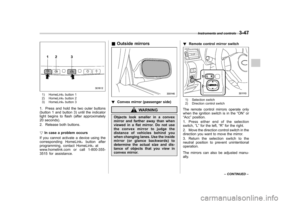
1) HomeLink®button 1
2) HomeLink®button 2
3) HomeLink®button 3
1. Press and hold the two outer buttons
(button 1 and button 3) until the indicator
light begins to flash (after approximately
20 seconds).
2. Release both buttons. ! In case a problem occurs
If you cannot activate a device using the
corresponding HomeLink
®button after
programming, contact HomeLink®at
www.homelink.com or call 1-800-355-
3515 for assistance. &
Outside mirrors
! Convex mirror (passenger side)
WARNING
Objects look smaller in a convex
mirror and farther away than when
viewed in a flat mirror. Do not use
the convex mirror to judge the
distance of vehicles behind you
when changing lanes. Use the inside
mirror (or glance backwards) to
determine the actual size and dis-
tance of objects that you view in
convex mirror. !
Remote control mirror switch
1) Selection switch
2) Direction control switch
The remote control mirrors operate only
when the ignition switch is in the “ON ”or
“ Acc ”position.
1. Press either end of the selectionswitch, “L ” for the left, “R ”for the right.
2. Move the direction control switch in the
direction you want to move the mirror.
3. Return the selection switch to the
neutral position to prevent unintentionaloperation.
The mirrors can also be adjusted manu-
ally. Instruments and controls
3-47
– CONTINUED –
Page 167 of 458
3-48Instruments and controls
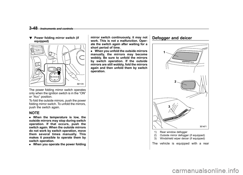
!Power folding mirror switch (if equipped)
The power folding mirror switch operates
only when the ignition switch is in the “ON ”
or “Acc ”position.
To fold the outside mirrors, push the power
folding mirror switch. To unfold the mirrors,
push the switch again. NOTE . When the temperature is low, the
outside mirrors may stop during switch
operation. If that occurs, push the
switch again. When the outside mirrors
do not work by switch operation, move
them several times manually. This
makes it possible to operate them by
switch operation.. When you operate the power folding mirror switch continuously, it may not
work. This is not a malfunction. Oper-
ate the switch again after waiting for a
short period of time..
When you unfold the outside mirrors
manually, the mirrors may become
wobbly. Be sure to unfold the mirrors
by switch operation. If the outside
mirrors are still wobbly, fold the mirrors
again and then unfold them by switchoperation. Defogger and deicer
1) Rear window defogger
2) Outside mirror defogger (if equipped)
3) Windshield wiper deicer (if equipped)
The vehicle is equipped with a rear
Page 168 of 458

window defogger. Some models are also
equipped with an outside mirror defogger
and/or windshield wiper deicer. The de-
fogger and deicer system is activated only
when the ignition switch is in the“ON ”
position.
Manual climate control system
Automatic climate control system
To activate the defogger and deicer
system, push the control switch that is
located on the climate control panel. The
rear window defogger, outside mirror
defogger and windshield wiper deicer are
activated simultaneously. The indicator
light on the control switch illuminates while
the defogger and deicer system is acti-vated.
To turn them off, push the control switch
again. They also turn off when the ignition
switch is turned to the “Acc ”or “LOCK ”
position.
The defogger and deicer system will
automatically shut off after approximately
15 minutes. If the rear window and the
outside mirrors have been cleared and the windshield wiper blades have been deiced
completely before that time, push the
control switch to turn them off. If defrost-
ing, defogging or deicing is not complete,
you have to push the control switch to turn
them on again.
For models with the automatic climate
control system,
it is possible to set the
defogger and deicer system for the con-
tinuous operation mode as follows. . Models with genuine SUBARU navi-
gation system:
The setting can be changed for the
continuous operation mode using the
navigation monitor. For details, refer to
the Owner ’s Manual supplement for the
navigation system.
The setting can also be changed by a
SUBARU dealer. Contact your SUBARU
dealer for details. . Models without genuine SUBARU
navigation system:
The setting can be changed by a
SUBARU dealer. Contact your SUBARU
dealer for details.
If the battery voltage drops below the
permissible level, continuous operation of
the defogger and deicer system is can-
celed and the system stops operating. Instruments and controls
3-49
– CONTINUED –
Page 169 of 458
3-50Instruments and controls
CAUTION
. To prevent the battery from being
discharged, do not operate the
defogger and deicer system con-
tinuously for any longer than
necessary.
. Do not use sharp instruments or
window cleaner containing abra-
sives to clean the inner surface
of the rear window. They may
damage the conductors printed
on the window.
NOTE . Turn on the defogger and deicer
system if the wipers are frozen to the windshield.. If the windshield is covered with
snow, remove the snow so that the
windshield wiper deicer works effec-
tively.. While the defogger and deicer sys-
tem is in the continuous operation
mode, if the vehicle speed remains at
9 mph (15 km/h) or less for 15 minutes,
the windshield wiper deicer automati-
cally stops operating, though the rear
window defogger and outside mirror
defogger maintain continuous opera-
tion in this condition. Tilt/telescopic steering wheel
WARNING
. Do not adjust the steering wheel
tilt/telescopic position while driv-
ing. This may cause loss of
vehicle control and result in
personal injury.
. If the lever cannot be raised to
the fixed position, adjust the
steering wheel again. It is dan-
gerous to drive without locking
the steering wheel. This may
cause loss of vehicle control
and result in personal injury.
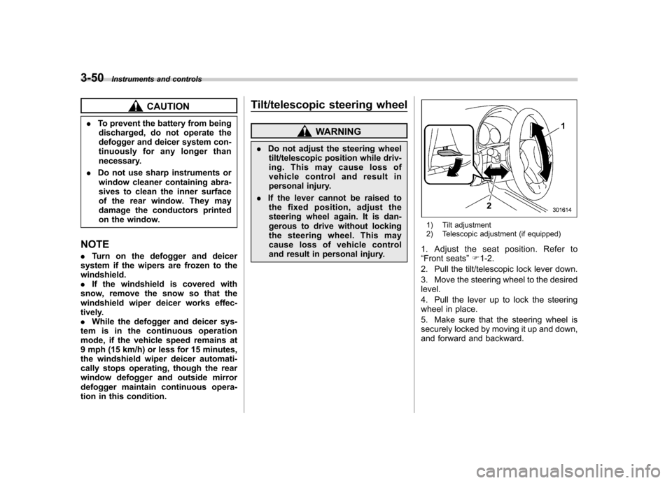
1) Tilt adjustment
2) Telescopic adjustment (if equipped)
1. Adjust the seat position. Refer to “ Front seats ”F 1-2.
2. Pull the tilt/telescopic lock lever down.
3. Move the steering wheel to the desired level.
4. Pull the lever up to lock the steering
wheel in place.
5. Make sure that the steering wheel is
securely locked by moving it up and down,
and forward and backward.
Page 250 of 458
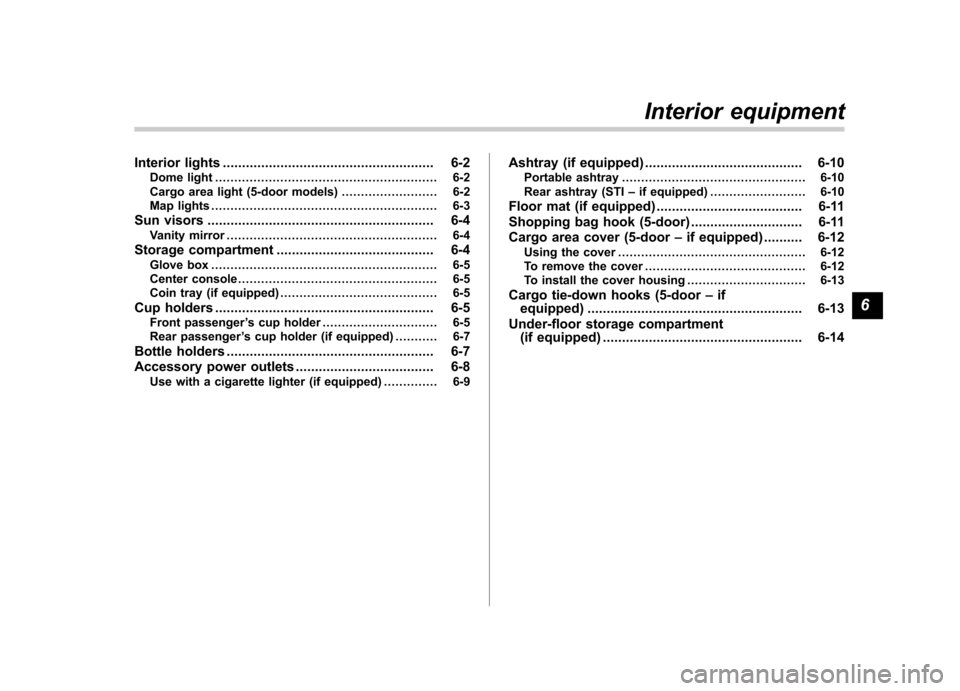
Interior lights....................................................... 6-2
Dome light .......................................................... 6-2
Cargo area light (5-door models) ......................... 6-2
Map lights ........................................................... 6-3
Sun visors ........................................................... 6-4
Vanity mirror ....................................................... 6-4
Storage compartment ......................................... 6-4
Glove box ........................................................... 6-5
Center console .................................................... 6-5
Coin tray (if equipped) ......................................... 6-5
Cup holders ......................................................... 6-5
Front passenger ’s cup holder .............................. 6-5
Rear passenger ’s cup holder (if equipped) ........... 6-7
Bottle holders ...................................................... 6-7
Accessory power outlets .................................... 6-8
Use with a cigarette lighter (if equipped) .. ............ 6-9Ashtray (if equipped)
......................................... 6-10
Portable ashtray ................................................ 6-10
Rear ashtray (STI –if equipped) ......................... 6-10
Floor mat (if equipped) ...................................... 6-11
Shopping bag hook (5-door) ............................. 6-11
Cargo area cover (5-door –if equipped) .......... 6-12
Using the cover ................................................. 6-12
To remove the cover .......................................... 6-12
To install the cover housing ............................... 6-13
Cargo tie-down hooks (5-door –if
equipped) ........................................................ 6-13
Under-floor storage compartment (if equipped) .................................................... 6-14Interior equipment
6
Page 253 of 458

6-4Interior equipment
Sun visors
To block out glare, swing down the visors.
To use the sun visor at a side window,
swing it down and move it sideways. &
Vanity mirror
CAUTION
Keep the vanity mirror cover closed
while the car is being driven to avoid
being temporarily blinded by the
glare of bright light.
To use the vanity mirror, swing down the
sun visor and open the vanity mirror cover. Storage compartment
CAUTION
. Always keep the storage com-
partment closed while driving to
reduce the risk of injury in the
event of a sudden stop or anaccident.
. Do not store spray cans, contain-
ers with flammable or corrosive
liquids or any other dangerous
items in the storage compart-ment.
Page 271 of 458

7-8Starting and operating
CAUTION
Resultant vehicle damage due to
improper testing is not covered
under the SUBARU Limited War-
ranty and is the responsibility of
the state inspection program or its
contractors or licensees.
The EPA has issued regulations for
inspecting the On-Board Diagnostic
(OBD) system as part of the state emis-
sions inspection. The OBD system is
designed to detect engine and transmis-
sion problems that might cause vehicle
emissions to exceed allowable limits.
These inspections apply to all 1996 model
year and newer passenger cars and light
trucks. Over 30 states plus the District of
Columbia have implemented the OBD
system inspection. . The inspection of the OBD system
consists of a visual operational check of the “CHECK ENGINE ”warning light/mal-
function indicator lamp (MIL) and an
examination of the OBD system with an
electronic scan tool while the engine isrunning. . Avehicle
passes the OBD system
inspection if proper illumination of the “ CHECK ENGINE ”warning light/MIL is
observed, there are nostored diagnostic trouble codes, and the OBD system
readiness monitors are complete. .
A vehicle
fails the OBD inspection if the
“ CHECK ENGINE ”warning light/MIL is
not properly operating or there are one or
more diagnostic trouble codes stored in
the vehicle ’s computer with the “CHECK
ENGINE ”warning light/MIL illuminated.
. A state emission inspection may reject
(not pass or fail) a vehicle if the number of
OBD system readiness monitors “Not
Ready ”is greater than one. Under this
condition, the vehicle operator should be
instructed to drive his/her vehicle for a few
days to set the monitors and return for an
emission re-inspection. . Owners of rejected or failing vehicles
should contact their SUBARU Dealer for service. Preparing to drive
You should perform the following checks
and adjustments every day before you
start driving.
1. Check that all windows, mirrors, and
lights are clean and unobstructed.
2. Check the appearance and condition
of the tires. Also check tires for properinflation.
3. Look under the vehicle for any sign of leaks.
4. Check that the hood, trunk (4-door)
and rear gate (5-door) are fully closed.
5. Check the adjustment of the seat.
6. Check the adjustment of the inside
and outside mirrors.
7. Fasten your seatbelt. Check that your
passengers have fastened their seatbelts.
8. Check the operation of the warning
and indicator lights when the ignition
switch is turned to the
“ON ”position.
9. Check the gauges, indicator and warn-
ing lights after starting the engine.
NOTE
Engine oil, engine coolant, brake fluid,
washer fluid and other fluid levels
should be checked daily, weekly or at
fuel stops.