2011 SUBARU IMPREZA WRX heating
[x] Cancel search: heatingPage 180 of 458

&Fan speed control dial
The fan operates only with the ignition
switch in the ON position. The fan speed
control dial is used to select the AUTO
(automatic control) mode or to select the
desired fan speed. The dial ’s positions
and their functions are as follows. OFF: The fan does not operate.
AUTO: The fan speed is adjusted auto-
maticallyinaccordancewiththeair
temperature inside and outside the pas-
senger compartment, the intensity of sun-
light, and other factors. SUBARU recom-
mends using the AUTO position.
Other positions: The fan speed can be
adjusted in 7 steps. NOTE
With the fan speed control dial in the
AUTO position and the airflow control
dial in the
“
”, “”,or “”position,
the fan does not operate during engine
warm-up until the engine coolant tem-
perature exceeds approximately 122 8F
(50 8C).
& Temperature control dial
This dial is used to set the desired interior
temperature. With the dial set to your
desired temperature, the system automa-
tically adjusts the temperature of air
supplied from the outlets such that the
desired temperature is achieved andmaintained.
If the dial is turned fully counterclockwise, the system gives maximum cooling per-
formance. If the dial is turned fully clock-
wise, the system gives maximum heatingperformance. &
Airflow control dial
Each dial position activates the following
air outlets. AUTO: The airflow control is adjusted
automatically in accordance with the air
temperature inside and outside the pas-
senger compartment, the intensity of sun-
light, and other factors. SUBARU recom-
mends using the AUTO position.
(Ventilation): Instrument panel outlets
(Bi-level): Instrument panel outlets and
foot outlets
(Heat): Foot outlets, both side outlets of Climate control
4-9
– CONTINUED –
Page 183 of 458
4-12Climate control
properly and become damaged, the sys-
tem may not be able to control the interior
temperature correctly. To avoid damaging
the sensors, observe the following pre-cautions. –Do not subject the sensors to impact.
– Keep water away from the sensors.
– Do not cover the sensors.
The sensors are located as follows.– Solar sensor: beside the windshield
defroster grille.– Interior air temperature sensor: near
the ignition switch.– Outside temperature sensor: behind
the front grille. Operating tips for heater and
air conditioner &
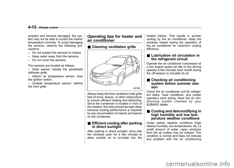
Cleaning ventilation grille
Always keep the front ventilation inlet grille
free of snow, leaves, or other obstructions
to ensure efficient heating and defrosting.
Since the condenser is located in front of
the radiator, this area should be kept clean
because cooling performance is impaired
by any accumulation of insects and leaves
on the condenser. &Efficient cooling after parking
in direct sunlight
After parking in direct sunlight, drive with
the windows open for a few minutes to
allow outside air to circulate into the heated interior. This results in quicker
cooling by the air conditioner. Keep the
windows closed during the operation of
the air conditioner for maximum cooling
efficiency. &
Lubrication oil circulation in
the refrigerant circuit
Operate the air conditioner compressor at
a low engine speed (at idle or low driving
speeds) a few minutes each month during
the off-season to circulate its oil. & Checking air conditioning
system before summer sea-son
Check the air conditioner unit for refriger-
ant leaks, hose conditions, and proper
operation each spring. Have the air con-
ditioning system checked by your
SUBARU dealer. & Cooling and dehumidifying in
high humidity and low tem-
perature weather conditions
Under certain weather conditions (high
relative humidity, low temperatures, etc.) a
small amount of water vapor emission
from the air outlets may be noticed. This
condition is normal and does not indicate
any problem with the air conditioning
Page 184 of 458
system. &Air conditioner compressor
shut-off when engine is
heavily loaded
To improve acceleration and gas mileage,
the air conditioner compressor is designed
to temporarily shut off during air condi-
tioner operation whenever the accelerator
is fully depressed such as during rapid
acceleration or when driving on a steepupgrade. & Refrigerant for your climate
control system
Your air conditioner uses ozone friendly
refrigerant HFC134a. Therefore, the meth-
od of adding, changing or checking the
refrigerant is different from the method for
CFC12 (freon). Consult your SUBARU
dealer for service. Repairs needed as a
result of using the wrong refrigerant are
not covered under warranty. Air filtration system
Replace the filter element according to the
replacement schedule as follows. This
schedule should be followed to maintain
the filter
’s dust collection ability. Under
extremely dusty conditions, the filter
should be replaced more frequently. It is
recommended that you have your filter
checked or replaced by your SUBARU
dealer. For replacement, use only a
genuine SUBARU air filter kit.
Replacement schedule: Every 12 months or 7,500 miles (12,000
km) whichever comes first
CAUTION
Contact your SUBARU dealer if the
following occurs, even if it is not yet
time to change the filter: . Reduction of the airflow through
the vents.
. Windshield gets easily fogged or
misted.
NOTE
The filter can influence the air condi-
tioning, heating and defroster perfor- mance if not properly maintained. &
Replacing an air filter
1. Remove the glove box. (1) Open the glove box.(2) Remove the damper shaft from the
glove box. Climate control
4-13
– CONTINUED –
Page 258 of 458
tight for the accessory power
outlet, this can result in a poor
contact or cause the plug to get
stuck. Only use plugs that fit
properly.
. Use of an electric appliance in the
accessory power outlet for a long
period of time while the engine is
not running can cause batterydischarge.
. Before driving your vehicle, make
sure that the plug and the cord
on your electrical appliance will
not interfere with your shifting
gears and operating the accel-
erator and brake pedals. If they
do, do not use the electrical
appliance while driving. &
Use with a cigarette lighter (if equipped)
To use the accessory power outlet below
the climate control as a cigarette lighter
socket, purchase the cigarette lighter plug,
which is an optional accessory. A cigarette
lighter plug is available from your
SUBARU dealer.
The cigarette lighter operates only when
the ignition switch is in the “ON ”or “Acc ”
position.
To use the cigarette lighter, push in the
knob and wait a few moments. It will
automatically spring up when ready foruse.
WARNING
To avoid being burned, never grasp
the lighter by the end with the
heating element. Doing so could
result in injury and could also
damage the heating element.
CAUTION
. Do not hold the lighter pushed in,
because it will overheat.
. The electrical power socket lo-
cated in the center console is
originally designed to use a gen- uine SUBARU cigarette lighter
plug. Do not use a non-genuine
cigarette lighter plug in the sock-
et. Doing so may cause a short-
circuit and overheating, resulting
in a fire.
. If the socket is ever used for a
plug-in accessory such as a cell
phone, that may damage the
portion of the socket ’s internal
mechanism that causes a cigar-
ette lighter plug to “pop out ”
after its lighter element is heated.
Therefore, do not place a cigar-
ette lighter plug in a socket that
has been used, even once, to
power a plug-in accessory. Doing
so may cause the plug to stick
and overheat, creating a potential
fire hazard. Interior equipment
6-9
Page 264 of 458
Fuel...................................................................... 7-3
Fuel requirements ............................................... 7-3
Fuel filler lid and cap ........................................... 7-4
State emission testing (U.S. only) ...................... 7-7
Preparing to drive ............................................... 7-8
Starting the engine .............................................. 7-9
MT models .......................................................... 7-9
AT models ........................................................... 7-9
Stopping the engine ........................................... 7-10
Remote engine start system (dealer option) .............................................................. 7-11
Starting your vehicle .......................................... 7-11
Remote start safety features ............................... 7-11
Entering the vehicle while it is running via remote start ................................................................. 7-12
Entering the vehicle following remote engine start shutdown ......................................................... 7-12
Pre-heating or pre-cooling the interior of the vehicle ............................................................. 7-12
Service mode ..................................................... 7-12
Remote engine start transmitter programming and programmable feature option ..................... 7-12
System maintenance .......................................... 7-13
Manual transmission –6 speeds (STI) ............. 7-15
Selecting reverse gear ........................................ 7-15
Shifting speeds .................................................. 7-16
Driving tips ........................................................ 7-16
Manual transmission –5 speeds (except
STI) ................................................................... 7-17
Shifting speeds .................................................. 7-17
Driving tips ........................................................ 7-18 Driver
’s Control Center Differential (DCCD)
(STI) ................................................................. 7-18
To change mode of driver ’s control center
differential ....................................................... 7-19
Auto mode ........................................................ 7-19
Manual mode ..................................................... 7-20
Temporary release ............................................. 7-22
Automatic transmission .................................... 7-22
Select lever ....................................................... 7-23
Shift lock function ............................................. 7-24
Selection of manual mode .................................. 7-26
Driving tips ........................................................ 7-27
SPORT mode ..................................................... 7-28
SI-DRIVE (STI) .................................................... 7-28
Intelligent (I) mode ............................................. 7-28
Sport (S) mode .................................................. 7-29
Sport Sharp (S#) mode. ...................................... 7-29
SI-DRIVE selector .............................................. 7-30
Limited slip differential (LSD) (STI) .................. 7-30
Power steering ................................................... 7-31
Braking ............................................................... 7-31
Braking tips ....................................................... 7-31
Brake system .................................................... 7-31
Disc brake pad wear warning indicators ............. 7-32
ABS (Anti-lock Brake System) .......................... 7-32
ABS system self-check ...................................... 7-33
ABS warning light .............................................. 7-33
Electronic Brake Force Distribution (EBD) system ............................................................. 7-33
Steps to take if EBD system malfunctions ..... ..... 7-33
Starting and operating
7
Page 275 of 458

7-12Starting and operating
& Entering the vehicle while it
is running via remote start
1. Unlock the vehicle doors using the
remote keyless entry system. If the vehi-cle ’s doors are unlocked manually using
the key, the vehicle ’s alarm system will
trigger and the remote engine start system
will turn off. Inserting the key into the
ignition switch and turning it to the “ON ”
position or pressing the unlock button “
”
on the remote keyless entry transmitter
will disarm the alarm system. Refer to“ Alarm system ”F 2-16.
2. Enter the vehicle. Do not depress the
brake pedal.
3. Insert the key into the ignition switch
and turn to the “ON ”position. If the ignition
switch is accidentally turned to the“ START ”position, the system ’s “starter
anti-grind ”feature will prevent the starter
from re-cranking.
4. Depress the brake pedal. The remote
starter disengages, the vehicle ’s power
window features are re-enabled and the
vehicle will operate normally.
& Entering the vehicle follow-
ing remote engine start shut-down
An alarm trigger may occur if the vehicle is
opened by the remote keyless entry transmitter within a few seconds immedi-
ately following remote engine start shut-down.
& Pre-heating or pre-cooling
the interior of the vehicle
Before exiting the vehicle, set the tem-
perature controls to the desired setting
and operation. After the system starts the
vehicle, the heater or air-conditioning will
activate and heat or cool the interior to
your setting. & Service mode
In service mode, the remote start function
is temporarily disabled to prevent the
system from unexpectedly starting the
engine while being serviced. ! To engage the service mode
Turn the ignition switch to the “ON ”
position, depress and hold the brake
pedal, then press and release the “
”
button on the remote engine start trans-
mitter three times. The system will pause
for 1 second and then flash the turn signal
lights and honk the horn three times
indicating that the system is in service
mode. When attempting to activate the
remote start system while in service
mode, the turn signal lights will flash and
the horn will honk two times and will not start. !
To disengage the service mode
Turntheignitionswitchtothe “ON ”
position, depress and hold the brake
pedal, then press and release the “
”
button on the remote engine start trans-
mitter three times. The system will pause
for 1 second and flash the turn signal
lights once indicating that the system has
exited service mode.
NOTE
When taking your vehicle in for service,
it is recommended that you inform the
service personnel that your vehicle is
equipped with a remote engine startsystem. & Remote engine start trans-
mitter programming and pro-
grammable feature option
New transmitters can be programmed to
the remote engine start system in the
event that remote engine start transmitters
are lost, stolen or damaged. The remote
engine start system also has one pro-
grammable feature that can be adjusted
for user preference.
The remote engine start system can be
programmed to either make an audible
horn chirp upon remote start activation or
Page 294 of 458
Power steering
The power steering system operates only
when the engine is running.
If you lose power steering assist because
the engine stops or the system fails to
function, you can steer but it will take
much more effort.
CAUTION
Do not hold the steering wheel at the
fully locked position left or right for
more than 5 seconds. This may
damage the power steering pump.
NOTE
Right after the engine has been started
and before it has warmed up, you may
hear a noise coming from areas adja-
cent to the power steering pump which
is located at the right-front area of the
engine compartment. This noise is
normal. It does not indicate power
steering system trouble. Braking &
Braking tips
WARNING
Never rest your foot on the brake
pedal while driving. This can cause
dangerous overheating of the
brakes and needless wear on the
brake pads and linings.
! When the brakes get wet
When driving in rain or after washing the
vehicle, the brakes may get wet. As a
result, brake stopping distance will be
longer. To dry the brakes, drive the vehicle
at a safe speed while lightly depressing
the brake pedal to heat up the brakes. ! Use of engine braking
Remember to make use of engine braking
in addition to foot braking. When descend-
ing a grade, if only the foot brake is used,
the brakes may start working improperly
because of brake fluid overheating,
caused by overheated brake pads. To
help prevent this, shift into a lower gear to
get stronger engine braking. ! Braking when a tire is punctured
Do not depress the brake pedal suddenly
when a tire is punctured. This could cause a loss of control of the vehicle. Keep
driving straight ahead while gradually
reducing speed. Then slowly pull off the
road to a safe place. &
Brake system
! Two separate circuits
Your vehicle has two separate circuit
brake systems. Each circuit works diag-
onally across the vehicle. If one circuit of
the brake system should fail, the other half
of the system still works. If one circuit fails,
the brake pedal will go down much closer
to the floor than usual and you will need to
press it down much harder. And a much
longer distance will be needed to stop thevehicle. ! Brake booster
The brake booster uses engine manifold
vacuum to assist braking force. Do not
turn off the engine while driving because
that will turn off the brake booster, result-
ing in poor braking power.
The brakes will continue to work even
when the brake booster completely stops
functioning. If this happens, however, you
will have to depress the pedal much
harder than normal and the braking dis-
tance will increase. Starting and operating
7-31
– CONTINUED –
Page 328 of 458
If you park your vehicle in case of anemergency ........................................................ 9-2
Temporary spare tire ........................................... 9-2
Precautions for AWD models with automatic transmission ..................................................... 9-3
Maintenance tools ............................................... 9-4
Tool bag. ............................................................. 9-4
Under the rear floor ............................................. 9-5
Flat tires ............................................................... 9-6
Changing a flat tire .............................................. 9-6
Tire pressure monitoring system (TPMS) (U.S.-spec. models) .......................................... 9-10
Jump starting ..................................................... 9-11
How to jump start ............................................... 9-11 Engine overheating
........................................... 9-13
If steam is coming from the engine compartment ................................................... 9-13
If no steam is coming from the engine compartment ................................................... 9-13
Towing ................................................................ 9-14
Towing and tie-down hooks. ............................... 9-14
Using a flat-bed truck. ........................................ 9-17
Towing with all wheels on the ground ................. 9-17
Rear gate –if the rear gate cannot be
unlocked .......................................................... 9-18
Moonroof –if moonroof cannot be closed ...... 9-19
In case of emergency
9