2011 SUBARU IMPREZA ESP
[x] Cancel search: ESPPage 94 of 458

1) Rotate the lock lever rearward.
2) Close the door.
To lock the door from the outside without
the key, rotate the lock lever rearward and
then close the door.
To lock the door from the outside using the
power door locking switch, push the front
side of the switch ( “LOCK ”side) and then
close the door. In this case, all closed
doors and the rear gate (for 5-door) are
locked at the same time.
Always make sure that all doors and the
rear gate (for 5-door) are locked before
leaving your vehicle. NOTE
Make sure that you do not leave the key
inside the vehicle when locking the doors from the outside without the key.
& Locking and unlocking from
the inside
1) Lock
2) Unlock
To lock the door from the inside, rotate the
lock lever rearward. To unlock the door
from the inside, rotate the lock leverforward.
The red mark on the lock lever appears
when the door is unlocked.
Pull the inside door handle to open an
unlocked door.
Always make sure that all doors and the
rear gate (for 5-door) are closed before
starting to drive.
WARNING
Keep all doors locked when you
drive, especially when small chil-
dren are in your vehicle.
Along with the proper use of seat-
belts and child restraints, locking
the doors reduces the chance of
being thrown out of the vehicle in anaccident.
It also helps prevent passengers
from falling out if a door is acciden-
tally opened, and intruders from
unexpectedly opening doors and
entering your vehicle.
& Battery drainage prevention function
If a door or the rear gate (5-door) is not
completely closed, the interior lights will
remain illuminated as a result. However,
several lights are automatically turned off
by the battery drainage prevention func-
tion to prevent the battery from dischar-
ging. The following interior lights are
affected by this function. Keys and doors
2-5
– CONTINUED –
Page 97 of 458

2-8Keys and doors
Remote keyless entry system
CAUTION
. Do not expose the remote trans-
mitter to severe shocks, such as
those experienced as a result of
dropping or throwing.
. Do not take the remote transmit-
ter apart except when replacing
the battery.
. Do not get the remote transmitter
wet. If it gets wet, wipe it dry with
a cloth immediately.
. When you carry the remote trans-
mitter on an airplane, do not
press the button of the remote
transmitter while in the airplane.
When any button of the remote
transmitter is pressed, radio
waves are sent and may affect
the operation of the airplane.
When you carry the remote trans-
mitter in a bag on an airplane,
take measures to prevent the
buttons of the remote transmitter
from being pressed.
. FCC WARNING
Changes or modifications not
expressly approved by the party responsible for compliance
could void the user
’s authority
to operate the equipment.
This device complies with Part 15 of
the FCC Rules and RSS-Gen of IC
Rules. Operation is subject to the
following two conditions: (1) this de-
vice may not cause harmful interfer-
ence, and (2) this device must accept
any interference received, including
interference that may cause undesiredoperation.
Two transmitters are provided for your vehicle.
The remote keyless entry system has the
following functions. . Locking and unlocking the doors (and
rear gate on the 5-door) without a key. Unlocking the rear gate on the 5-door
without a key. Opening the trunk lid on the 4-door
without a key. Sounding a panic alarm
. Arming and disarming the alarm sys-
tem. For detailed information, refer to “ Alarm system ”F 2-16.
The operable distance of the remote
keyless entry system is approximately 30
feet (10 meters). However, this distance will vary depending on environmental
conditions. The system
’s operable dis-
tance will be shorter in areas near a
facility or electronic equipment emitting
strong radio waves such as a power plant,
broadcast station, TV tower, or remote
controller of home electronic appliances.
The remote keyless entry system does not
operate when the key is inserted in the
ignition switch.
: Trunk lid/rear gate unlock button: Unlock/disarm button: Lock/arm button
A: Panic button
1) Front
2) Back
Page 98 of 458

NOTE .The turn signal lights will flash once/
twice under the following conditions.
–When locking the doors
– When unlocking the doors
– When opening the trunk lid (4-
door models) – When unlocking the rear gate (5-
door models)
. The setting of the turn signal light
operation can be changed by your
SUBARU dealer. Contact your SUBARU
dealer for details. Also, for models with
the genuine SUBARU navigation sys-
tem, the setting can be changed using
the navigation system. For details,
please refer to the Owner ’s Manual
supplement for the navigation system. &
Locking the doors
Press the “”button to lock all doors and
rear gate (5-door). An electronic chirp will
sound once and the turn signal lights will
flash once.
If any of the doors (or the rear gate/trunk
lid) is not fully closed, an electronic chirp
will sound five times and the turn signal
lights will flash five times to alert you that
the doors (or the rear gate/trunk lid) are
not properly closed. When you close the
door, it will automatically lock and then an
electronic chirp will sound once and the
turn signal lights will flash once. &
Unlocking the doorsPress the “”button to unlock the driver ’s
door. An electronic chirp will sound twice
and the turn signal lights will flash twice.
To unlock all doors and the rear gate (5-
door), briefly press the “
”button a
second time within 5 seconds. NOTE
If the interval between the first and
second presses of the “
”button (for
unlocking of all of the doors and the
rear gate) is extremely short, the sys-
tem may not respond. Keys and doors
2-9
– CONTINUED –
Page 133 of 458

3-14Instruments and controls
: SPORT mode indicator light
(AT models)
: Cruise control indicator light
: Cruise control set indicator light
: Shift-up indicator light (STI)
: REV indicator light (STI)
:Driver ’s control center differential
indicator and warning lights (STI)
If any lights fail to illuminate, it indicates a
burned-out bulb or a malfunction of the
corresponding system.
Consult your authorized SUBARU dealer
for repair. & Seatbelt warning light
and chime
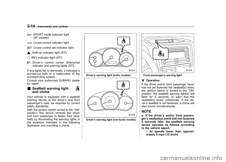
Your vehicle is equipped with a seatbelt
warning device at the driver ’s and front
passenger ’s seat, as required by current
safety standards.
With the ignition switch turned to the “ON ”
position, this device reminds the driver
and front passenger to fasten their seat-
belts by illuminating the warning lights in
the locations indicated in the following
illustration and sounding a chime.
Driver ’s warning light (turbo models)
Driver ’s warning light (non-turbo models)
Front passenger ’s warning light
! Operation
If the driver and/or front passenger have/
has not yet fastened the seatbelt(s) when
the ignition switch is turned to the “ON ”
position, the seatbelt warning light(s) will
flash for 6 seconds, to warn that the
seatbelt(s) is/are unfastened. If the dri-ver ’s seatbelt is not fastened, a chime will
also sound simultaneously. NOTE . If the driver ’s and/or front passen-
ger ’s seatbelt(s) are/is still not fastened
6 seconds later, the seatbelt warning
device operates as follows according
to the vehicle speed.
–At speeds lower than approxi-
mately 9 mph (15 km/h)
Page 138 of 458

is not working properly. Contact your
nearest SUBARU dealer for service im-
mediately. &Rear differential oil
temperature warning
light (STI)
CAUTION
Reduce vehicle speed and park the
vehicle in a safe place as soon as
possible if the R.DIFF TEMP light
illuminates. Continued driving with
this light illuminated can damage
the rear differential and other parts
of the powertrain.
If this light illuminates when the engine is
running, it may indicate that the rear
differential oil temperature is too hot.
At this time, the driver ’s control center
differential will automatically cancel the
current torque-distribution ratio setting and
adopt its minimum ratio.
If the light illuminates while driving, reduce
vehicle speed and stop the vehicle at the
nearest safe place. Park the vehicle for
several minutes. After the light turns off,
you can start driving.
If the light does not turn off, contact the
nearest SUBARU dealer for service. NOTE .
If the tire pressures are not correct
and/or the tires are not all the same
size and brand, the rear differential will
be heavily loaded when the vehicle is
driven, resulting in an abnormally high
oil temperature.. The rear differential oil will deterio-
rate if its temperature increases en-
ough for the rear differential oil tem-
perature warning light to illuminate. It is
advisable to have the rear differential
oil replaced as soon as possible. & Low tire pressure
warning light (U.S.-spec. models)
When the ignition switch is turned to the “ON ”position, the low tire pressure warn-
ing light will illuminate for approximately 2
seconds to check that the tire pressure
monitoring system (TPMS) is functioning
properly. If there is no problem and all tires
are properly inflated, the light will turn off.
Each tire, including the spare (if provided),
should be checked monthly when cold
and inflated to the inflation pressure
recommended by the vehicle manufac-
turer on the vehicle placard or tire inflation
pressure label. (If your vehicle has tires of
a different size than the size indicated on the vehicle placard or tire inflation pres-
sure label, you should determine the
proper tire inflation pressure for thosetires.)
As an added safety feature, your vehicle
has been equipped with a tire pressure
monitoring system (TPMS) that illuminates
a low tire pressure telltale when one or
more of your tires is significantly under-
inflated. Accordingly, when the low tire
pressure telltale illuminates, you should
stop and check your tires as soon as
possible, and inflate them to the proper
pressure. Driving on a significantly under-
inflated tire causes the tire to overheat and
can lead to tire failure. Under-inflation also
reduces fuel efficiency and tire tread life,
and may affect the vehicle
’s handling and
stopping ability.
Please note that the TPMS is not a
substitute for proper tire maintenance,
and it is the driver ’s responsibility to
maintain correct tire pressure, even if
under-inflation has not reached the level
to trigger illumination of the TPMS low tire
pressure telltale.
Your vehicle has also been equipped with
a TPMS malfunction indicator to indicate
when the system is not operating properly.
The TPMS malfunction indicator is com-
bined with the low tire pressure telltale.
When the system detects a malfunction, Instruments and controls
3-19
– CONTINUED –
Page 143 of 458

3-24Instruments and controls
!Vehicle Dynamics Control warning
light (yellow)
CAUTION
The Vehicle Dynamics Control sys-
tem provides its ABS control
through the electrical circuit of the
ABS system. Accordingly, if the ABS
is inoperative, the Vehicle Dynamics
Control system becomes unable to
provide ABS control. As a result, the
Vehicle Dynamics Control system
also becomes inoperative, causing
the warning light to illuminate.
Though both the Vehicle Dynamics
Control and ABS systems are inop-
erative in this case, the ordinary
functions of the brake system are
still available. You will be safe while
driving with this condition, but drive
carefully and have your vehicle
checked at a SUBARU dealer as
soon as possible.
NOTE . If the electrical circuit of the Vehicle
Dynamics Control system itself mal-
functions, the warning light only illumi-
nates. At this time, the ABS (Anti-lock
Brake System) remains fully opera-tional. .
The warning light illuminates when
the electronic control system of the
ABS/Vehicle Dynamics Control systemmalfunctions.
The Vehicle Dynamics Control system is
probably inoperative under any of the
following conditions. Have your vehicle
checked at a SUBARU dealer immedi-
ately. . The warning light does not illuminate
when the ignition switch is turned to the “ ON ”position.
. The warning light illuminates while the
vehicle is running.
NOTE
If the warning light behavior is as
described below, the Vehicle Dynamics
Control system may be considerednormal. . The warning light illuminates right
after the engine is started but turns off
immediately, remaining off.. The warning light illuminates after
engine startup and turns off while the
vehicle is subsequently being driven.. The warning light illuminates during
driving, but it turns off immediately and
remains off. !
Vehicle Dynamics Control OFF in-
dicator light (yellow)
. This light illuminates when the Vehicle
Dynamics Control OFF switch is pressed
(except STI). . This light illuminates when the Vehicle
Dynamics Control mode switch is pressed
for more than 2 seconds (STI). . The light illuminates when the Vehicle
Dynamics Control system is deactivated. NOTE . The light may remain illuminated for
a while after the engine has been
started, especially in cold weather. This
does not indicate the existence of a
problem. The light should turn off as
soon as the engine has warmed up.. The indicator light illuminates when
the engine has developed a problem
and the CHECK ENGINE warning light/
malfunction indicator lamp is on.
The Vehicle Dynamics Control system is
probably malfunctioning under the follow-
ing condition. Have your vehicle checked
at a SUBARU dealer as soon as possible. . The light does not turn off even after
the lapse of several minutes (the engine
has warmed up) after the engine hasstarted.
Page 148 of 458

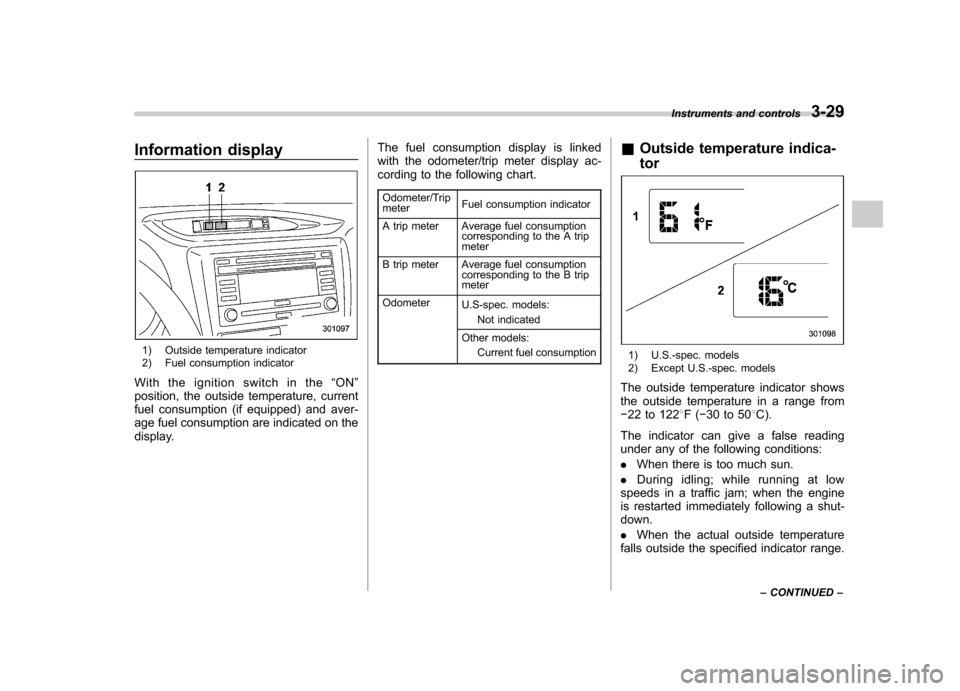
Information display
1) Outside temperature indicator
2) Fuel consumption indicator
With the ignition switch in the “ON ”
position, the outside temperature, current
fuel consumption (if equipped) and aver-
age fuel consumption are indicated on the
display. The fuel consumption display is linked
with the odometer/trip meter display ac-
cording to the following chart.
Odometer/Trip meter Fuel consumption indicator
A trip meter Average fuel consumption corresponding to the A trip meter
B trip meter Average fuel consumption corresponding to the B trip meter
Odometer U.S-spec. models:
Not indicated
Other models: Current fuel consumption &
Outside temperature indica- tor1) U.S.-spec. models
2) Except U.S.-spec. models
The outside temperature indicator shows
the outside temperature in a range from� 22 to 122 8F( �30 to 50 8C).
The indicator can give a false reading
under any of the following conditions: . When there is too much sun.
. During idling; while running at low
speeds in a traffic jam; when the engine
is restarted immediately following a shut- down. . When the actual outside temperature
falls outside the specified indicator range. Instruments and controls
3-29
– CONTINUED –
Page 149 of 458

3-30Instruments and controls
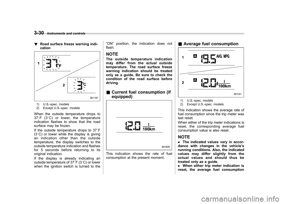
! Road surface freeze warning indi- cation
1) U.S.-spec. models
2) Except U.S.-spec. models
When the outside temperature drops to 37 8F(3 8C) or lower, the temperature
indication flashes to show that the road
surface may be frozen.
If the outside temperature drops to 37 8F
(3 8C) or lower while the display is giving
an indication other than the outside
temperature, the display switches to the
outside temperature indication and flashes
for 5 seconds before returning to its
original indication.
If the display is already indicating an
outside temperature of 37 8F(3 8C) or lower
when the ignition switch is turned to the “
ON ”position, the indication does not
flash. NOTE
The outside temperature indication
may differ from the actual outside
temperature. The road surface freeze
warning indication should be treated
only as a guide. Be sure to check the
condition of the road surface beforedriving. & Current fuel consumption (if equipped)
This indication shows the rate of fuel
consumption at the present moment. &
Average fuel consumption
1) U.S.-spec. models
2) Except U.S.-spec. models
This indication shows the average rate of
fuel consumption since the trip meter was
last reset.
When either of the trip meter indications is
reset, the corresponding average fuel
consumption value is also reset. NOTE . The indicated values vary in accor-
dance with changes in the vehicle ’s
running conditions. Also, the indicated
values may differ slightly from the
actual values and should thus be
treated only as a guide.. When either trip meter indication is
reset, the average fuel consumption