2011 SUBARU IMPREZA battery replacement
[x] Cancel search: battery replacementPage 90 of 458

Keys..................................................................... 2-2
Key number plate ................................................ 2-2
Immobilizer .......................................................... 2-2
Security ID plate .................................................. 2-3
Security indicator light ........................................ 2-3
Key replacement ................................................. 2-3
Door locks ........................................................... 2-4
Locking and unlocking from the outside .. ............ 2-4
Locking and unlocking from the inside ................ 2-5
Battery drainage prevention function ................... 2-5
Power door locking switches ............................. 2-6
Key lock-in prevention function ........................... 2-7
Remote keyless entry system ............................ 2-8
Locking the doors ............................................... 2-9
Unlocking the doors ............................................ 2-9
Opening the trunk lid/unlocking rear gate ........... 2-10
Vehicle finder function ........................................ 2-10
Sounding a panic alarm ...................................... 2-10
Selecting audible signal operation ...................... 2-11
Replacing the battery ......................................... 2-11
Replacing lost transmitters ................................. 2-12 Alarm system
..................................................... 2-16
System operation ............................................... 2-16
Activating and deactivating the alarm system ..... 2-16
If you have accidentally triggered the alarm system ............................................................ 2-17
Arming the system ............................................ 2-17
Disarming the system ........................................ 2-19
Valet mode ........................................................ 2-19
Passive arming .................................................. 2-19
Tripped sensor identification .............................. 2-20
Shock sensors (dealer option).. .......................... 2-20
Child safety locks .............................................. 2-21
Windows ............................................................. 2-21
Power windows ................................................. 2-21
Trunk lid (4-door) ............................................... 2-25
To open and close the trunk lid from outside . ..... 2-25
To open the trunk lid from inside. ....................... 2-25
To lock and unlock the trunk lid release lever ................................................................ 2-25
Internal trunk lid release handle ......................... 2-25
Rear gate (5-door) .............................................. 2-27
Moonroof (if equipped) ...................................... 2-29
Moonroof switches ............................................ 2-29
Sun shade ......................................................... 2-30 Keys and doors
2
Page 100 of 458

&Selecting audible signal op- eration
Using an electronic chirp, the system will
give you an audible signal when the doors
lock and unlock. If desired, you may turn
the audible signal off.
Do the following to deactivate the audible
signal. You can also use the same steps
to restore the function.
1. Sit in the driver ’s seat and shut all
doors and the rear gate.
2. Hold down the REAR (UNLOCK) side
of the power door locking switch.
3. While holding down the REAR (UN-
LOCK) side of the power door locking
switch, pull the key out and re-insert it into
the ignition switch at least 6 times within
10 seconds after Step 2.
4. Open and close the driver ’s door once
within 10 seconds after Step 3.
5. The turn signal lights flash 3 times to
indicate completion of the setting.
You may have the above settings done by
your SUBARU dealer. Also, for models
with the genuine SUBARU navigation
system, the setting can be changed using
the navigation monitor. For details, please
refer to the Owner ’s Manual supplement
for the navigation system. &
Replacing the battery
CAUTION
. Do not let dust, oil or water get on
or in the transmitter when repla-
cing the battery.
. Be careful not to damage the
printed circuit board in the trans-
mitter when replacing the battery.
. Be careful not to allow children to
touch the battery and any re-
moved parts; children could
swallow them.
. There is a danger of explosion if
an incorrect replacement battery
is used. Replace only with the
same or equivalent type of bat-
tery.
. Batteries should not be exposed
to excessive heat such as sun-
shine, fire or the like.
When the transmitter battery begins to get
weak, transmitter range will begin to
decrease. Replace the battery as soon
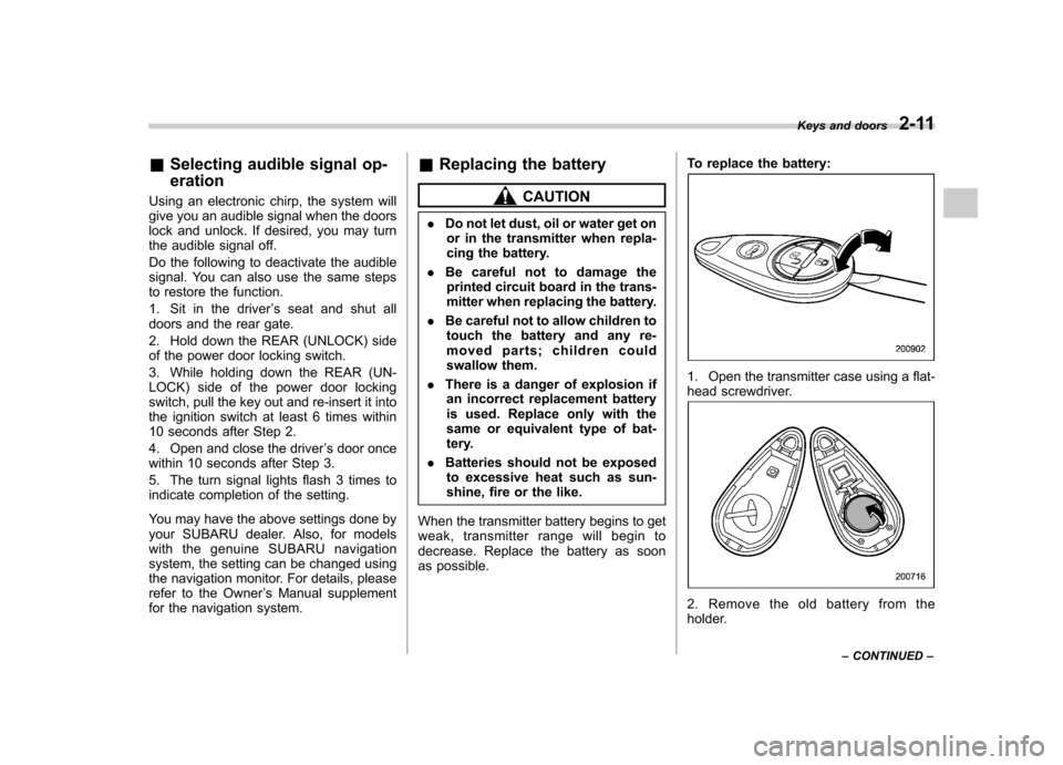
as possible. To replace the battery:
1. Open the transmitter case using a flat-
head screwdriver.
2. Remove the old battery from the
holder.Keys and doors
2-11
– CONTINUED –
Page 111 of 458

2-22Keys and doors
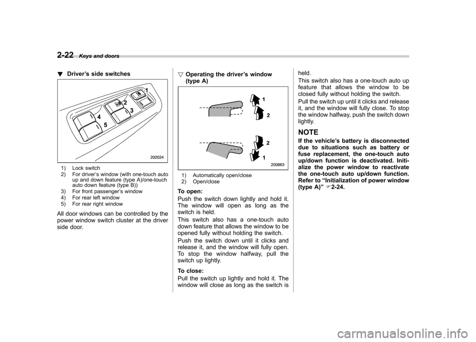
! Driver ’s side switches
1) Lock switch
2) For driver ’s window (with one-touch auto
up and down feature (type A)/one-touch
auto down feature (type B))
3) For front passenger ’s window
4) For rear left window
5) For rear right window
All door windows can be controlled by the
power window switch cluster at the driver
side door. !
Operating the driver ’s window
(type A)
1) Automatically open/close
2) Open/close
To open:
Push the switch down lightly and hold it.
The window will open as long as the
switch is held.
This switch also has a one-touch auto
down feature that allows the window to be
opened fully without holding the switch.
Push the switch down until it clicks and
release it, and the window will fully open.
To stop the window halfway, pull the
switch up lightly.
To close:
Pull the switch up lightly and hold it. The
window will close as long as the switch is held.
This switch also has a one-touch auto up
feature that allows the window to be
closed fully without holding the switch.
Pull the switch up until it clicks and release
it, and the window will fully close. To stop
the window halfway, push the switch down
lightly. NOTE
If the vehicle
’s battery is disconnected
due to situations such as battery or
fuse replacement, the one-touch auto
up/down function is deactivated. Initi-
alize the power window to reactivate
the one-touch auto up/down function.
Refer to “Initialization of power window
(type A) ”F 2-24.
Page 112 of 458

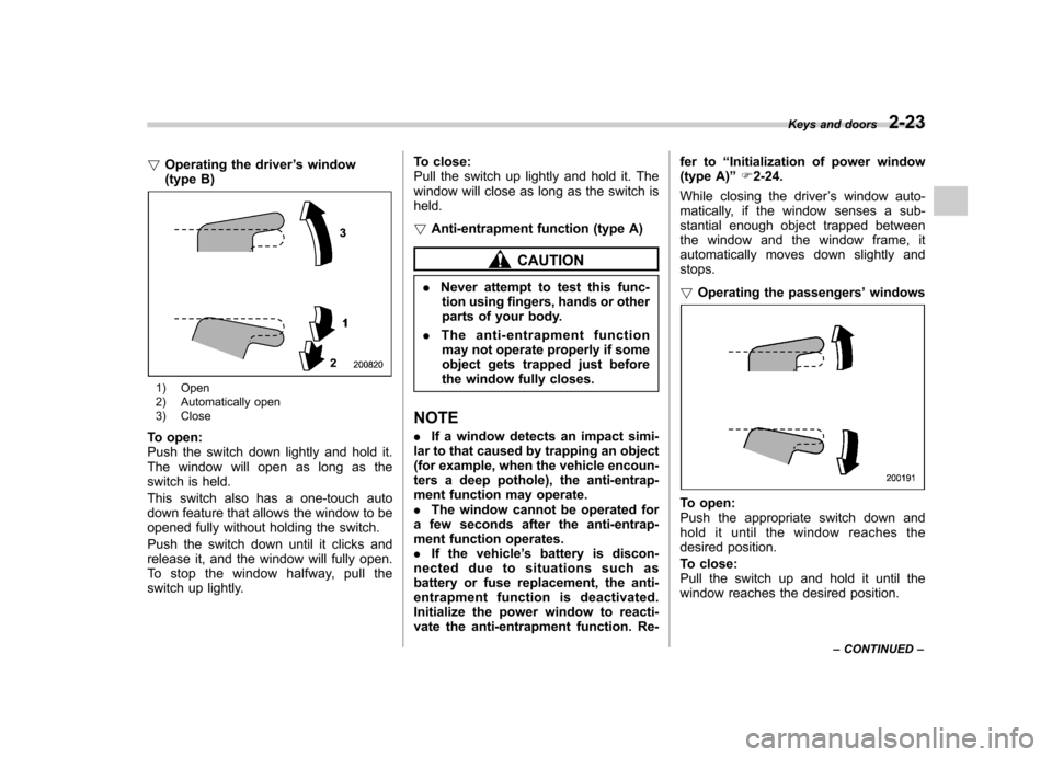
!Operating the driver ’s window
(type B)
1) Open
2) Automatically open
3) Close
To open:
Push the switch down lightly and hold it.
The window will open as long as the
switch is held.
This switch also has a one-touch auto
down feature that allows the window to be
opened fully without holding the switch.
Push the switch down until it clicks and
release it, and the window will fully open.
To stop the window halfway, pull the
switch up lightly. To close:
Pull the switch up lightly and hold it. The
window will close as long as the switch isheld. !
Anti-entrapment function (type A)
CAUTION
. Never attempt to test this func-
tion using fingers, hands or other
parts of your body.
. The anti-entrapment function
may not operate properly if some
object gets trapped just before
the window fully closes.
NOTE . If a window detects an impact simi-
lar to that caused by trapping an object
(for example, when the vehicle encoun-
ters a deep pothole), the anti-entrap-
ment function may operate.. The window cannot be operated for
a few seconds after the anti-entrap-
ment function operates.. If the vehicle ’s battery is discon-
nected due to situations such as
battery or fuse replacement, the anti-
entrapment function is deactivated.
Initialize the power window to reacti-
vate the anti-entrapment function. Re- fer to
“Initialization of power window
(type A) ”F 2-24.
While closing the driver ’s window auto-
matically, if the window senses a sub-
stantial enough object trapped between
the window and the window frame, it
automatically moves down slightly andstops. ! Operating the passengers ’windows
To open:
Push the appropriate switch down and
hold it until the window reaches the
desired position.
To close:
Pull the switch up and hold it until the
window reaches the desired position. Keys and doors
2-23
– CONTINUED –
Page 113 of 458

2-24Keys and doors
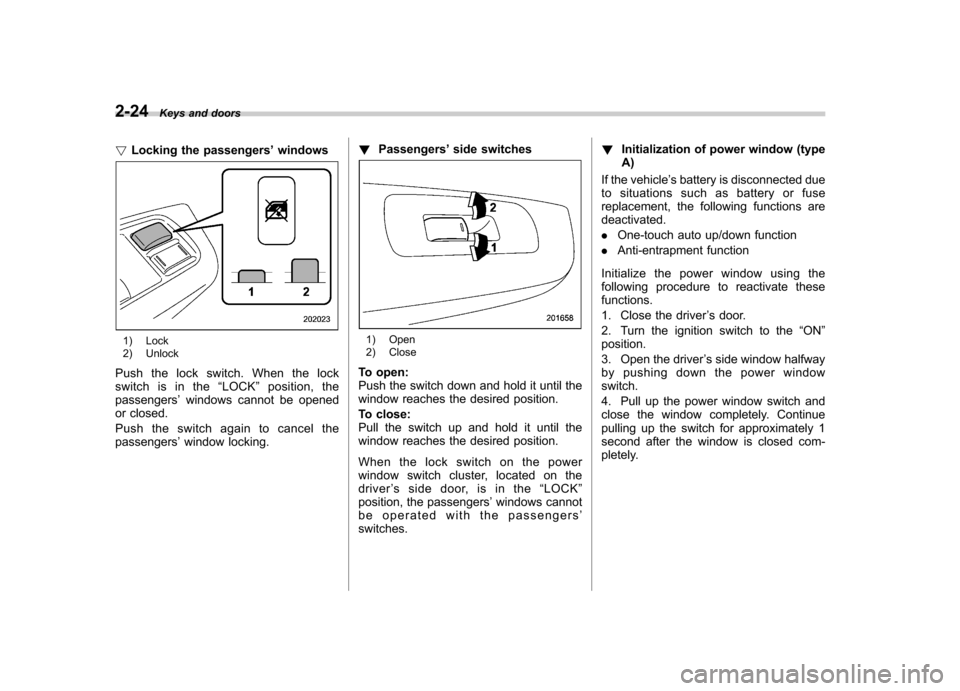
! Locking the passengers ’windows
1) Lock
2) Unlock
Push the lock switch. When the lock
switch is in the “LOCK ”position, the
passengers ’windows cannot be opened
or closed.
Push the switch again to cancel the passengers ’window locking. !
Passengers ’side switches1) Open
2) Close
To open:
Push the switch down and hold it until the
window reaches the desired position.
To close:
Pull the switch up and hold it until the
window reaches the desired position.
When the lock switch on the power
window switch cluster, located on the
driver ’s side door, is in the “LOCK ”
position, the passengers ’windows cannot
be operated with the passengers ’
switches. !
Initialization of power window (typeA)
If the vehicle ’s battery is disconnected due
to situations such as battery or fuse
replacement, the following functions are deactivated. . One-touch auto up/down function
. Anti-entrapment function
Initialize the power window using the
following procedure to reactivate thesefunctions.
1. Close the driver ’s door.
2. Turn the ignition switch to the “ON ”
position.
3. Open the driver ’s side window halfway
by pushing down the power window switch.
4. Pull up the power window switch and
close the window completely. Continue
pulling up the switch for approximately 1
second after the window is closed com-
pletely.
Page 128 of 458

switch is in the“ON ”position.
*3: Turbo models except STI
! Odometer
The odometer shows the total distance
that the vehicle has been driven. !
Double trip meter
The trip meter shows the distance that the
vehicle has been driven since you last set
it to zero.
To set the trip meter to zero, select the A
trip or B trip meter by pushing the knob
and keep the knob pushed for more than 2seconds.
CAUTION
To ensure safety, do not attempt to
change the function of the indicator
during driving, as an accident couldresult.
NOTE
If the connection between the combina- tion meter and battery is broken for any
reason such as vehicle maintenance or
fuse replacement, the data recorded on
the trip meter will be lost. &
Tachometer
The tachometer shows the engine speed
in thousands of revolutions per minute.
CAUTION
Do not operate the engine with the
pointer of the tachometer in the red
zone. This may cause severe da-
mage to the engine.
NOTE
For non-turbo models, to protect the
engine while the select lever is in the“ P ” or “N ” position (for AT models) or
the shift lever is in the neutral position
(for MT models), the engine is con-
trolled so that the engine speed may
not become too high even if the accel-
erator pedal is depressed hard. Instruments and controls
3-9
– CONTINUED –
Page 150 of 458

corresponding to that trip meter indica-
tion is not shown until the vehicle has
subsequently covered a distance of 1
mile (or 1 km). &Turn off display of fuel con-
sumption indicator
The display of the fuel consumption
indicator can be turned off.
To turn off the display of the indicator, turn
the ignition switch to the “LOCK ”position
and press the “+ ” button adjacent to the
information display for approximately 5
seconds. Then, the information display
and the clock display will blink for 3
seconds to notify that the display of the
fuel consumption has been turned off.
To restore the indicator, once again pressthe “+ ” button for approximately 5 sec-
onds. NOTE . The initial display setting of the fuel
consumption indicator of your vehicle
has been set to operational at the time
of shipment from the factory. . The average fuel consumption is
calculated even while the indicator is
not displayed.. Even if you turn off the fuel con-
sumption indicator, the fuel consump-
tion indicator will automatically turn on when the battery voltage is discon-
nected and then reconnected for bat-
tery replacement or fuse replacement.
Light control switch
The light control switch operates when the
key is inserted into the ignition switch.
Regardless of the position of the light
control switch, the illuminated lights are
turned off when the key is removed from
the ignition switch. NOTE
Even if the key is removed from the
ignition switch, the lights can be illu-
minated by operating the light control
switch from
“OFF ”to the “
”or “”
position. In this case, if the driver ’s
door is opened, a chirp sound will
inform the driver that the lights are illuminated.
CAUTION
. Use of any lights for a long period
of time while the engine is not
running can cause the battery todischarge.
. Before leaving the vehicle, make
sure that the light control switch
is turned to the “OFF ”position. If
the vehicle is left unattended for
a long time with the light control
switch set to a position otherthan “OFF ”, the battery may be
Instruments and controls
3-31
– CONTINUED –
Page 276 of 458

not. Remote engine start transmitter pro-
gramming and feature programming can
be adjusted using the following procedure.
1. Open the driver’s door (the driver ’s
door must remain opened throughout the
entire process).
2. Insert the key into the vehicle ’s ignition
switch and turn to the “ON ”position.
3. Locate the small black programming
button behind the fuse box cover, on the
driver ’s side left under the dashboard
panel.
4. Press and hold the black programming
button for 10 to 15 seconds. The horn will
honk and the turn signal lights will flash
three times to indicate that the system has
entered programming mode. At this point
you can proceed to either step 5 or step 6.
5. To program a remote engine start
transmitter: press and release the “
”
button on each transmitter. The horn will
honk and the turn signal lights will flash
one time to indicate a successful trans-
mitter learn each time the “
”button is
pressed. You can program up to eight transmitters.
6. To toggle the Horn Confirmation chirps
ON/OFF: depress and release the brake
pedal to toggle the feature. The horn will
chirp and the turn signal lights will flash
one time to indicate Confirmation Horn
Chirps are “OFF ”. The horn will honk and the turn signal lights will flash 2 times to
indicate Confirmation Horn Chirps are“
ON ”. Depressing the brake pedal repeat-
edly will toggle the feature ON or OFF
each time.
7. To exit the remote engine start trans-
mitter and feature programming mode,
turn the ignition switch to the “LOCK ”
position, remove the key from the ignition
switch and test operation of the remote
engine start transmitter(s) and horn con-
firmation feature.
& System maintenance
! Changing the batteries
CAUTION
. Do not let dust, oil or water get on
or in the remote engine start
transmitter when replacing the
battery.
. Be careful not to damage the
printed circuit board in the re-
mote engine start transmitter
when replacing the battery.
. Be careful not to allow children to
touch the battery and any re-
moved parts; children could
swallow them.
. There is a danger of explosion if an incorrect replacement battery
is used. Replace only with the
same or equivalent type of bat-
tery.
. Batteries should not be exposed
to excessive heat such as sun-
shine, fire or the like.
The two 3-volt lithium batteries (modelCR-1220 ) supplied in your remote engine
start transmitter should last approximately
3 years, depending on usage. When the
batteries begin to weaken, you will notice
a decrease in range (distance from the
vehicle that your remote engine start
system operates). Follow the instructions
below to change the remote engine start
transmitter batteries.
Starting and operating 7-13
– CONTINUED –