2011 SUBARU IMPREZA ignition
[x] Cancel search: ignitionPage 330 of 458

possible because the spare tire is de-
signed only for temporary use.
Check the inflation pressure of the tem-
porary spare tire periodically to keep the
tire ready for use. The correct pressure is
60 psi (420 kPa, 4.2 kg/cm
2).
When using the temporary spare tire, note
the following. . Do not exceed 50 mph (80 km/h).
. Do not put a tire chain on the temporary
spare tire. Because of the smaller tire size,
a tire chain will not fit properly. . Do not use two or more temporary
spare tires at the same time.. Do not drive over obstacles. This tire
has a smaller diameter, so road clearance
is reduced.
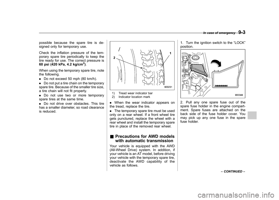
1) Tread wear indicator bar
2) Indicator location mark
. When the wear indicator appears on
the tread, replace the tire. . The temporary spare tire must be used
only on a rear wheel. If a front wheel tire
gets punctured, replace the wheel with a
rear wheel and install the temporary spare
tire in place of the removed rear wheel. & Precautions for AWD models
with automatic transmission
Your vehicle is equipped with the AWD
(All-Wheel Drive) system. In addition, if
your vehicle is an AT model, before driving
your vehicle with the temporary spare tire,
deactivate the AWD capability of the
vehicle as follows. 1. Turn the ignition switch to the
“LOCK ”
position.
2. Pull any one spare fuse out of the
spare fuse holder in the engine compart-
ment. Spare fuses are attached on the
back side of the fuse holder cover. You
may pick up any one fuse in the spare
fuse holder. In case of emergency
9-3
– CONTINUED –
Page 344 of 458

Rear tie-down hooks:
The rear tie-down hooks are located near
each of the jack-up reinforcements.
WARNING
Use the rear tie-down hooks only for
downward anchoring. If they are
used to anchor the vehicle in any
other direction, cables may slip off
the hooks, possibly causing a dan-
gerous situation. &
Using a flat-bed truck
This is the best way to transport your
vehicle. Use the following procedures to
ensure safe transportation.
1. Shift the select lever into the “P ”
position for AT models. Shift the shift lever
into the “1st ”position for MT models.
2. Pull up the parking brake lever firmly.
3. Secure the vehicle onto the carrier
properly with safety chains. Each safety
chain should be equally tightened and
care must be taken not to pull the chains
so tightly that the suspension bottoms out.
CAUTION
If your vehicle has a front under-
spoiler and rear underspoiler (both
optional), be careful not to scrape
them when placing the vehicle on
the carrier and when removing the
vehicle from the carrier.
& Towing with all wheels on the ground
1. Release the parking brake and put the
transmission in the “N ”/neutral position.
2. The ignition switch should be in the“ Acc ”position while the vehicle is being
towed.
3. Take up slack in the towline slowly to
prevent damage to the vehicle. In case of emergency
9-17
– CONTINUED –
Page 345 of 458

9-18In case of emergency
WARNING
. Never turn the ignition switch to
the “LOCK ”position while the
vehicle is being towed because
the steering wheel and the direc-
tion of the wheels will be locked.
. Remember that the brake booster
and power steering do not func-
tion when the engine is not
running. Because the engine is
turned off, it will take greater
effort to operate the brake pedal
and steering wheel.
CAUTION
. If transmission failure occurs,
transport your vehicle on a flat-
bed truck.
. Do not run the engine while being
towed using this method. Trans-
mission damage could result if
the vehicle is towed with the
engine running.
. For models with automatic trans-
mission, the traveling speed
must be limited to less than 20
mph (30 km/h) and the traveling
distance to less than 31 miles (50
km). For greater speeds and distances, transport your vehicle
on a flat-bed truck.
Rear gate
–if the rear gate
cannot be unlocked
In the event that you cannot unlock the
rear gate by operating the power door
locking switches or the remote keyless
entry system, you can unlock it from inside
the cargo area.
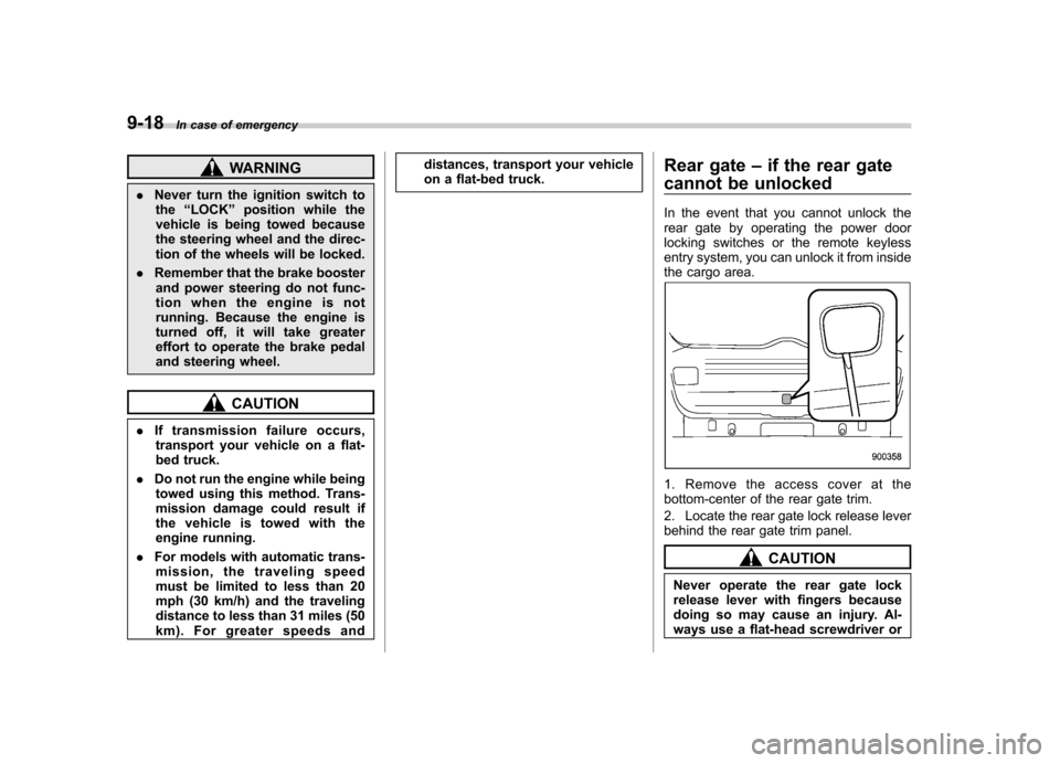
1. Remove the access cover at the
bottom-center of the rear gate trim.
2. Locate the rear gate lock release lever
behind the rear gate trim panel.
CAUTION
Never operate the rear gate lock
release lever with fingers because
doing so may cause an injury. Al-
ways use a flat-head screwdriver or
Page 357 of 458

11-4Maintenance and service
guard against getting oil or fluids
in your eyes. If something does
get in your eyes, thoroughly
wash them out with clean water.
. Do not tamper with the wiring of
the SRS airbag system or seat-
belt pretensioner system, or at-
tempt to take its connectors
apart, as that may activate the
system or it can render it inop-
erative. NEVER use a circuit
tester for this wiring.
If your SRS airbag or seatbelt
pretensioner needs service, con-
sult your nearest SUBARU deal-
er. &
Before checking or servicing
in the engine compartment
WARNING
. Always stop the engine and set
the parking brake firmly to pre-
vent the vehicle from moving.
. Always let the engine cool down.
Engine parts become very hot
when the engine is running and
remain hot for some time after
the engine is stopped.
. Do not spill engine oil, engine
coolant, brake fluid or any other
fluid on hot engine components.
This may cause a fire.
. Always remove the key from the
ignition switch. When the ignition
switch is in the “ON ”position,
thecoolingfanmayoperate
suddenly even when the engine
is stopped.
. Before performing any servicing
on a vehicle equipped with a
remote engine start system (a
dealer option) temporarily place
that system in the service mode
to prevent it from unexpectedly
starting the engine. &
When checking or servicing
in the engine compartment
CAUTION
Do not contact the belt cover while
checking the components in the
engine compartment. Doing so may
cause your hand to slip off the belt
cover and result in an unexpected
injury.
Page 385 of 458

11-32Maintenance and service
temperature outside. By way of example,
the following table shows the required tire
pressures that correspond to various out-
side temperatures when the temperature
in the garage is 60 8F (15.6 8C).
Example:
Tire size: P205/55R16 89V and
P205/50R17 88V
Standard tire pressures:
Front: 33 psi (230 kPa, 2.3 kgf/cm
2)
Rear: 32 psi (220 kPa, 2.2 kgf/cm2)
Garage temperature: 60 8F (15.6 8C)
Outside
temperature Adjusted pressure
[psi (kPa, kgf/cm
2)]
Front Rear
30 8F( �18C) 36 (250, 2.5) 35 (240, 2.4)
10 8F( �12 8C) 38
(265, 2.65) 37
(255, 2.55)
� 10 8F( �23 8C) 40 (280, 2.8) 39 (270, 2.7)
If the low tire pressure warning light
illuminates when you drive the vehicle in
cold outside air after adjusting the tire
pressures in a warm garage, re-adjust the
tire pressures using the method described
above. Then, increase the vehicle speed
to at least 20 mph (32 km/h) and check to
see that the low tire pressure warning light
turns off a few minutes later. If the low tire
pressure warning light does not turn off, the tire pressure monitoring system may
not be functioning normally. In this event,
go to a SUBARU dealer to have the
system inspected as soon as possible.
While the vehicle is driven, friction be-
tween tires and the road surface causes
the tires to warm up. After illumination of
the low tire pressure warning light, any
increase in the tire pressures caused by
an increase in the outside air temperature
or by an increase in the temperature in the
tires can cause the low tire pressure
warning light to turn off.
System resetting is necessary when the
wheels are changed (for example, a
switch to snow tires) and new TPMS
valves are installed on the newly fitted
wheels. Have this work performed by a
SUBARU dealer following wheel replace-ment.
It may not be possible to install TPMS
valves on certain wheels that are on the
market. Therefore, if you change the
wheels (for example, a switch to snow
tires), use wheels that have the same part
number as the standard-equipment
wheels. Without four operational TPMS
valve/sensors on the wheels, the TPMS
will not fully function and the warning light
on the combination meter will illuminate
steadily after blinking for approximatelyone minute.
When a tire is replaced, adjustments are
necessary to ensure continued normal
operation of the tire pressure monitoring
system. As with wheel replacement, there-
fore, you should have the work performed
by a SUBARU dealer.
WARNING
If the low tire pressure warning light
does not illuminate briefly after the
ignition switch is turned ON or the
light illuminates steadily after blink-
ing for approximately one minute,
you should have your Tire Pressure
Monitoring System checked at a
SUBARU dealer as soon as possi-ble.
If this light illuminates while driving,
never brake suddenly and keep
driving straight ahead while gradu-
ally reducing speed. Then slowly
pull off the road to a safe place.
Otherwise an accident involving
serious vehicle damage and serious
personal injury could occur.
If this light still illuminates while
driving after adjusting the tire pres-
sure, a tire may have significant
damage and a fast leak that causes
the tire to lose air rapidly. If you have
Page 399 of 458

11-46Maintenance and service
corresponding fuse. If a fuse has blown,
replace it.
1. Turn the ignition switch to the “LOCK ”
position and turn off all electrical acces- sories.
2. Remove the cover.
3. Determine which fuse may be blown.
Look at the back side of each fuse box
cover and refer to “Fuses and circuits ”
F 12-12.
4. Pull out the fuse with the fuse puller.
5. Inspect the fuse. If it has blown,
replace it with a spare fuse of the samerating.
6. If the same fuse blows again, this
indicates that its system has a problem.
Contact your SUBARU dealer for repairs. Main fuse
Main fuse box
The main fuses are designed to melt
during an overload to prevent damage to
the wiring harness and electrical equip-
ment. Check the main fuses if any
electrical component fails to operate (ex-
cept the starter motor) and other fuses are
good. A melted main fuse must be
replaced. Use only replacements with the
same specified rating as the melted main
fuse. If a main fuse blows after it is
replaced, have the electrical system
checked by your nearest SUBARU dealer. Installation of accessories
Always consult your SUBARU dealer
before installing fog lights or any other
electrical equipment in your vehicle. Such
accessories may cause the electronic
system to malfunction if they are incor-
rectly installed or if they are not suited for
the vehicle.
Page 451 of 458

14-6Index
Heater operation (manual climate control system) .. .......... 4-5
High beam indicator light ............................................ 3-26
High mount stop light ................................................. 11-55
High/low beam change (dimmer) .................................. 3-32
Hill start assist (MT models) ............................... 7-42, 11-29
OFF indicator light .................................................. 3-23
To activate/deactivate ............................................. 7-42
Warning light ................................................. 3-22, 3-22
HomeLink
®................................................................ 3-41
Hook Cargo tie-down ...................................................... 6-13
Shopping bag ........................................................ 6-11
Towing and tie-down ............................................... 9-14
Horn ......................................................................... 3-51
Hose and connections ............................................... 11-14
I
Ignition switch .............................................................. 3-3
Light ....................................................................... 3-5
Illumination brightness control ...................................... 3-33
Immobilizer. ................................................................. 2-2
Indicator light (security indicator light) ....................... 3-25
Indicator light Coolant temperature low ......................................... 3-17
Cruise control ........................................................ 3-26
Cruise control set ................................................... 3-27
Front fog light ........................................................ 3-27
Headlight .............................................................. 3-27
High beam ............................................................ 3-26
Hill start assist OFF ................................................ 3-23
Immobilizer. ........................................................... 3-25 REV.
..................................................................... 3-28
Security ................................................................. 3-25
Select lever/Gear position ........................................ 3-26
Shift-up ................................................................. 3-26
SI-DRIVE .............................................................. 3-26
SPORT mode ........................................................ 3-25
Traction control OFF ............................................... 3-23
Turn signal ............................................................ 3-26
Vehicle Dynamics Control OFF ................................. 3-23
Vehicle Dynamics Control operation .. ........................ 3-23
Information display ...................................................... 3-29
Inside mirror .............................................................. 3-40
Interior lights ............................................................... 6-2
Internal trunk lid release handle .................................... 2-25
iPod
®operations ........................................................ 5-37
J
Jack and jack handle ................................................... 9-5
Jack-up point .............................................................. 9-6
Jump starting ............................................................. 9-11
K
Key............................................................................ 2-2 Number .................................................................. 2-2
Reminder chime ...................................................... 3-5
Replacement. .......................................................... 2-3
L
Leather seat materials ................................................. 10-5
License plate light ..................................................... 11-53
Page 452 of 458

LightBack-up (4-door) ................................................... 11-51
Back-up (5-door) ................................................... 11-52
Brake/Tail and rear side marker (4-door) .................. 11-51
Cargo area .............................................................. 6-2
Control switch ........................................................ 3-31
Dome ..................................................................... 6-2
Front fog ...................................................... 3-36, 11-50
Front position ........................................................ 3-32
High mount stop ................................................... 11-55
Ignition switch .......................................................... 3-5
License plate ........................................................ 11-53
Map ............................................................. 6-3, 11-53
Rear combination .................................................. 11-51
Trunk ................................................................... 11-55
Turn signal ......................................... 3-33, 11-50, 11-51
Limited slip differential (LSD) ....................................... 7-30
Loading your vehicle .................................................. 8-12
Low fuel warning light ......................................... 3-10, 3-22
Low tire pressure warning light .................................... 3-19
Lower and tether anchorage ........................................ 1-29
LSD (Limited slip differential) ....................................... 7-30
M
Main fuse ................................................................. 11-46
Maintenance
Precautions ........................................................... 11-3
Schedule .............................................................. 11-3
Seatbelt ................................................................ 1-19
Tools ...................................................................... 9-4 Malfunction indicator lamp (check engine warning
light) ...................................................................... 3-16
Manual
Climate control system ............................................. 4-3
Transmission oil ........................................... 11-21, 12-8
Transmission-5 speeds ........................................... 7-17
Transmission-6 speeds ........................................... 7-15
Map light ........................................................... 6-3, 11-53
Meters and gauges ...................................................... 3-6
Mirror defogger .......................................................... 3-48
Mirrors ...................................................................... 3-40
Moonroof ........................................................... 2-29, 9-19
N
New vehicle break-in driving ......................................... 8-2
O
Odometer/Trip meter .................................................... 3-8
Off road driving ........................................................... 8-6
Oil filter ................................................................... 11-11
Oil level
Engine ................................................................ 11-10
Front differential gear ............................................ 11-23
Manual transmission ............................................. 11-21
Rear differential gear ............................................ 11-24
Oil pressure warning light ............................................ 3-18
Outside Mirror defogger ...................................................... 3-48
Mirrors .................................................................. 3-47
Temperature indicator .............................................. 3-29
Overheating engine .................................................... 9-13 Index
14-7