2011 SUBARU IMPREZA warning
[x] Cancel search: warningPage 162 of 458
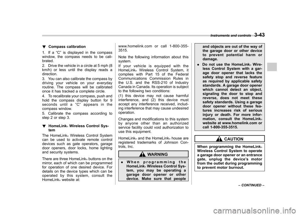
!Compass calibration
1. If a “C ” is displayed in the compass
window, the compass needs to be cali- brated.
2. Drive the vehicle in a circle at 5 mph (8
km/h) or less until the display reads a direction.
3. You can also calibrate the compass by
driving your vehicle on your everyday
routine. The compass will be calibrated
once it has tracked a complete circle.
4. To recalibrate your compass, push and
hold the compass display button for 9
seconds until a “C ” appears in the
compass window.
5. Calibrate the compass according to
step 2 or step 3. ! HomeLink
®Wireless Control Sys-
tem
The HomeLink
®Wireless Control System
can be used to activate remote control
devices such as gate operators, garage
door openers, door locks, home lighting
and security systems.
There are three HomeLink
®buttons on the
mirror, each of which can be programmed
for operation of one desired device. For
details on the device types which can be
operated by this system, consult the HomeLink
®website at: www.homelink.com or call 1-800-355-3515.
Note the following information about this system.
Ifyourvehicleisequippedwiththe HomeLink
®Wireless Control System, it
complies with Part 15 of the Federal
Communications Commission Rules in
the U.S. and the RSS-210 of Industry
Canada in Canada. Its operation is subject
to the following two conditions:
(1) this device may not cause harmful
interference, and (2) this device must
accept any interference received, includ-
ing interference that may cause undesiredoperation.
Changes and modifications to this system
by anyone other than an authorized
service facility could void authorization to
use this equipment. HomeLink
®and the HomeLink®house are
registered trademarks of Johnson Con-
trols, Inc.
WARNING
. When programming the
HomeLink
®Wireless Control Sys-
tem, you may be operating a
garage door opener or other
device. Make sure that people and objects are out of the way of
the garage door or other device
to prevent potential harm ordamage.
. Do not use the HomeLink
®Wire-
less Control System with a gar-
age door opener that lacks the
safety stop and reverse feature
as required by applicable safety
standards. A garage door opener
which cannot detect an object,
signaling the door to stop and
reverse, does not meet these
safety standards. Using a garage
door opener without these fea-
tures increases risk of serious
injury or death. For more infor-
mation, consult the HomeLink
®website at www.homelink.com or
call 1-800-355-3515.
CAUTION
When programming the HomeLink
®Wireless Control System to operate
a garage door opener or an entrance
gate, unplug the device ’s motor
from the outlet during programming
to prevent motor burnout. Instruments and controls
3-43
– CONTINUED –
Page 166 of 458
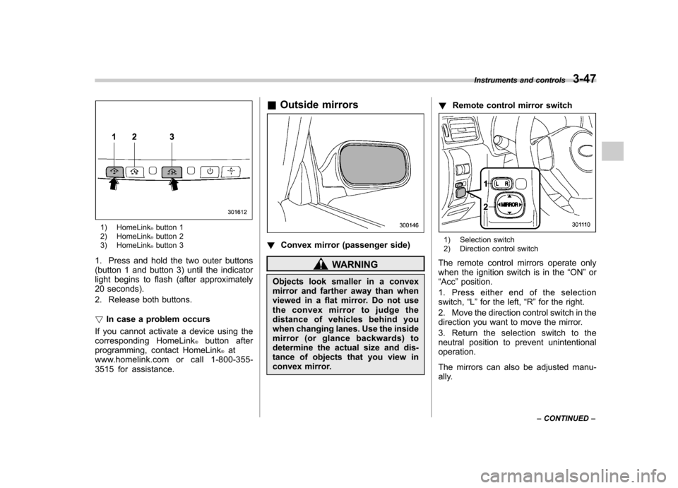
1) HomeLink®button 1
2) HomeLink®button 2
3) HomeLink®button 3
1. Press and hold the two outer buttons
(button 1 and button 3) until the indicator
light begins to flash (after approximately
20 seconds).
2. Release both buttons. ! In case a problem occurs
If you cannot activate a device using the
corresponding HomeLink
®button after
programming, contact HomeLink®at
www.homelink.com or call 1-800-355-
3515 for assistance. &
Outside mirrors
! Convex mirror (passenger side)
WARNING
Objects look smaller in a convex
mirror and farther away than when
viewed in a flat mirror. Do not use
the convex mirror to judge the
distance of vehicles behind you
when changing lanes. Use the inside
mirror (or glance backwards) to
determine the actual size and dis-
tance of objects that you view in
convex mirror. !
Remote control mirror switch
1) Selection switch
2) Direction control switch
The remote control mirrors operate only
when the ignition switch is in the “ON ”or
“ Acc ”position.
1. Press either end of the selectionswitch, “L ” for the left, “R ”for the right.
2. Move the direction control switch in the
direction you want to move the mirror.
3. Return the selection switch to the
neutral position to prevent unintentionaloperation.
The mirrors can also be adjusted manu-
ally. Instruments and controls
3-47
– CONTINUED –
Page 169 of 458
3-50Instruments and controls
CAUTION
. To prevent the battery from being
discharged, do not operate the
defogger and deicer system con-
tinuously for any longer than
necessary.
. Do not use sharp instruments or
window cleaner containing abra-
sives to clean the inner surface
of the rear window. They may
damage the conductors printed
on the window.
NOTE . Turn on the defogger and deicer
system if the wipers are frozen to the windshield.. If the windshield is covered with
snow, remove the snow so that the
windshield wiper deicer works effec-
tively.. While the defogger and deicer sys-
tem is in the continuous operation
mode, if the vehicle speed remains at
9 mph (15 km/h) or less for 15 minutes,
the windshield wiper deicer automati-
cally stops operating, though the rear
window defogger and outside mirror
defogger maintain continuous opera-
tion in this condition. Tilt/telescopic steering wheel
WARNING
. Do not adjust the steering wheel
tilt/telescopic position while driv-
ing. This may cause loss of
vehicle control and result in
personal injury.
. If the lever cannot be raised to
the fixed position, adjust the
steering wheel again. It is dan-
gerous to drive without locking
the steering wheel. This may
cause loss of vehicle control
and result in personal injury.
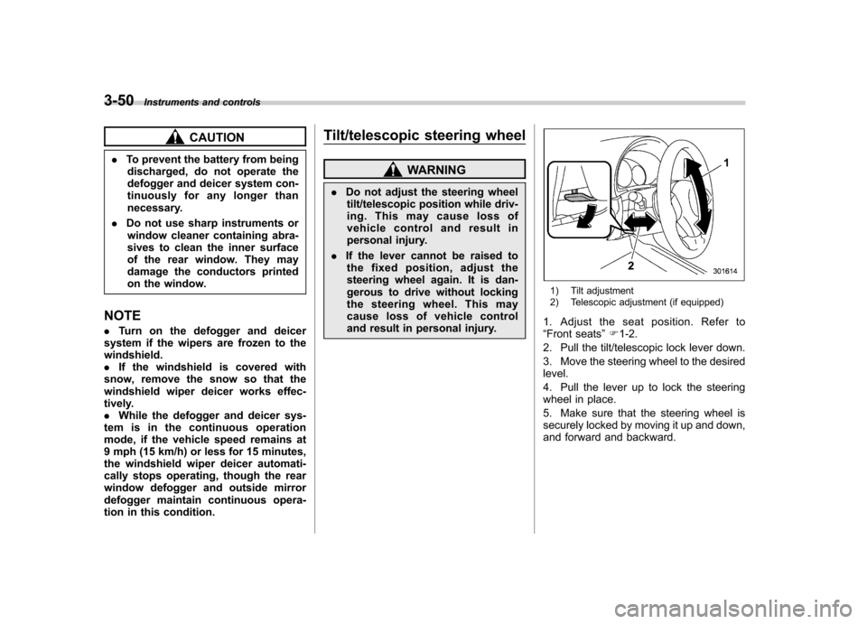
1) Tilt adjustment
2) Telescopic adjustment (if equipped)
1. Adjust the seat position. Refer to “ Front seats ”F 1-2.
2. Pull the tilt/telescopic lock lever down.
3. Move the steering wheel to the desired level.
4. Pull the lever up to lock the steering
wheel in place.
5. Make sure that the steering wheel is
securely locked by moving it up and down,
and forward and backward.
Page 176 of 458
Place the air inlet selection button to the
OFF position when the interior has cooled
to a comfortable temperature and the road
is no longer dusty.
WARNING
Continued operation with the air
inletselectionbuttonintheON
position may fog up the windows.
Switch to the OFF position as soon
as the outside dusty conditionclears.
& Heater operation
NOTE . When the “
”or “”position is
selected, the air conditioner compres-
sor automatically operates regardless
of the position of the air conditioner
button to defog the windshield more
quickly. At the same time, the air inlet
selection is automatically switched to
the OFF position (outside air). How-
ever, the air conditioner indicator light
does not illuminate at this time.. When defrosting, defogging or heat-
ing, warm air is also emitted from the
right and left air outlets. To stop warm
airflow from these outlets, turn the
corresponding thumb wheel down. !
Defrosting or defogging the wind-shield
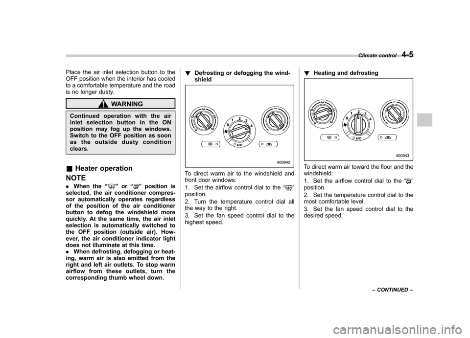
To direct warm air to the windshield and
front door windows:
1. Set the airflow control dial to the “
”
position.
2. Turn the temperature control dial all
the way to the right.
3. Set the fan speed control dial to the
highest speed. !
Heating and defrosting
To direct warm air toward the floor and the windshield:
1. Set the airflow control dial to the “
”
position.
2. Set the temperature control dial to the
most comfortable level.
3. Set the fan speed control dial to the
desired speed. Climate control
4-5
– CONTINUED –
Page 177 of 458
4-6Climate control
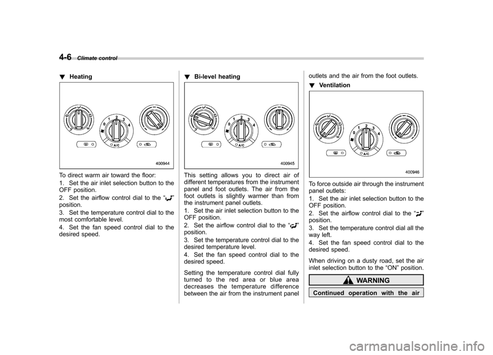
!Heating
To direct warm air toward the floor:
1. Set the air inlet selection button to the
OFF position.
2. Set the airflow control dial to the “
”
position.
3. Set the temperature control dial to the
most comfortable level.
4. Set the fan speed control dial to the
desired speed. !
Bi-level heating
This setting allows you to direct air of
different temperatures from the instrument
panel and foot outlets. The air from the
foot outlets is slightly warmer than from
the instrument panel outlets.
1. Set the air inlet selection button to the
OFF position.
2. Set the airflow control dial to the “
”
position.
3. Set the temperature control dial to the
desired temperature level.
4. Set the fan speed control dial to the
desired speed.
Setting the temperature control dial fully
turned to the red area or blue area
decreases the temperature difference
between the air from the instrument panel outlets and the air from the foot outlets. !
Ventilation
To force outside air through the instrument
panel outlets:
1. Set the air inlet selection button to the
OFF position.
2. Set the airflow control dial to the “
”
position.
3. Set the temperature control dial all the
way left.
4. Set the fan speed control dial to the
desired speed.
When driving on a dusty road, set the air
inlet selection button to the “ON ”position.
WARNING
Continued operation with the air
Page 181 of 458
4-10Climate control
the instrument panel and some through
windshield defroster outlets (A small
amount of air flows to the windshield and
both side windows to prevent fogging.)
(Heat-def): Windshield defroster out-
lets, foot outlets and both side outlets of
the instrument panel
: Windshield defroster outlets and both
side outlets of the instrument panel
For details, refer to “Airflow selection ”F 4-
2. NOTE
When the dial is placed in the “
”or
“” position, the air inlet selection is
automatically set to “outside air ”
mode. &
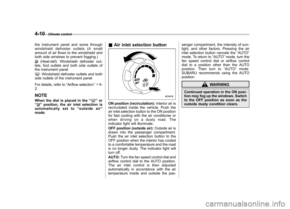
Air inlet selection buttonON position (recirculation): Interior air is
recirculated inside the vehicle. Push the
air inlet selection button to the ON position
for fast cooling with the air conditioner or
when driving on a dusty road. The
indicator light will illuminate.
OFF position (outside air): Outside air is
drawn into the passenger compartment.
Push the air inlet selection button to the
OFF position when the interior has cooled
to a comfortable temperature and the road
is no longer dusty. The indicator light will
turn off. AUTO: Turn the fan speed control dial and
airflow control dial to the AUTO position.
The air inlet control is then adjusted
automatically in accordance with the air
temperature inside and outside the pas- senger compartment, the intensity of sun-
light, and other factors. Pressing the air
inlet selection button cancels the
“AUTO ”
mode. To return to “AUTO ”mode, turn the
fan speed control dial or airflow control
dial to a position other than the AUTO
position. Then turn to “AUTO ”mode.
SUBARU recommends using the AUTOposition.
WARNING
Continued operation in the ON posi-
tion may fog up the windows. Switch
to the OFF position as soon as the
outside dusty condition clears.
Page 235 of 458

5-48Audio
–When the cell phone is too close
to the microphone.
. The sound quality may degrade due
to the influence of the cell phone that is
connected to the system or the circum-
stances of the Bluetooth network. . When another Bluetooth
®device is
simultaneously connected, noise may
be heard in the voice coming from the
hands-free phone. ! Corresponding profiles for the cell phone
. HFP (Hands Free Profile): Ver. 1.0
. OPP (Object Push Profile): Ver. 1.1
& Certification for the Hands-
free system
CAUTION
FCC WARNING
Changes or modifications not ex-
pressly approved by the party re-
sponsible for compliance could void
the user ’s authority to operate the
equipment.
NOTE
This device complies with Part 15 of
the FCC Rules and RSS-Gen of IC Rules. Operation is subject to the
following two conditions: (1) this de-
vice may not cause harmful interfer-
ence, and (2) this device must accept
any interference received, including
interference that may cause undesiredoperation.
NOTE
This equipment has been tested and
found to comply with the limits for a
Class B digital device, pursuant to Part
15 of the FCC Rules. These limits are
designed to provide reasonable protec-
tion against harmful interference in a
residential installation. This equipment
may cause harmful interference to
radio communications, if it is not
installed and used in accordance with
the instructions. However, there is no
guarantee that interference will not
occur in a particular installation. If this
equipment does cause harmful inter-
ference to radio or television reception,
which can be determined by turning the
equipment off and on, the user is
encouraged to try to correct the inter-
ference by one or more of the followingmeasures. . Reorient or relocate the receiving
antenna. . Increase the separation between the equipment and receiver..
Connect the equipment into an out-
let on a circuit different from that to
which the receiver is connected.. Consult the dealer or an experi-
enced radio/TV technician for help.. Changes or modifications not ex-
pressly approved by the party respon-
sible for compliance could void theuser ’s authority to operate the equip-
ment.. This equipment complies with FCC/
IC radiation exposure limits set forth
for an uncontrolled equipment and
meets the FCC radio frequency (RF)
Exposure Guidelines in Supplement C
to OET65 and RSS-102 of the IC radio
frequency (RF) Exposure rules. This
equipment has very low levels of RF
energy that it deemed to comply with-
out maximum permissive exposure
evaluation (MPE). But it is desirable
that it should be installed and operated
keeping the radiator at least 20 cm or
more away from person ’s body (ex-
cluding extremities: hands, wrists, feet
and ankles).. This transmitter must not be co-
located or operated in conjunction with
any other antenna or transmitter.
Page 236 of 458
&Safety precautions
WARNING
. For safety reasons, avoid operat-
ing the cell phone while driving.
. Do not make a phone call while
driving. When you have an in-
coming call, stop the vehicle in a
safe location before taking the
incoming phone call. When you
have to absolutely take a phone
call, tell the caller “I’ ll call you
back ”. And then call the caller
back after stopping the vehicle in
a safe location.
CAUTION
. Do not leave the cell phone in the
vehicle. The temperature in the
vehicle may become extremely
high and cause a malfunction of
the cell phone.
. When using the cell phone, be
careful not to get it close to the
in-vehicle equipment. Getting it
too close to the in-vehicle equip-
ment may result in deterioration
in tone quality or a poor connect-
ing condition. .
In the frequency band used by
this equipment, along with indus-
trial, scientific and medical
equipment such as a microwave
oven, radio stations (a license is
required) to be used by the
production line in the factory to
identify movable bodies, specific
small power radio stations (a
license is not required) and ama-
teur radio stations (a license is
required) are being operated.
(These three types of radio sta-
tions are hereinafter referred toas “other radio stations. ”) Before
using this equipment, be sure to
check to see if “other radio
stations ”are being operated in
the vicinity. If there is detrimental
radio interference from this
equipment to “other radio sta-
tions, ”move the equipment to
another location as soon as
possible to avoid radio interfer-
ence. The frequency band used
by this equipment is in the 2.4
GHz zone. The FH-SS modulation
is employed as a modulation
method. The expected inflicting
interference distance is less than
33 ft (10 m). This equipment uses
a full band and can avoid a band used by a movable body identifi-
cation device.
& Using the Hands-free system
NOTE
You can select the menus by operating the “TUNE/TRACK/CH ”dial or using
the voice command system. Refer to“ Menu list of the Hands-free system ”
F 5-55 or “Voice command system ”
F 5-58.
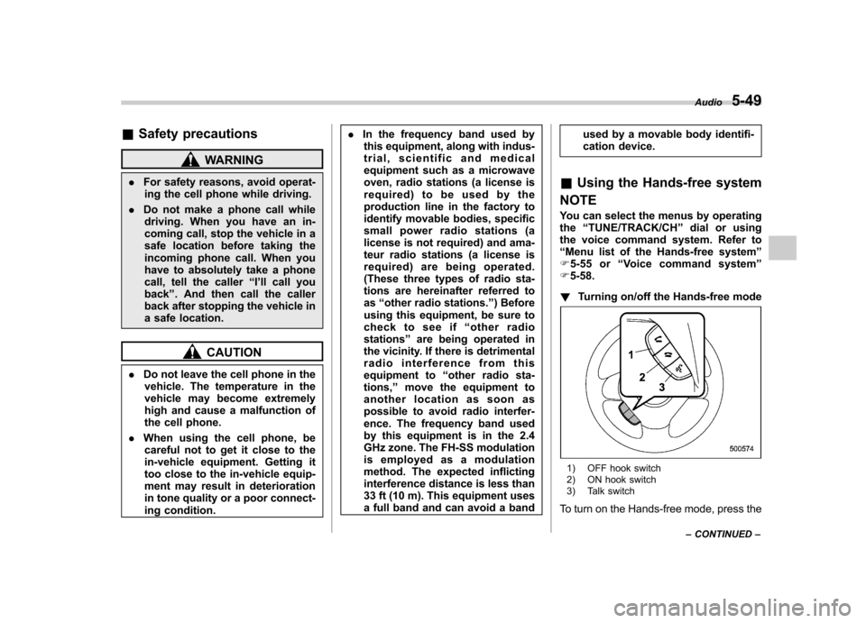
! Turning on/off the Hands-free mode
1) OFF hook switch
2) ON hook switch
3) Talk switch
To turn on the Hands-free mode, press the Audio
5-49
– CONTINUED –