2011 SKODA FABIA instrument cluster
[x] Cancel search: instrument clusterPage 132 of 220
Operating principle
The TCS switches on automatically when the engine is started and then conducts
a self-test. The system monitors the speeds of the driven wheels with the aid of
the ABS sensors. If the wheels are spinning, the force transmitted to the road sur-
face is automatically adapted by reducing the engine speed. The system operates
at all speeds.
The TCS operates in combination with the ABS
⇒ page 131, Antilock brake system
(ABS)
. The TCS will not function if a fault exists in the ABS system.
The TCS warning light lights up in the instrument cluster when there is a fault on
the TCS ⇒ page 24.
During an intervention of the system, the TCS warning light flashes in the in-
strument cluster ⇒ page 25.
Switching off
You can switch the TCS off and on again as you wish by pressing the button
⇒ fig. 118 . The TCS warning light lights up in the instrument cluster when the TCS
is switched off ⇒ page 24.
The TCS should normally always be switched on. It may be good practice in certain
exceptional cases, such as when you wish to have wheel slip, to switch off the
system.
Examples:
● when driving with snow chains,
● when driving in deep snow or on a loose surface,
● when it is necessary to rock a car free when it has become stuck.
then you should switch on the TCS again. WARNING
You should always adjust your style of driving to the conditions of the road
surface and the traffic situation. The increased safety offered must not tempt
you to take greater risks than otherwise - risk of an accident! Note
● All four wheels must be fitted with the same tyres in order to achieve prob-
lem-free operation of the TCS. Differing rolling circumferences of the tyres can
lead to an undesirable reduction in the engine output.
● Changes to vehicle (e.g. on engine, on the brakes, on chassis or another combi-
nation of tyres and wheels) can influence the function of the TCS ⇒ page 169
,
Accessories, changes and replacement of parts.
Brakes What has a negative effect on braking efficiency?
Wear-and-tear
Wear-and-tear to the brake pads is greatly dependent on the operating conditions
of the vehicle and your style of driving. Particularly if you drive a great deal in
towns and over short distances or if you adopt a sporty style of driving, it may be
necessary to have the thickness of the brake pads inspected at a specialist garage
between the service inspections.
Wet roads or road salt
There may be a certain delay before the brakes take full effect under certain con-
ditions such as when driving through water, during heavy rain showers or after
the vehicle has been washed in an automatic vehicle wash, since the brake discs
and brake pads may be moist or even have a coating of ice on them in winter. You
should dry the brakes as soon as possible by applying and releasing the brakes
several times.
There also may be a certain delay before the full braking efficiency is available
when driving on roads which have been treated with road salt if you have not
used the brakes for some considerable time beforehand. The layer of salt on the
brake discs and brake pads must first be rubbed off when you apply the brakes.
Corrosion
Corrosion on the brake discs and dirt on the bake pads occur if the vehicle has
been parked for a long period and if you do not make much use of the braking sys-
tem.
We recommend cleaning the brake discs by firmly applying the brakes at a fairly
high speed if you do not make much use of the braking system or if surface corro-
sion is present ⇒ .
£130
Intelligent Technology
Page 135 of 220
The uphill start assist is active as of a 3 % slope, if the driver door is closed. It is
always active on slopes when in forward or reverse start off. When driving down-
hill, it is inactive.
Electrohydraulic power steering The power steering enables you to steer the vehicle with less physical force.
The steering characteristics can be changed by a specialist garage.
You will place great stresses on the power steering system if the steering is
turned to full lock when the vehicle is stationary. Turning the steering to full lock
in such a situation will be accompanied by noises.
It is still possible to fully steer the vehicle if the power steering fails or if the en-
gine is not running (vehicle being towed in). The only difference is that greater
physical effort is required.
It is possible that the hydraulic pump of the power steering will not run due to the
low vehicle network voltage if the battery has gone flat and the engine must star-
ted with the help off jump leads. This condition will be indicated by lighting up of
the warning light.
The power steering operates again if the battery is charged to a specific range
when engine is running. It also operates again, if the engine can be started with
its own battery.
If there is a fault in the power steering, the warning light lights up in the instru-
ment cluster
⇒ page 20. WARNING
Contact your specialist garage if the power steering is defective. CAUTION
Never leave the steering wheel at full lock for more than 15 seconds when the en-
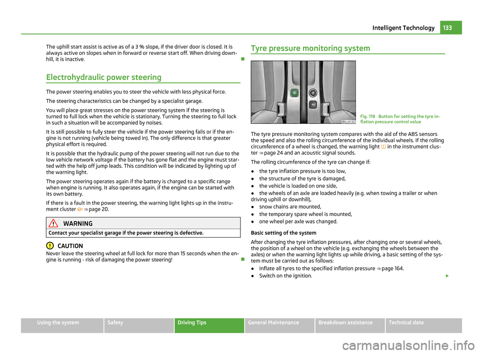
gine is running - risk of damaging the power steering! Tyre pressure monitoring system Fig. 119 Button for setting the tyre in-
flation pressure control value
The tyre pressure monitoring system compares with the aid of the ABS sensors
the speed and also the rolling circumference of the individual wheels. If the rolling
circumference of a wheel is changed, the warning light in the instrument clus-
ter ⇒ page 24 and an acoustic signal sounds.
The rolling circumference of the tyre can change if:
● the tyre inflation pressure is too low,
● the structure of the tyre is damaged,
● the vehicle is loaded on one side,
● the wheels of an axle are loaded heavily (e.g. when towing a trailer or when
driving uphill or downhill),
● snow chains are mounted,
● the temporary spare wheel is mounted,
● one wheel per axle was changed.
Basic setting of the system
After changing the tyre inflation pressures, after changing one or several wheels,
the position of a wheel on the vehicle (e.g. exchanging the wheels between the
axles) or when the warning light lights up while driving, a basic setting of the sys-
tem must be carried out as follows:
● Inflate all tyres to the specified inflation pressure ⇒ page 164.
● Switch on the ignition. £ 133
Intelligent Technology Using the system Safety Driving Tips General Maintenance Breakdown assistance Technical data
Page 145 of 220

Driving Tips
–
Do not, as far as possible, drive with your vehicle unladen and the trailer laden.
– Do not make full use of the legal maximum speeds. This applies in particular to
downhill sections.
– Apply the brakes in good time.
– Keep a check on the coolant temperature gauge if the outside temperature is
high.
Distribution of weight
The distribution of the weight is very poor if your vehicle is unladen and the trailer
is laden. Maintain a particularly low speed if you cannot avoid driving with this
combination.
Driving speed
Do not drive faster than 80 km/h for safety reasons. This also applies for countries
in which higher speeds are allowed.
The fact that the driving stability of the vehicle + trailer combination reduces with
increasing speed means that the legally allowed speed should not be used when
there are unfavourable road, weather or wind conditions, particularly near acci-
dent black spots.
You must always reduce your speed immediately as soon as you detect even just
the slightest swaying
of the trailer. On no account attempt to stop the trailer
from “swaying” by accelerating.
Apply the brakes in good time! If the trailer is fitted with a trailer brake, apply the
brakes gently at first and then brake firmly. This will avoid brake jolts resulting
from the trailer wheels locking. Shift down gears in good time before negotiating
a downhill section to allow the engine to also act as a brake.
Engine overheating
Please keep a check on the coolant temperature gauge if you have to negotiate a
lengthy slope in a low gear at a high engine speed when the outside temperature
is very high ⇒ page 11.
If the needle of the coolant temperature gauge moves into the right-hand area or
even the red area of the scale, reduce your speed immediately. Stop and switch
off the engine if the warning light in the instrument cluster begins flashing.
Wait a few minutes and check the level of coolant in the coolant expansion bottle
⇒ page 157, Inspecting the coolant level. Please refer to the following guidelines
⇒ page 23
, Coolant temperature/ Coolant
quantity .
The coolant temperature can be reduced by switching on the heating.
Any increase in the cooling effect of the coolant fan through shifting down a gear
and increasing the engine speed is not possible since the fan speed is independ-
ent of the engine speed. One should also not drop a gear for this reason when
towing a trailer as long as the engine can manage the slope without any drop in
speed. 143
Towing a trailer Using the system Safety Driving Tips General Maintenance Breakdown assistance Technical data
Page 157 of 220

Engine coolant expansion reservoir
. . . . . . . . . . . . . . . . . . . . . . . . . . . . . . . . . . . 157
Windshield washer fluid reservoir . . . . . . . . . . . . . . . . . . . . . . . . . . . . . . . . . . . . . 163
Engine oil filler opening . . . . . . . . . . . . . . . . . . . . . . . . . . . . . . . . . . . . . . . . . . . . . . . . 156
Engine oil dipstick . . . . . . . . . . . . . . . . . . . . . . . . . . . . . . . . . . . . . . . . . . . . . . . . . . . . . . 155
Brake fluid reservoir . . . . . . . . . . . . . . . . . . . . . . . . . . . . . . . . . . . . . . . . . . . . . . . . . . . . 159
Battery (below a cover) . . . . . . . . . . . . . . . . . . . . . . . . . . . . . . . . . . . . . . . . . . . . . . . . . 159Note
The location of the inspection points in the engine compartment of petrol and die-
sel engines is practically identical.
Engine oil Check engine oil level The dipstick indicates the level of oil in the engine.
Fig. 129 Dipstick
Checking the oil level
– Ensure that the vehicle is positioned on a level surface and the engine has
reached its operating temperature ⇒ .
– Switch the engine off.
– Open the bonnet ⇒ in Working in the engine compartment on page 154.
– Wait a few minutes until the engine oil flows back into the oil sump. Take out
the dipstick.
– Wipe off the dipstick with a clean cloth and insert it again fully.
– Then withdraw the dipstick again and read off the oil level.
1 2
3
4
5
6 Oil level within range
a –
You must not top up the oil.
Oil level within range b –
You may top up the oil. It is possible that the oil level may then be within
range a after doing this.
Oil level within range c –
You must top up the oil ⇒ page 156. It is sufficient, once this is done, to keep
the oil level is within range b .
It is normal for the engine to consume oil. The oil consumption may be as much as
0.5 l/1 000 km depending on your style of driving and the conditions under which
you operate your vehicle. The oil consumption may be slightly higher than this
during the first 5 000 kilometres.
One should therefore check the oil level at regular intervals, preferably every time
after the fuel tank is filled or after driving for long stretches.
We recommend maintaining the oil level within the range a if the engine has
been operating at high loads, for example during a lengthy motorway trip during
the summer months, towing a trailer or negotiating a high mountain pass, but not
above this .
The warning light in the instrument cluster will indicate whether the oil level is
too low ⇒ page 23, Engine oil . In this case, check the oil level as soon as
possible. Top up with an appropriate quantity of oil. CAUTION
● Always check the oil level on vehicles with engine 1.2 l/44 kW when the engine
is cold. Otherwise the measuring result is incorrect und oil could be incorrectly re-
plenished - risk of engine damage!
● The oil level must on no account extend beyond the range A . Danger of dam-
aging the catalytic converter.
● Do not continue your journey if for some reason it is not possible under the
conditions prevailing to top up with oil. Switch the engine off and obtain profes-
sional assistance from a specialist garage, otherwise it could lead to severe en-
gine damage. Note
Engine oil specifications ⇒ page 195. 155
Inspecting and Replenishing Using the system Safety Driving Tips General Maintenance Breakdown assistance Technical data
Page 159 of 220
When refilling, we only recommend you use the same antifreeze described on the
antifreeze expansion tank.
Please contact an authorised
ŠKODA
Service Partner if you have any questions re-
garding the coolant or if you wish to fill up with a different coolant.
An authorised ŠKODA Service Partner can also supply you with the correct coolant
additives.
Coolant capacity Petrol engines Capacities (in liter)
1.2 ltr./44 kW - EU5 5,5
1.2 l/51 kW - EU5 / EU2 DDK 5,5
1.2 ltr./63 kW TSI - EU5 7,7
1.2 ltr./77 kW TSI - EU5 7,7
1.4 ltr./63 kW - EU5 5,5
1.4 ltr./132 kW TSI - EU5 6,6
1.6 ltr./77 kW - EU4/EU2 DDK 5,5
Diesel engines Capacities (in liter)
1.2 ltr./55 kW TDI CR DPF - EU5 6,6
1.6 ltr./55 kW TDI CR DPF - EU5 8,4
1.6 ltr./66 kW TDI CR DPF - EU5 8,4
1.6 ltr./77 kW TDI CR DPF - EU5 8,4
CAUTION
● Other coolant additives may cause operational problems which, in particular,
involves significantly reducing the anticorrosion effect.
● Any faults or problems resulting from corrosion may cause a loss of coolant
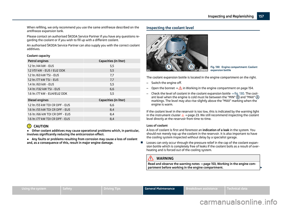
and, as a consequence of this, result in major engine damage. Inspecting the coolant level Fig. 130 Engine compartment: Coolant
expansion bottle
The coolant expansion bottle is located in the engine compartment on the right.
– Switch the engine off.
– Open the bonnet ⇒ in Working in the engine compartment on page 154.
– Check the level of coolant in the coolant expansion bottle ⇒ fig. 130. The cool-
ant level when the engine is cold must lie between the “MIN” B and “MAX”
A markings. The level may also rise slightly above the “MAX” marking when the
engine is warm.
If the coolant level in the reservoir is too low, this is indicated by the warning light
in the instrument cluster
⇒ page 23. We still recommend inspecting the coolant
level directly at the reservoir from time to time.
Loss of coolant
A loss of coolant is first and foremost an indication of a leak in the system. You
should not merely top up the coolant in the reservoir. It is also important to have
the cooling system inspected without delay by a specialist garage.
Losses can only occur through the pressure relief in the cap of the coolant expan-
sion bottle which is completely free of leaks if the coolant boils as a result of over-
heating and is forced out of the cooling system. WARNING
Read and observe the warning notes ⇒ page 153,
Working in the engine com-
partment before working in the engine compartment. £ 157
Inspecting and Replenishing Using the system Safety Driving Tips General Maintenance Breakdown assistance Technical data
Page 161 of 220

Brake fluid
Inspecting the brake fluid level Fig. 131 Engine compartment: Brake flu-
id reservoir
The brake fluid reservoir is located on the left of the engine compartment. The
brake fluid reservoir on right-hand steering models is positioned on the other side
of the engine compartment.
– Switch the engine off.
– Open the bonnet ⇒ in Working in the engine compartment on page 154.
– Inspect the brake fluid level in the reservoir ⇒ fig. 131 . The level must be be-
tween the “MIN” and “MAX” markings.
A slight drop in the fluid level results when driving due to normal wear-and-tear
and automatic adjustment of the brake pads, and is perfectly normal.
There may be an indication of a leak in the brake system, however, if the fluid lev-
el drops significantly within a short time or if it drops below the “MIN” marking. If
the brake fluid level is too low, this is indicated by the warning light lighting up
in the instrument cluster ⇒ page 26. In this case stop immediately and do not
drive any further! Obtain professional assistance. WARNING
● Read and observe the warning notes ⇒
page 153, Working in the engine
compartment before working in the engine compartment.
● If the fluid level has dropped below the MIN marking, do not drive any fur-
ther - risk of accident! Contact a Škoda dealer to obtain professional assis-
tance. Replacing brake fluid Brake fluid absorbs moisture. This causes the fluid to absorb moisture from the
surrounding air over a period of time. Excessive water in the brake fluid may be
the cause of corrosion in the brake system. The water content also lowers the
boiling point of the brake fluid.
Only new genuine brake fluid from
ŠKODA may be used. The brake fluid must
comply with one of the following standards or specifications:
● VW 501 14,
● FMVSS 116 DOT4,
● DIN ISO 4925 CLASS 4.
We recommend that you have the brake fluid replaced by an authorised ŠKODA
Service Partner as part of an Inspection Service. WARNING
● Using old brake fluid can result in severe stress on the brakes because of
the formation of vapour bubbles in the brake system. This greatly impairs the
braking efficiency and thus also the safety of your vehicle. CAUTION
Brake fluid damages the paintwork of the vehicle. For the sake of the environment
Due to issues with disposal, the special tools and knowledge required, we recom-
mend you have the brake fluid replaced by an authorised ŠKODA Service Partner.
Battery General information Improper handling of the vehicle battery can cause damage. We therefore recom-
mend you have work on the vehicle battery carried out by an authorised
ŠKODA
Service Partner.
There is a risk of injuries, scalding, accidents and burns when carrying out any
work on the battery and on the electrical system. For this reason, it is essential to
comply with the warning instructions ⇒ stated below and with the general ap-
plicable rules of safety. £ 159
Inspecting and Replenishing Using the system Safety Driving Tips General Maintenance Breakdown assistance Technical data
Page 185 of 220

Fuse assignment in the dash panel
Fig. 152 Schematic representation of the fuse box for vehicles with left-hand steering/right-
hand steering
Certain electrical components are only standard on certain vehicle model versions
or only suppliable as optional equipment for certain models. No. Power consumer
1 S-contact
2 START - STOP
3 Instrument cluster, headlight range adjustment
4 ABS control unit
5 Petrol engine: Speed regulating system
6 Reversing light (manual gearbox)
7 Ignition
Engine control unit, automatic gearbox
8 Brake pedal switch, coolant fan
9 Operating controls for the heating, control unit for air conditioning sys-
tem, parking aid, control unit for cornering lights, coolant fan
10 The air conditioning system
11 Mirror adjustment
12 Control unit for trailer detection
13 Control unit for automatic gearbox
14 Motor for halogen projector headlights with cornering light function
15 Radio navigation system PDA
16 Electrohydraulic power steering No. Power consumer
17 START - STOP - radio
Daylight driving lights
18 Mirror heater
19 S-contact
20 Anti-theft alarm system
21 Reversing light, fog lights with the function “CORNER”
22 Operating controls for the heating, control unit for air conditioning sys-
tem, parking aid, mobile phone, instrument cluster, steering angle
sender, ESP, vehicle voltage control unit, multifunction steering wheel
23 Interior lighting, storage compartment and luggage compartment, side
lights
24 Central control unit of the vehicle
25 Seat heaters
26 Rear window wiper
27 Telephone preinstallation
28 Petrol engine: AKF valve, petrol engine: Control flap
29 Injection, water pump
30 Fuel pump
Ignition
Cruise control system, operation of PTC relay
31 Lambda probe
32 High pressure pump, pressure valve
33 Engine control unit
34 Engine control unit
Vacuum pump
35 Power supply of ignition lock
36 Main beam
37 Rear fog light
38 Fog lights
39 Blower
40 Heatable windscreen washing nozzles, windscreen cleaning system
41 Not assigned
42 Rear window heater
£ 183
Fuses and light bulbs Using the system Safety Driving Tips General Maintenance Breakdown assistance Technical data
Page 186 of 220

No. Power consumer
43 Horn
44 Front window wiper
45 Central control unit for convenience system
46 Engine control unit
Engine control unit
Fuel pump relay
Fuel pump control unit
47 Cigarette lighter, power socket in the luggage compartment
a)48 ABS, START-STOP - DC/DC converter ESP
49 Turn signal lights, brake lights
50 START-STOP - DC/DC converter infotainment
Radio
51 Electrical power window (front and rear) - left side
52 Electrical power window (front and rear) - right side
53 Parking light - left side
Electric sliding/tilting roof
54 START-STOP - instrument cluster
Anti-theft alarm system
55 Control unit for automatic gearbox DSG
56 Headlight cleaning system
Parking light - right side
57 Left low beam, headlight range adjustment
58 Low beam on the right
a)
If the engine is switched off already one electrical component which is connected can discharge the
battery. Replacing fuses at the battery (manual gearbox, automatic
gearbox DSG) Fig. 153 The battery: fuse cover
– Press together the interlocks of the fuse cover simultaneously in direction of
arrow A ⇒ fig. 153 and push out the cover in direction of arrow
B .
– Release the fixtures in the openings C using a flat screwdriver and fold the
cover upwards in direction of arrow D .
– Find out which fuse belongs to the component which is not operating.
– Defect fuses can be detected by their melted metal strips. Replace the defect
fuse by a new fuse of the same ampere number. WARNING
Read and observe the warning notes ⇒ page 153, Working in the engine com-
partment before working in the engine compartment. CAUTION
● Never attempt to “
repair” fuses and also do not replace them with a fuse of a
higher amperage - risk of fire! This may also cause damage at another part of the
electrical system.
● Have the electrical system checked as quickly as possible by a specialist ga-
rage if a newly inserted fuse blows again after a short time. Note
We recommend that you have these fuses replaced by a specialist garage. 184
Fuses and light bulbs