2011 Seat Ibiza ST brake
[x] Cancel search: brakePage 220 of 280

218Checking and refilling levels
195/65 R15 91T
This contains the following information: Tyre width in mm
Height/width ratio in %
Tyre construction: Radial
Rim diameter in inches
Load rating code
Speed rating
The tyres could also have the following information:
● A direction of rotation symbol
● “Reinforced” denotes heavy-duty tyres.
The manufacturing date is also indicated on the tyre sidewall (possibly only
on the inner side of the wheel).
“DOT ... 1103 ...” means, for example, that the tyre was produced in the
11th week of 2003.
We recommend that work on tyres and wheels be carried out by an Author-
ised Service Centre. They are familiar with the procedure and have the nec-
essary special tools and spare parts as well as the proper facilities for dis-
posing of the old tyres.
Any Authorised Service Centre has full information on the technical require-
ments when installing or changing tyres, wheels or wheel trims. 195
65
R
15
91
T
WARNING
● We recommend that you use only wheels and tyres which have been
approved by SEAT for your model. Failure to do so could impair vehicle
handling. Risk of accident.
● Avoid running the vehicle on tyres that are more than 6 years old. If
you have no alternative, you should drive slowly and with extra care at all
times.
● Never use old tyres or those with an unknown history of use.
● If wheel trims are retrofitted, you must ensure that the flow of air to
the brakes is not restricted. This could cause them to overheat.
● All four wheels must be fitted with radial tyres of the same type, size
(rolling circumference) and the same tread pattern.
For the sake of the environment
Old tyres must be disposed of according to the laws in the country con-
cerned.
Note
● For technical reasons, it is not generally possible to use the wheels from
other vehicles. This can also apply to wheels of the same model. The use of
wheels or tyres which have not been approved by SEAT for use with your
model may invalidate the vehicle's type approval for use on public roads.
● If the spare tyre is not the same as the tyres that are mounted on the
vehicle (e.g. winter tyres) you should only use the spare tyre for a short peri-
od of time and drive with extra care. Refit the normal road wheel as soon as
possible.
Page 221 of 280

219
Checking and refilling levels
Wheel bolts
Wheel bolts must be tightened to the correct torque.
The design of wheel bolts is matched to the rims. If different wheel rims are
fitted, the correct wheel bolts with the right length and correctly shaped
bolt heads must be used. This ensures that wheels are fitted securely and
that the brake system functions correctly.
In certain circumstances, you should not use wheel bolts from a different
vehicle, even if it is the same model ⇒ page 189.
WARNING
If the wheel bolts are not tightened correctly, the wheel could become
loose while driving. Risk of accident.
● The wheel bolts must be clean and turn easily. Never apply grease or
oil to them.
● Use only wheel bolts which belong to the wheel.
● If the prescribed torque of the wheel bolts is too low, they could loos-
en whilst the vehicle is in motion. Risk of accident! If the tightening tor-
que is too high, the wheel bolts and threads can be damaged.
CAUTION
The prescribed torque for wheel bolts for steel and alloy wheels is 120 Nm. Winter tyres
Winter tyres will improve the vehicles handling on snow and
ice.
In winter conditions winter tyres will considerably improve the vehicle's han-
dling. The design of summer tyres (width, rubber compound, tread pattern)
gives less grip on ice and snow.
Winter tyres must be inflated to a pressure 0.2 bar higher than the pres-
sures specified for summer tyres (see sticker on tank flap).
Winter tyres must be fitted on all four wheels.
Information on permitted winter tyre sizes can be found in the vehicle's reg-
istration documents. Use only radial winter tyres. All tyre sizes listed in the
vehicle documentation also apply to winter tyres.
Winter tyres lose their effectiveness when the tread is worn down to a depth
of 4 mm.
The speed rating code ⇒ page 217, New tyres and wheels determines the
following speed limits for winter tyres: ⇒
Qmax. 160 km/hSmax. 180 km/hTmax. 190 km/hHmax. 210 km/h
In some countries, vehicles which can exceed the speed rating of the fitted
tyre must have an appropriate sticker in the driver's field of view. These
stickers are available from your Authorised Service Centre. The legal require-
ments of each country must be followed.
Do not have winter tyres fitted for unnecessarily long periods. Vehicles with
summer tyres handle better when the roads are free of snow and ice.
Safety FirstOperating InstructionsPractical TipsTechnical Specifications
Page 224 of 280

222If and when
If you have a puncture on one of the front wheels when using snow chains,
fit the compact temporary spare in place of one of the rear wheels. You can
then attach the snow chains to the wheel taken from the rear and use this
wheel to replace the punctured front wheel.
WARNING
● The tyre pressures must be checked and corrected as soon as possi-
ble.
● Do not drive faster than 80 km/h. Higher speeds can cause an acci-
dent.
● Avoid heavy acceleration, hard braking and fast cornering. Risk of ac-
cident.
● Never use two or more compact spare tyres at the same time, risk of
accident.
● No other type of tyre (normal summer or winter tyre) may be fitted on
the compact temporary spare wheel rim.
Tyre repair kit*
The tyre repair kit (for vehicles not including a spare wheel)
is stored under the floor panel in the luggage compartment. Your vehicle is equipped with the Tyre Mobility System “Tyre repair kit”.
The tyre repair kit consists of a container with sealing compound to repair
the puncture and a compressor to generate the required tyre pressure. The
kit will reliably seal punctures up to a size of about 4 mm caused by the
penetration of a foreign body into the tyre.
Note
● Seek professional assistance if the repair of a tyre puncture is not possi-
ble with the sealing compound. Wheel change
Preparation work
What you must do before changing a wheel.
– If you have a flat tyre or puncture, park the vehicle as far away
from the flow of traffic as possible. Choose a location that is as
level as possible.
– All passengers should leave the vehicle. They should wait in a
safe area (for instance behind the roadside crash barrier).
– Switch the engine off. Switch the hazard warning lights on and
place the warning triangles in position.
– Apply the handbrake firmly.
– Engage the first gear , or put the selector lever to position P for
those vehicles with an automatic gearbox.
– If you are towing a trailer, unhitch it from your vehicle.
– Take the vehicle tools and the spare wheel out of the luggage
compartment.
WARNING
Switch on the hazard warning lights and place the warning triangles in
position. This is for your own safety and also warns other road users.
Page 230 of 280
228If and when
Note
● If sealant should leak out, leave it to dry. This way you can pull it off like
a piece of foil.
● Observe the expiry date stated on the sealing compound can. Have the
sealing compound exchanged by a specialised workshop.
● Seek professional assistance if the repair of a tyre puncture is not possi-
ble with the sealing compound.
What to do first
Certain steps must be taken before repairing a tyre.
– If you have a flat tyre or puncture, park the vehicle as far away
from the flow of traffic as possible.
– Apply the handbrake firmly.
– Engage first gear , or put the selector lever to position P.
– All passengers should leave the vehicle. They should wait in a
safe area (for instance behind the roadside crash barrier).
– Check whether a repair is possible using the Tyre Mobility Sys-
tem “General information and safety notes.”
– Unscrew inflation cap from the affected wheel.
– Take the tyre repair kit out of the luggage compartment.
WARNING
Switch on the hazard warning lights and place the warning triangles in
position. This is for your own safety and also warns other road users.
CAUTION
Take special care if you have to repair a tyre on a slope.
Note
● Please observe legal requirements when doing so.
● Remember to replace the sealing compound as soon as possible.
Tyre repair
The following sections describe the procedures for repairing
a tyre.
Using the sealing compound
– The instructions on the container give detailed information on
how to use the sealing compound.
Inflating the tyre.
– Remove the air compressor and hose from the container.
– Screw the retaining nut onto the valve.
– Plug the compressor cable into a 12 volt power point.
– Turn on compressor and monitor the pressure shown on the
pressure gauge.
Completing the repair
– Remove the compressor hose from the valve.
– Fit the valve cap.
Page 232 of 280

230If and when
Note
● If a newly replaced fuse blows again after a short time, the electrical sys-
tem must be checked by a specialised workshop as soon as possible.
● If you replace a fuse with higher-rating fuse, you could cause damage to
another location in the electrical system.
● Always keep some spare fuses in the vehicle. These are available from
SEAT dealers.
Fuses on left side of dash panel
Fuses
NumberConsumerAmps1Power steering/Engine operation/Flow meter7,5
2
Diagnostics/Heater/Autoclimate/Climatronic/
Electric anti-dazzle mirror/Navigator/Air condi-
tioning pressure switch/ Climate fan/AFS Control
unit/Coming home relay/Soundaktor/CCS
10
3Petrol engine control unit/Diesel engine control
unit/Relay coils/Engine operation/Bi-turbo fuel
control unit5
4ABS-ESP Control unit/RKA Switch/Gateway con-
trol unit/ESP Relay/Rotation sensor10
5Reverse light/Heating nozzles106Instrument panel57Retro fog light/Start-Stop relays7,5
8Paddle levers on steering wheel for automatic
gearbox2
9Headlight lever/Windscreen wiper switch1010BCM Electronic control unit power supply511Airbag control unit5
NumberConsumerAmps12Automatic gearbox/ LPG system1013Exterior mirror control514Left-hand AFS headlights1515Right-hand AFS headlights1516Vacant 17Number plate light518Clean pump7,519Electronic control unit520Indicators/Brake lights1521Lights control, instrument panel522Heated mirrors5
23Engine injection module/ Rain sensor/ Automat-
ic gear lever/ Main petrol relay7,5
24Luggage compartment light, interior light, glove
compartment light10
25Parking aid526Towing hook 27Headlight control528Lambda probe1029Vacuum pump/LPG power supply15, 20 a)
30Engine solenoid coils/Additional heating relay/
Pressure sensor/AKF Valve15
31Petrol engine operation/Glow plugs/Relay coil/
Electric fan/Secondary water pump relay10
32Engine control unit15, 20,
30 b)
33Clutch switch sensor/Additional heating relay
coil/ Servo sensor5
34Fuel control unit / Vacuum pump1535Vacant
Page 244 of 280
242If and when
–Installation is done in the reverse order.
– Check that the bulb functions.
Changing the rear lights (on the wing) Overview of tail lights
Tail lights on side panel
● Brake lights
● Side lights
● Turn signal
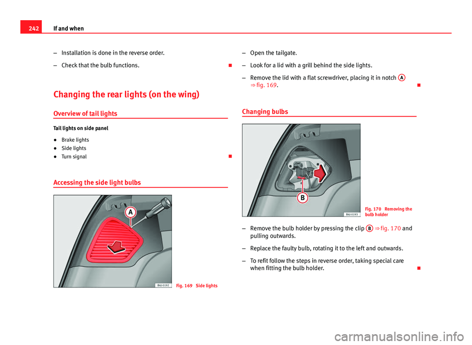
Accessing the side light bulbs
Fig. 169 Side lights –
Open the tailgate.
– Look for a lid with a grill behind the side lights.
– Remove the lid with a flat screwdriver, placing it in notch A
⇒ fig. 169.
Changing bulbs
Fig. 170 Removing the
bulb holder
– Remove the bulb holder by pressing the clip B
⇒ fig. 170 and
pulling outwards.
– Replace the faulty bulb, rotating it to the left and outwards.
– To refit follow the steps in reverse order, taking special care
when fitting the bulb holder.
Page 247 of 280

245
If and when
Interior light and front reading lights
Fig. 175 Front reading
light
To remove the glass
– Insert a fine screwdriver between the casing and the glass
⇒ fig. 175.
– Carefully remove the glass, levering it to avoid possible dam-
age.
To replace the bulbs
– Pull the bulbs outwards.
– To remove the central bulb, hold and press to one side.
Assembly
– Proceed in the reverse order, pressing gently on the outer edge
of the side light. –
First fit the glass with the fastening tabs over the frame of the
switch. Next press the front part until the two long tabs click on
the support.
Additional brake lights*
Given the difficulty involved in the replacement of this light it should be
done by the Technical Service.
Safety FirstOperating InstructionsPractical TipsTechnical Specifications
Page 250 of 280

248If and when
11. Turn on the heater blower and heated rear window in the vehi-
cle with the flat battery. This helps minimise voltage peaks
which are generated when the leads are disconnected.
12. When the engine is running, disconnect the leads in reverse order to the details given above.
Connect the battery clamps so they have good metal-to-metal contact with
the battery terminals.
If the engine fails to start, switch off the starter after about 10 seconds and
try again after about half a minute.
WARNING
● Please note the safety warnings referring to working in the engine
compartment ⇒ page 199, Working in the engine compartment.
● The battery providing assistance must have the same voltage as the
flat battery (12V) and approximately the same capacity (see imprint on
battery). Failure to comply could result in an explosion.
● Never use jump leads when one of the batteries is frozen. Danger of
explosion! Even after the battery has thawed, battery acid could leak and
cause chemical burns. If a battery freezes, it should be replaced.
● Keep sparks, flames and lighted cigarettes away from batteries, dan-
ger of explosion. Failure to comply could result in an explosion.
● Observe the instructions provided by the manufacturer of the jump
leads.
● Do not connect the negative cable from the other vehicle directly to
the negative terminal of the flat battery. The gas emitted from the battery
could be ignited by sparks. Danger of explosion.
● Do not attach the negative cable from the other vehicle to parts of the
fuel system or to the brake line.
WARNING (Continued)
● The non-insulated parts of the battery clamps must not be allowed to
touch. The jump lead attached to the positive battery terminal must not
touch metal parts of the vehicle, this can cause a short circuit.
● Position the leads in such a way that they cannot come into contact
with any moving parts in the engine compartment.
● Do not bend over the batteries. This could result in chemical burns.
Note
The vehicles must not touch each other, otherwise electricity could flow as
soon as the positive terminals are connected.