2011 Seat Ibiza SC spare wheel
[x] Cancel search: spare wheelPage 6 of 278
Accessories, parts replacement and
modifications . . . . . . . . . . . . . . . . . . . . . . . . . . . . . 183
Accessories and spare parts . . . . . . . . . . . . . . . . 183
Technical modifications . . . . . . . . . . . . . . . . . . . . 183
Roof aerial* . . . . . . . . . . . . . . . . . . . . . . . . . . . . . . 184
Mobile telephones and two-way radios . . . . . . . . 184
Fitting a towing bracket* . . . . . . . . . . . . . . . . . . . 185
Checking and refilling levels . . . . . . . . . . . . . . . 187
Refuelling . . . . . . . . . . . . . . . . . . . . . . . . . . . . . . . 187
LPG system* . . . . . . . . . . . . . . . . . . . . . . . . . . . . . 189
Petrol . . . . . . . . . . . . . . . . . . . . . . . . . . . . . . . . . . . 192
Diesel . . . . . . . . . . . . . . . . . . . . . . . . . . . . . . . . . . . 192
Working in the engine compartment . . . . . . . . . . 193
Engine oil . . . . . . . . . . . . . . . . . . . . . . . . . . . . . . . . 196
Coolant . . . . . . . . . . . . . . . . . . . . . . . . . . . . . . . . . 200
Washer fluid and windscreen wiper blades . . . . 202
Brake fluid . . . . . . . . . . . . . . . . . . . . . . . . . . . . . . . 205
Vehicle battery . . . . . . . . . . . . . . . . . . . . . . . . . . . 207
Wheels . . . . . . . . . . . . . . . . . . . . . . . . . . . . . . . . . . 209
If and when . . . . . . . . . . . . . . . . . . . . . . . . . . . . . . . 215
Vehicle tools, spare wheel . . . . . . . . . . . . . . . . . . 215
Wheel change . . . . . . . . . . . . . . . . . . . . . . . . . . . . 216
Tyre repair kit (Tyre-Mobility-System)* . . . . . . . . . 221
Fuses . . . . . . . . . . . . . . . . . . . . . . . . . . . . . . . . . . . 223
Bulb change . . . . . . . . . . . . . . . . . . . . . . . . . . . . . 226
Single headlight bulb change . . . . . . . . . . . . . . . 228
Double headlight bulb change . . . . . . . . . . . . . . . 230
Changing the bulbs of AFS headlights . . . . . . . . 234
Changing the fog light bulbs . . . . . . . . . . . . . . . . 235
Changing the rear, side and interior light bulbs . 237
Jump-starting . . . . . . . . . . . . . . . . . . . . . . . . . . . . . 240
Towing and tow-starting . . . . . . . . . . . . . . . . . . . . 243 Technical Specifications
. . . . . . . . . . . 246
Description of specifications . . . . . . . . . . . . . . . 246
Important information . . . . . . . . . . . . . . . . . . . . . 246
Information on fuel consumption . . . . . . . . . . . . 248
Towing a trailer . . . . . . . . . . . . . . . . . . . . . . . . . . . 248
Wheels . . . . . . . . . . . . . . . . . . . . . . . . . . . . . . . . . . 249
Technical specifications . . . . . . . . . . . . . . . . . . . . 250
Checking fluid levels . . . . . . . . . . . . . . . . . . . . . . . 250
Petrol engine 1.2 44 kW (60 PS) . . . . . . . . . . . . . 251
Petrol engine 1.2 51 kW (70 PS) . . . . . . . . . . . . . 252
Petrol engine/LPG 1.6 60 kW (81 PS) . . . . . . . . . 253
Petrol engine 1.4 63 kW (85 PS) . . . . . . . . . . . . . 254
Petrol engine 1.2 TSI 77 kW (105 PS) . . . . . . . . . 255
Petrol engine 1.2 TSI 77 kW (105 PS) Start-Stop 256
Petrol engine 1.6 77 kW (105 PS) . . . . . . . . . . . . 257
Petrol engine 1.4 110 kW (150 PS) . . . . . . . . . . . 258
Petrol engine 1.4 132 kW (180 PS) - Cupra . . . . . 259
Diesel engine 1.2 TDI CR 55 kW (75 PS) DPF
Start-Stop Ecomotive . . . . . . . . . . . . . . . . . . . . . . 260
Diesel engine 1.2 TDI CR 55 kW (75 PS) DPF . . . . 261
Diesel engine 1.6 TDI CR 66 kW (90 PS) DPF . . . . 262
Diesel engine 1.6 TDI CR 77 kW (105 PS) with/
without DPF . . . . . . . . . . . . . . . . . . . . . . . . . . . . . . 263
Diesel engine 2.0 TDI CR 105 kW (143 PS) DPF . 264
Dimensions and capacities . . . . . . . . . . . . . . . . . 266
Index . . . . . . . . . . . . . . . . . . . . . . . . . . . . . . . . . . . 267
4Table of Contents
Page 56 of 278
54Cockpit
Rev counter
The rev counter displays the engine speed in revolutions per
minute.
The start of the red zone ⇒ fig. 30 1
indicates the maximum engine speed
operating at service temperature. However, it is advisable to change up a in-
to a higher gear, move the selector lever to D or lift your foot off the acceler-
ator before the needle reaches the red zone.
CAUTION
The rev counter needle must never enter the red zone on the scale. Risk of
engine damage.
For the sake of the environment
Changing up into higher gears sooner, following the recommended gear in-
dications ⇒ fig. 33 will help you to reduce fuel consumption, emissions and
also engine noise.
Speedometer
The speedometer is equipped with a digital odometer and a trip recorder, in
addition to a service intervals display.
During the running-in period, the instructions shown on ⇒ page 166
should be followed. LPG system*
LPG gauge
Fig. 31 Instrument pan-
el: gas gauge.
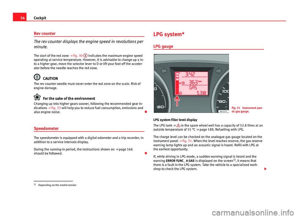
LPG system filler level display
The LPG tank ⇒
in the spare wheel well has a capacity of 52.8 litres at an
outside temperature of 15 °C ⇒ page 189, Refuelling with LPG.
The charge level can be checked on the analogue gas gauge located on the
instrument panel ⇒ fig. 31. When the level reaches reserve, the gas reserve
warning lamp lights up and an acoustic signal is heard. Refill with LPG at
the earliest opportunity.
If, while driving in LPG mode, a sudden warning signal is heard and the
warning ERROR FUNC_ A GAS is displayed on the screen 1)
, it means that
there is a fault in the LPG system. Take the vehicle to a specialised work-
shop to check the LPG system.
1)
Depending on the model version
Page 72 of 278
70Cockpit
Tyre pressure*
Fig. 40 Centre console:
tyre monitor system but-
ton
The tyre warning lamp 1)
compares wheel revolutions and with this informa-
tion, the diameter of each wheel using the ESP sensors. If the diameter of a
wheel changes, the tyre warning lamp lights up. The wheel diameter
changes when:
● Tyre pressure is insufficient.
● The tyre structure is damaged.
● The vehicle is unbalanced because of a load.
● The wheels of one axle are under more pressure (for example, driving
with a trailer or on extreme slopes).
● The vehicle is fitted with snow chains.
● The temporary spare wheel is fitted.
● The wheel on one axle is changed. Tyre pressure adjustment
Following the modification to tyre pressure or changing one or more wheels,
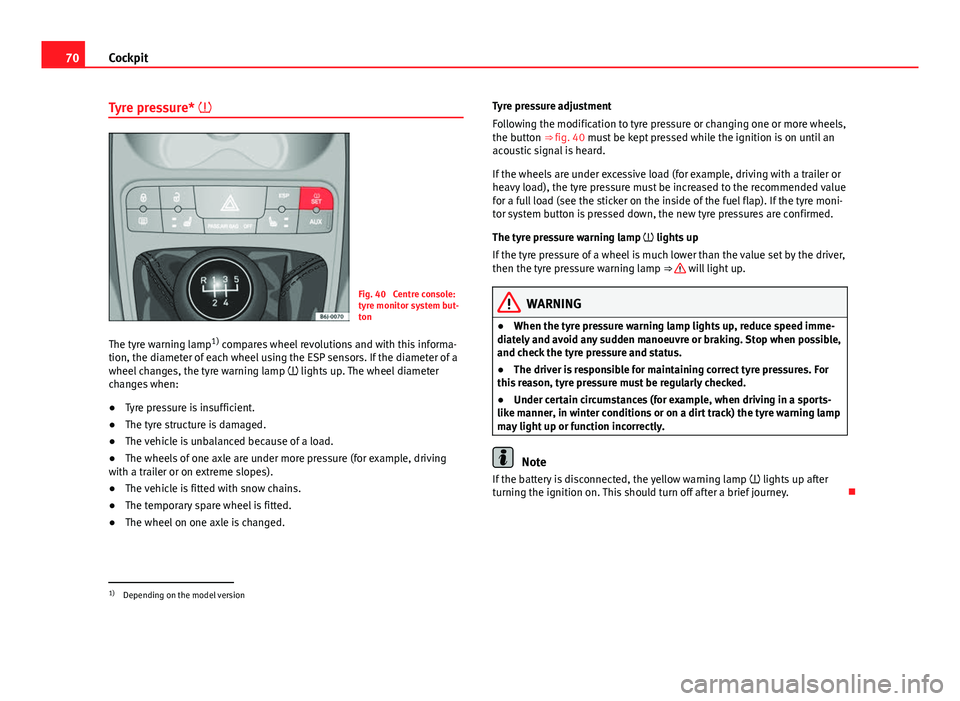
the button ⇒ fig. 40 must be kept pressed while the ignition is on until an
acoustic signal is heard.
If the wheels are under excessive load (for example, driving with a trailer or
heavy load), the tyre pressure must be increased to the recommended value
for a full load (see the sticker on the inside of the fuel flap). If the tyre moni-
tor system button is pressed down, the new tyre pressures are confirmed.
The tyre pressure warning lamp lights up
If the tyre pressure of a wheel is much lower than the value set by the driver,
then the tyre pressure warning lamp ⇒
will light up.
WARNING
● When the tyre pressure warning lamp lights up, reduce speed imme-
diately and avoid any sudden manoeuvre or braking. Stop when possible,
and check the tyre pressure and status.
● The driver is responsible for maintaining correct tyre pressures. For
this reason, tyre pressure must be regularly checked.
● Under certain circumstances (for example, when driving in a sports-
like manner, in winter conditions or on a dirt track) the tyre warning lamp
may light up or function incorrectly.
Note
If the battery is disconnected, the yellow warning lamp lights up after
turning the ignition on. This should turn off after a brief journey.
1)
Depending on the model version
Page 142 of 278
140Driving
temperature increases due to the heat accumulated in the engine compart-
ment or due to its prolonged exposure to solar radiation.
WARNING
● Never switch the engine off until the vehicle is completely stationary.
● The brake servo works only when the engine is running. With the en-
gine switched off, more strength is needed to brake. As normal brake op-
eration cannot be performed, risk of accidents and serious injury may ex-
ist.
● The steering lock can be immediately blocked once the key is re-
moved from the ignition. The vehicle cannot be steered. Risk of accident.
CAUTION
When the engine has been running under a heavy load for a long period,
heat can accumulate in the engine compartment and cause engine damage.
For this reason, you should idle the engine for approx. 2 minutes before you
switch it off. Driving with LPG*Fig. 99 Centre console:
gas system control
switch.
Your SEAT vehicle has a bivalent engine able to run on either LPG or petrol.
The LPG tank ⇒ page 189, Refuelling with LPG is in the spare wheel well
⇒
.
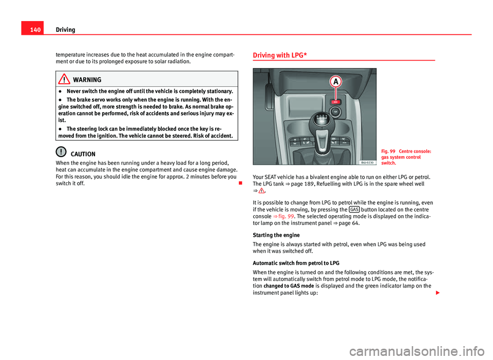
It is possible to change from LPG to petrol while the engine is running, even
if the vehicle is moving, by pressing the GAS
button located on the centre
console ⇒ fig. 99. The selected operating mode is displayed on the indica-
tor lamp on the instrument panel ⇒ page 64.
Starting the engine
The engine is always started with petrol, even when LPG was being used
when it was switched off.
Automatic switch from petrol to LPG
When the engine is turned on and the following conditions are met, the sys-
tem will automatically switch from petrol mode to LPG mode, the notifica-
tion changed to GAS mode is displayed and the green indicator lamp on the
instrument panel lights up:
Page 165 of 278

163
Intelligent technology
TCS helps the vehicle to start moving, accelerate and climb a gradient in
slippery conditions where this may otherwise be difficult or even impossi-
ble.
The TCS is switched on automatically when the engine is started. If necessa-
ry, it may be turned on or off by briefly pushing the ESP button on the centre
console.
When the TCS is off, the warning lamp is lit. The TCS should normally be
left on. Only in exceptional circumstances, when the slipping of the wheels
is required, can they be disconnected using the ESP button, for example.
● With compact temporary spare wheel.
● When using the snow chains.
● When driving in deep snow or on loose surfaces
● When the vehicle is bogged-down, to free it by rocking.
The TCS should be switched on again as soon as possible.
WARNING
● It must be remembered that TCS cannot defy the laws of physics. This
should be kept in mind, particularly on slippery and wet roads and when
towing a trailer.
● Always adapt your driving style to suit the condition of the roads and
the traffic situation. Do not let the extra safety afforded by TCS tempt you
into taking any risks when driving, this can cause accidents.
CAUTION
● In order to ensure that TCS function correctly, all four wheels must be fit-
ted with the same tyres. Any differences in the rolling radius of the tyres can
cause the system to reduce engine power when this is not desired.
● Modifications to the vehicle (e.g. to the engine, the brake system, run-
ning gear or any components affecting the wheels and tyres) could affect
the efficiency of the ABS and TCS. XDS*
Driveshaft differential
When taking a bend, the driveshaft differential mechanism allows the outer
wheel to turn at a higher speed than the inner wheel. In this way, the wheel
that is turning faster (outer wheel) receives less drive torque than the inner
wheel. This may mean that in certain situations the torque delivered to the
inner wheel is too high, causing the wheels to spin. On the other hand, the
outer wheel is receiving a lower drive torque than it could transmit. This
causes an overall loss of lateral grip on the front axle, resulting in under-
steer or “lengthening” of the trajectory.
By using the ESP sensors and signals, the XDS system is able to detect and
correct this effect.
Through the ESP, the XDS brakes the inner wheel, thereby counteracting the
excess drive torque in this wheel. This means that the driver's desired tra-
jectory is much more precise,
The XDS system operates in combination with the ESP and is always active,
even when the traction control, TCS, is disconnected.
Electronic Stability Programme (ESP)* General notes
The Electronic Stability Programme increases the vehicle's
stability on the road.
The Electronic Stability Programme helps reduce the danger of skidding.
The Electronic Stability Programme (ESP) consists of ABS, EDL and TCS.
Safety FirstOperating InstructionsPractical TipsTechnical Specifications
Page 191 of 278

189
Checking and refilling levels
LPG system*
Refuelling with LPG
The LPG filler neck is behind the fuel cap, next to the petrol
filler neck.
Fig. 119 Fuel tank open with LPG filler neck and adapter.
Fig. 120 LPG tank in
spare wheel well
Refuelling with LPG
– Before refuelling, stop the engine and switch off the ignition.
– Open the tank flap.
– Before refuelling, please read the instructions on the pump.
– Unscrew the cap of the gas filler neck ⇒ fig. 119 1
.
– Screw the required adapter ⇒ fig. 119 2
on the gas filler neck
1.
– Refuel as indicated in the instructions on the pump.
– Unscrew the adapter ⇒ fig. 119 2
.
– Screw on the cap of the gas filler neck ⇒ fig. 119 1
.
– Close the tank flap.
When the hose is removed from the tank, a small amount of LPG may spill
out ⇒
.
Safety FirstOperating InstructionsPractical TipsTechnical Specifications
Page 192 of 278
190Checking and refilling levels
The LPG tank ⇒ fig. 120 in the spare wheel well has a capacity of 52.8 litres.
If the outside temperatures are very low, it may not be possible to complete-
ly fill the LPG tank.
Pump attachments
There are a variety of types of LPG pump, and the methods of use may vary.
Therefore, let the pump operator fill the tank when refuelling for the first
time or fill from another pump.
Noises when refuelling with LPG
When refuelling with LPG, noises may be heard. These noises are insignifi-
cant.
WARNING
Failure to refuel or handle LPG in the correct way could result in a fire,
cause an explosion or lead to injuries.
● LPG is a highly explosive and inflammable substance. It may cause
severe burns and other injury.
● Switch off the engine before refuelling.
● Always disconnect mobile phones and any other radiophony applian-
ces, as electromagnetic waves may produce sparks and cause a fire.
● Do not remain in the vehicle while refuelling. If it is absolutely neces-
sary to enter the vehicle, close the door and touch a metal surface before
touching the attachment again. This will prevent the generation of static
electricity and any possible fires while refuelling.
● Small quantities of LPG may leak out after refuelling. If LPG comes in-
to contact with skin, there is a risk of freezing.
● Do not smoke and always keep bare flames away from the tank during
refuelling. Failure to do so may lead to an explosion.
Adapter for the liquid petroleum gas (LPG) filler neck
An adapter is required due to the existence of a range of
pumps with different nozzles.
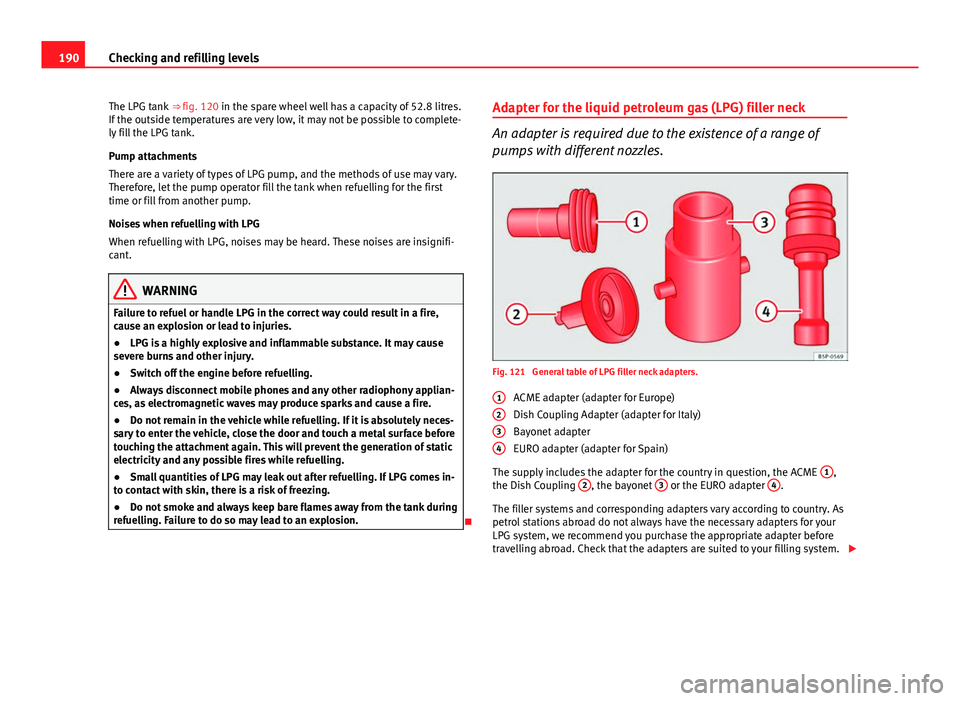
Fig. 121 General table of LPG filler neck adapters.
ACME adapter (adapter for Europe)
Dish Coupling Adapter (adapter for Italy)
Bayonet adapter
EURO adapter (adapter for Spain)
The supply includes the adapter for the country in question, the ACME 1
,
the Dish Coupling 2, the bayonet 3 or the EURO adapter 4.
The filler systems and corresponding adapters vary according to country. As
petrol stations abroad do not always have the necessary adapters for your
LPG system, we recommend you purchase the appropriate adapter before
travelling abroad. Check that the adapters are suited to your filling system.
1
234
Page 210 of 278
208Checking and refilling levels
CAUTION
● Never disconnect the battery if the ignition is switched on or if the en-
gine is running. This could damage the electrical system or electronic com-
ponents.
● Do not expose the battery to direct sunlight over a long period of time,
as the intense ultraviolet radiation can damage the battery housing.
● If the vehicle is left standing in cold conditions for a long period, protect
the battery from freezing. If it freezes it will be damaged.
Checking the electrolyte level
The electrolyte level should be checked regularly in high-
mileage vehicles, in hot countries and in older batteries. – Open the engine bonnet and the battery cover ⇒
in Safety in-
structions on working in the engine compartment on page 194
⇒
in Warnings on handling the battery on page 207. For vehi-
cles with the battery under the spare wheel, open the tailgate
and lift the floor covering. The battery is located next to the
spare wheel.
– Check the colour display in the "magic eye" on the top of the
battery.
– If there are air bubbles in the window, tap the window gently
until they disperse.
The position of the battery is shown in the corresponding engine compart-
ment diagram ⇒ page 250. The location of the battery in the luggage com-
partment can be seen in ⇒ fig. 175.
The “magic eye” indicator, located on the top of the battery changes colour,
depending on the charge state and electrolyte level of the battery. There are two different colours:
●
Black: correct charge status.
● Transparent/clear yellow: the battery must be replaced. Contact a spe-
cialist workshop.
Charging and changing the vehicle battery
The battery is maintenance-free and is checked during the
inspection service. All work on the vehicle battery requires
specialist knowledge.
If you often drive short distances or if the vehicle is not driven for long peri-
ods, the battery should be checked by a specialised workshop between the
scheduled services.
If the battery has discharged and you have problems starting the vehicle,
the battery might be damaged. If this happens, we recommend you have
the vehicle battery checked by an Authorised Service Centre where it will be
re-charged or replaced.
Charging the battery
The vehicle battery should be charged by a specialised workshop only, as
batteries using special technology have been installed and they must be
charged in a controlled environment.
Replacing a vehicle battery
The battery has been developed to suit the conditions of its location and
has special safety features.
Genuine SEAT batteries fulfil the maintenance, performance and safety
specifications of your vehicle.