Page 205 of 278

203
Checking and refilling levels
Changing windscreen wiper blades
If the windscreen wiper blades are in perfect condition, you
will benefit from an improved visibility. Damaged wiper
blades should be replaced immediately.
Fig. 128 Windscreen
wipers in service position
Fig. 129 Change wind-
screen wiper blade To change the blades it is necessary to change the rest position of
the wipers to the service position.
Do not change the windscreen wipers when out of the service posi-
tion, as it could cause paint to flake off the bonnet due to friction
with the windscreen wiper arm.
Service position (For changing wiper blades)
–
Ensure that the wiper blades are not frozen.
– Turn ignition on and off and then (before approx. 9 sec.) move
the windscreen wiper lever to the intermittent wipe position.
The windscreen wipers will move to the service position
⇒ fig. 128.
Removing the wiper blade
– Lift the windscreen wiper arm.
– Press on the securing tab ⇒ fig. 129.
– Extract the wiper blade from the wiper arm.
Fitting the wiper blade
– Insert the wiper blade onto the windscreen wiper arm until it
clicks into place.
– Place the wiper arms to their initial position.
If the windscreen wipers smear , they should be replaced if they are dam-
aged, or cleaned if they are soiled.
If this does not produce the desired results, the setting angle of the wind-
screen wiper arms might be incorrect. They should be checked by a special-
ised workshop and corrected if necessary.
Safety FirstOperating InstructionsPractical TipsTechnical Specifications
Page 206 of 278

204Checking and refilling levels
WARNING
Do not drive unless you have good visibility through all windows!
● Clean the windscreen wiper blades and all windows regularly.
● The wiper blades should be changed once or twice a year.
CAUTION
● Damaged or dirty windscreen wipers could scratch the windscreen.
● Never use fuel, nail varnish remover, paint thinner or similar products to
clean the windows. This could damage the windscreen wiper blades.
● Never move the windscreen wiper or windscreen wiper arm manually.
This could cause damage.
● To avoid damage to the bonnet and the windscreen wiper arms, the lat-
ter should only be lifted off the windscreen when in service position.
Note
● The wiper arms can be moved to the service position only when the bon-
net is properly closed.
● You can also use the service position, for example, if you want to fix a
cover over the windscreen in the winter to keep it clear of ice. Changing the rear wiper blade
A good rear wiper blade is essential for clear rear vision.
Damaged wiper blades should be replaced immediately.
Fig. 130 Removing the
rear window wiper blade
Fig. 131 Fitting the rear
window wiper blade
Page 208 of 278
206Checking and refilling levels
WARNING
Before opening the bonnet to check the brake fluid level, read and ob-
serve the warnings ⇒ page 193.
Changing the brake fluid
The Maintenance Programme indicates the brake fluid
change intervals. We recommend that you have the brake fluid changed by an Authorised
Service Centre.
Before opening the bonnet, please read and follow the warnings ⇒
in
Safety instructions on working in the engine compartment on page 193 in
section “Safety notes for working in the engine compartment”.
Brake fluid absorbs moisture. In the course of time, it will absorb water from
the ambient air. If the water content in the brake fluid is too high, the brake
system could corrode. This also considerably reduces the boiling point of
the brake fluid. Heavy use of the brakes may then cause a vapour lock
which could impair the braking effect.
It is important that you use only brake fluid compliant with US standard
FMVSS 116 DOT 4. We recommend the use of Genuine SEAT brake fluid.
WARNING
Brake fluid is poisonous. Old brake fluid impairs the braking effect.
● Before opening the bonnet to check the brake fluid level, read and ob-
serve the warnings ⇒ page 193.
WARNING (Continued)
● Brake fluid should be stored in the closed original container in a safe
place out of reach of children. There is a toxic risk.
● Complete the brake fluid change according to the Maintenance Pro-
gramme. Heavy use of the brakes may cause a vapour lock if the brake
fluid is left in the system for too long. This would seriously affect the effi-
ciency of the brakes and the safety of the vehicle. This may cause an ac-
cident.
CAUTION
Brake fluid could damage the paintwork. Wipe off any brake fluid from the
paintwork immediately.
For the sake of the environment
The brake pads and fluid must be collected and disposed of according the
applicable regulations. The SEAT Technical Service network has the neces-
sary equipment and qualified personnel for collecting and disposing of this
waste material.
Page 210 of 278
208Checking and refilling levels
CAUTION
● Never disconnect the battery if the ignition is switched on or if the en-
gine is running. This could damage the electrical system or electronic com-
ponents.
● Do not expose the battery to direct sunlight over a long period of time,
as the intense ultraviolet radiation can damage the battery housing.
● If the vehicle is left standing in cold conditions for a long period, protect
the battery from freezing. If it freezes it will be damaged.
Checking the electrolyte level
The electrolyte level should be checked regularly in high-
mileage vehicles, in hot countries and in older batteries. – Open the engine bonnet and the battery cover ⇒
in Safety in-
structions on working in the engine compartment on page 194
⇒
in Warnings on handling the battery on page 207. For vehi-
cles with the battery under the spare wheel, open the tailgate
and lift the floor covering. The battery is located next to the
spare wheel.
– Check the colour display in the "magic eye" on the top of the
battery.
– If there are air bubbles in the window, tap the window gently
until they disperse.
The position of the battery is shown in the corresponding engine compart-
ment diagram ⇒ page 250. The location of the battery in the luggage com-
partment can be seen in ⇒ fig. 175.
The “magic eye” indicator, located on the top of the battery changes colour,
depending on the charge state and electrolyte level of the battery. There are two different colours:
●
Black: correct charge status.
● Transparent/clear yellow: the battery must be replaced. Contact a spe-
cialist workshop.
Charging and changing the vehicle battery
The battery is maintenance-free and is checked during the
inspection service. All work on the vehicle battery requires
specialist knowledge.
If you often drive short distances or if the vehicle is not driven for long peri-
ods, the battery should be checked by a specialised workshop between the
scheduled services.
If the battery has discharged and you have problems starting the vehicle,
the battery might be damaged. If this happens, we recommend you have
the vehicle battery checked by an Authorised Service Centre where it will be
re-charged or replaced.
Charging the battery
The vehicle battery should be charged by a specialised workshop only, as
batteries using special technology have been installed and they must be
charged in a controlled environment.
Replacing a vehicle battery
The battery has been developed to suit the conditions of its location and
has special safety features.
Genuine SEAT batteries fulfil the maintenance, performance and safety
specifications of your vehicle.
Page 230 of 278
228If and when
Single headlight bulb change
Single headlight bulb
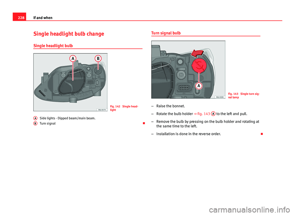
Fig. 142 Single head-
light
Side lights - Dipped beam/main beam.
Turn signal
A
B
Turn signal bulb
Fig. 143 Single turn sig-
nal lamp
– Raise the bonnet.
– Rotate the bulb holder ⇒ fig. 143 A
to the left and pull.
– Remove the bulb by pressing on the bulb holder and rotating at
the same time to the left.
– Installation is done in the reverse order.
Page 231 of 278
229
If and when
Dipped/main beam headlights
Fig. 144 Dipped beam/
main beam, single head-
light
Fig. 145 Dipped beam/
main beam, single head-
light
– Raise the bonnet.
– Move the loop ⇒ fig. 144 1
in the direction of the arrow and
remove the cover. –
Remove the connector ⇒ fig. 145 2
from the bulb.
– Unclip the retainer spring ⇒ fig. 145 3
pressing inwards to the
right.
– Extract the bulb and fit the replacement so that the rim of the
attachment plate is on the reflector cut-out.
– Fit the connector.
– Fit the cover and close the strap. Make sure that the gasket sits
well on the casing cover during the operation.
– Check whether the new bulb is working.
Side light
Fig. 146 Side lights
– Raise the bonnet.
Safety FirstOperating InstructionsPractical TipsTechnical Specifications
Page 233 of 278

231
If and when
– Raise the bonnet.
– Move the loop 1
in the direction of the arrow and remove the
cover ⇒ fig. 148.
– Remove connector ⇒ fig. 149 2
by pulling outward.
– Remove the bulb by pulling it out and fitting the new one.
– Installation is done in the reverse order.
– Fit the cover and close the strap. Make sure that the gasket sits
well on the casing cover during the operation.
– Check whether the new bulb is working.
Main beam headlights
Fig. 150 Main beam
headlights
Fig. 151 Main beam
headlights
– Raise the bonnet.
– Move the loop 1
in the direction of the arrow and remove the
cover ⇒ fig. 150.
– Remove connector ⇒ fig. 151 2
by pulling outward.
– Extract the bulb and fit the replacement so that it sits correctly
into the cut-out on the reflector.
– Installation is done in the reverse order.
– Fit the cover and close the strap. Make sure that the gasket sits
well on the casing cover during the operation.
– Check whether the new bulb is working.
Safety FirstOperating InstructionsPractical TipsTechnical Specifications
Page 234 of 278
232If and when
Dipped beam headlights
Fig. 152 Dipped beam
headlights
Fig. 153 Dipped beam
headlights
– Raise the bonnet.
– Move the loop ⇒ fig. 152 1
in the direction of the arrow and
remove the cover. –
Remove the connector ⇒ fig. 153 2
from the bulb.
– Unclip the retainer spring ⇒ fig. 153 3
pressing inwards to the
right.
– Extract the bulb and fit the replacement so that the rim of the
attachment plate is on the reflector cut-out.
– Fit the connector.
– Fit the cover and close the strap. Make sure that the gasket sits
well on the casing cover during the operation.
– Check whether the new bulb is working.
Turn signal lights
Fig. 154 Turn signal
– Raise the bonnet.