2011 Seat Ibiza SC engine coolant
[x] Cancel search: engine coolantPage 6 of 278

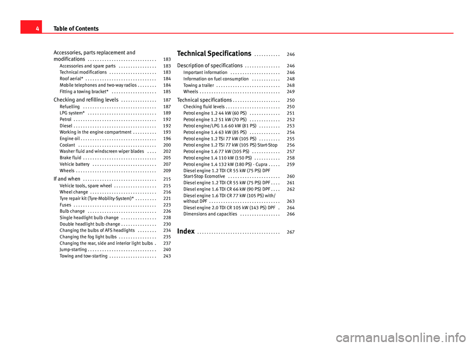
Accessories, parts replacement and
modifications . . . . . . . . . . . . . . . . . . . . . . . . . . . . . 183
Accessories and spare parts . . . . . . . . . . . . . . . . 183
Technical modifications . . . . . . . . . . . . . . . . . . . . 183
Roof aerial* . . . . . . . . . . . . . . . . . . . . . . . . . . . . . . 184
Mobile telephones and two-way radios . . . . . . . . 184
Fitting a towing bracket* . . . . . . . . . . . . . . . . . . . 185
Checking and refilling levels . . . . . . . . . . . . . . . 187
Refuelling . . . . . . . . . . . . . . . . . . . . . . . . . . . . . . . 187
LPG system* . . . . . . . . . . . . . . . . . . . . . . . . . . . . . 189
Petrol . . . . . . . . . . . . . . . . . . . . . . . . . . . . . . . . . . . 192
Diesel . . . . . . . . . . . . . . . . . . . . . . . . . . . . . . . . . . . 192
Working in the engine compartment . . . . . . . . . . 193
Engine oil . . . . . . . . . . . . . . . . . . . . . . . . . . . . . . . . 196
Coolant . . . . . . . . . . . . . . . . . . . . . . . . . . . . . . . . . 200
Washer fluid and windscreen wiper blades . . . . 202
Brake fluid . . . . . . . . . . . . . . . . . . . . . . . . . . . . . . . 205
Vehicle battery . . . . . . . . . . . . . . . . . . . . . . . . . . . 207
Wheels . . . . . . . . . . . . . . . . . . . . . . . . . . . . . . . . . . 209
If and when . . . . . . . . . . . . . . . . . . . . . . . . . . . . . . . 215
Vehicle tools, spare wheel . . . . . . . . . . . . . . . . . . 215
Wheel change . . . . . . . . . . . . . . . . . . . . . . . . . . . . 216
Tyre repair kit (Tyre-Mobility-System)* . . . . . . . . . 221
Fuses . . . . . . . . . . . . . . . . . . . . . . . . . . . . . . . . . . . 223
Bulb change . . . . . . . . . . . . . . . . . . . . . . . . . . . . . 226
Single headlight bulb change . . . . . . . . . . . . . . . 228
Double headlight bulb change . . . . . . . . . . . . . . . 230
Changing the bulbs of AFS headlights . . . . . . . . 234
Changing the fog light bulbs . . . . . . . . . . . . . . . . 235
Changing the rear, side and interior light bulbs . 237
Jump-starting . . . . . . . . . . . . . . . . . . . . . . . . . . . . . 240
Towing and tow-starting . . . . . . . . . . . . . . . . . . . . 243 Technical Specifications
. . . . . . . . . . . 246
Description of specifications . . . . . . . . . . . . . . . 246
Important information . . . . . . . . . . . . . . . . . . . . . 246
Information on fuel consumption . . . . . . . . . . . . 248
Towing a trailer . . . . . . . . . . . . . . . . . . . . . . . . . . . 248
Wheels . . . . . . . . . . . . . . . . . . . . . . . . . . . . . . . . . . 249
Technical specifications . . . . . . . . . . . . . . . . . . . . 250
Checking fluid levels . . . . . . . . . . . . . . . . . . . . . . . 250
Petrol engine 1.2 44 kW (60 PS) . . . . . . . . . . . . . 251
Petrol engine 1.2 51 kW (70 PS) . . . . . . . . . . . . . 252
Petrol engine/LPG 1.6 60 kW (81 PS) . . . . . . . . . 253
Petrol engine 1.4 63 kW (85 PS) . . . . . . . . . . . . . 254
Petrol engine 1.2 TSI 77 kW (105 PS) . . . . . . . . . 255
Petrol engine 1.2 TSI 77 kW (105 PS) Start-Stop 256
Petrol engine 1.6 77 kW (105 PS) . . . . . . . . . . . . 257
Petrol engine 1.4 110 kW (150 PS) . . . . . . . . . . . 258
Petrol engine 1.4 132 kW (180 PS) - Cupra . . . . . 259
Diesel engine 1.2 TDI CR 55 kW (75 PS) DPF
Start-Stop Ecomotive . . . . . . . . . . . . . . . . . . . . . . 260
Diesel engine 1.2 TDI CR 55 kW (75 PS) DPF . . . . 261
Diesel engine 1.6 TDI CR 66 kW (90 PS) DPF . . . . 262
Diesel engine 1.6 TDI CR 77 kW (105 PS) with/
without DPF . . . . . . . . . . . . . . . . . . . . . . . . . . . . . . 263
Diesel engine 2.0 TDI CR 105 kW (143 PS) DPF . 264
Dimensions and capacities . . . . . . . . . . . . . . . . . 266
Index . . . . . . . . . . . . . . . . . . . . . . . . . . . . . . . . . . . 267
4Table of Contents
Page 64 of 278

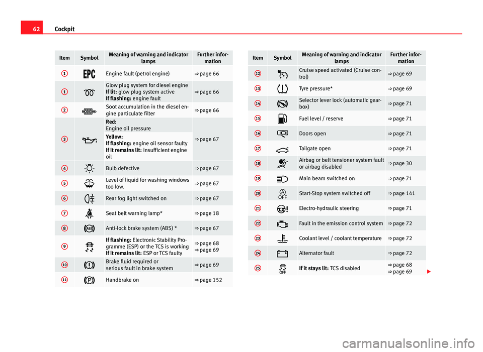
62Cockpit
ItemSymbolMeaning of warning and indicator
lampsFurther infor-mation
1Engine fault (petrol engine)⇒ page 66
1Glow plug system for diesel engine
If lit: glow plug system active
If flashing: engine fault⇒ page 66
2Soot accumulation in the diesel en-
gine particulate filter⇒ page 66
3
Red:
Engine oil pressure
⇒ page 67Yellow:
If flashing: engine oil sensor faulty
If it remains lit: insufficient engine
oil
4Bulb defective⇒ page 67
5Level of liquid for washing windows
too low.⇒ page 67
6Rear fog light switched on⇒ page 67
7Seat belt warning lamp*⇒ page 18
8Anti-lock brake system (ABS) *⇒ page 67
9
If flashing: Electronic Stability Pro-
gramme (ESP) or the TCS is working
If it remains lit: ESP or TCS faulty⇒ page 68
⇒ page 69
10Brake fluid required or
serious fault in brake system⇒ page 69
11Handbrake on⇒ page 152
ItemSymbolMeaning of warning and indicator
lampsFurther infor-mation
12Cruise speed activated (Cruise con-
trol)⇒ page 69
13Tyre pressure*⇒ page 69
14Selector lever lock (automatic gear-
box)⇒ page 71
15Fuel level / reserve⇒ page 71
16Doors open⇒ page 71
17Tailgate open⇒ page 71
18Airbag or belt tensioner system fault
or airbag disabled⇒ page 30
19Main beam switched on⇒ page 71
20Start-Stop system switched off⇒ page 141
21Electro-hydraulic steering⇒ page 71
22Fault in the emission control system⇒ page 72
23Coolant level / coolant temperature⇒ page 72
24Alternator fault⇒ page 72
25If it stays lit: TCS disabled⇒ page 68
⇒ page 69
Page 67 of 278

65
Cockpit
If several priority 1 faults are detected at the same time, the symbols will be
displayed one after the other for about 2 seconds at a time and will contin-
ue until the fault is corrected.
No menus will be shown in the display for the duration of a priority 1 warn-
ing message.
Examples of priority 1 warning messages (red)
● Brake system symbol with the warning message STOP BRAKE FLUID
SERVICE MANUAL or STOP BRAKE FAULT SERVICE MANUAL .
● Coolant symbol with the warning message STOP SEE COOLANT IN-
STRUCTION MANUAL.
● Engine oil pressure symbol with the warning message STOP ENGINE
OIL PRESSURE LOW! INSTRUCTION MANUAL .
Warning reports, Priority 2 (yellow)
If one of these faults occurs, the warning lamp lights up, and is accompa-
nied by one audible warning. Check the corresponding function as soon as
possible although the vehicle may be used without risk.
If several priority 2 warning messages are detected at the same time, the
symbols are displayed one after the other for about 2 seconds at a time. Af-
ter a set time, the information text will disappear and the symbol will be
shown as a reminder at the side of the display.
Priority 2 warning messages will not be shown until all Priority 1 warning
messages have been dealt with!
Examples of priority 2 warning messages (yellow): 1)
● Fuel warning light with the information text PLEASE REFUEL. Information messages displayed on the screen*
Message
a)Description
SERVICEThe service interval has ended. Take the vehicle to an au-
thorised service.
IMMOBILIS-
ERImmobiliser system active. The vehicle will not start. Take
the vehicle to an authorised service.
ERRORInstrument panel faulty. Take the vehicle to an authorised
service.
CLEAN AIRFILTERWarning: Clean the air filter.
NO KEYWarning: Correct key cannot be found in the vehicle.KEY BATTERYWarning: Key battery low. Change the battery.
CLUTCHWarning: Press the clutch to start. In vehicles with manual
gearbox and Start/Stop system.
--> P/NWarning: Place the selector level in P/N to start. Only in ve-
hicles with automatic gearbox.
--> PWarning: Place the selector lever in position P to stop the
engine.
STARTINGWarning: The engine starts automatically. Start-Stop system
activated.
START MAN- UALLYWarning: The engine must be started manually. Start-Stop
system activated.
ERROR
START STOPWarning: Start-Stop system error.
START STOP
IMPOSSIBLEWarning: Although the Start-Stop system is switched on, the
engine cannot be stopped automatically. Not all the neces-
sary conditions are met.
START STOP ACTIVEWarning: Start-Stop system activated. Vehicle in Stop mode.
1)
Depending on the version of the model.
Safety FirstOperating InstructionsPractical TipsTechnical Specifications
Page 74 of 278

72Cockpit
Emission control system*
This warning lamp monitors the exhaust system.
Warning lamp flashes:
When there is misfiring that can damage the catalytic converter. Reduce
speed and drive carefully to the nearest specialised workshop to have the
engine checked.
Warning lamp is lit:
If a fault has developed during driving which has reduced the quality of the
exhaust gas (e.g. lambda probe fault). Reduce speed and drive carefully to
the nearest specialised workshop to have the engine checked.
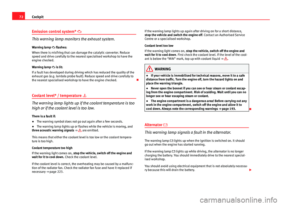
Coolant level* / temperature
The warning lamp lights up if the coolant temperature is too
high or if the coolant level is too low.
There is a fault if:
● The warning symbol does not go out again after a few seconds.
● The warning lamp lights up or flashes while the vehicle is moving, and
three acoustic warning signals ⇒
are emitted.
This means that either the coolant level is too low or the coolant tempera-
ture is too high.
Coolant temperature too high
If the warning light comes on, stop the vehicle, switch off the engine and
wait for it to cool down. Check the coolant level.
If the coolant level is correct, the overheating may be caused by a malfunc-
tion of the radiator fan. Check the radiator fan fuse and have it replaced if
necessary ⇒ page 223. If the warning lamp lights up again after driving on for a short distance,
stop the vehicle and switch the engine off
. Contact an Authorised Service
Centre or a specialised workshop.
Coolant level too low
If the warning light comes on, stop the vehicle, switch off the engine and
wait for it to cool down . First check the coolant level. If the level of the cool-
ant is below the “MIN” mark, top up with coolant liquid ⇒
.
WARNING
● If your vehicle is immobilised for technical reasons, move it to a safe
distance from traffic. Turn the engine off, turn the hazard lights on and
place the warning triangle.
● Never open the bonnet if you can see or hear steam or coolant escap-
ing from the engine compartment. Risk of scalding. Wait until you can no
longer see or hear escaping steam or coolant.
● The engine compartment is a dangerous area! Before carrying out any
work in the engine compartment, switch off the engine and allow it to
cool down. Always note the corresponding warnings ⇒ page 193.
Alternator
This warning lamp signals a fault in the alternator.
The warning lamp lights up when the ignition is switched on. It should
go out when the engine has started running.
If the warning lamp lights up while driving, the alternator is no longer
charging the battery. You should immediately drive to the nearest special-
ised workshop.
You should avoid using electrical equipment that is not absolutely necessa-
ry because this will drain the battery.
Page 129 of 278

127
Air conditioning
– Turn blower switch B
to any of the head settings 2 -3.
– Turn air distribution control to .
– Close outlets 3
–
Open and turn outlets 4 towards side windows
Once the windows are demisted and as a preventive measure, the control C
can be set in position , thus obtaining greater comfort while prevent-
ing the windows from misting again. Heating
Maximum heat output, which is needed to defrost the windows quickly, is
only available when the engine has reached its operating temperature.
Note
Remember that the temperature of the engine coolant should be optimum
to ensure that the heating system functions correctly (except in vehicles fit-
ted with additional heating*)
Air outlets
Fig. 92 Air vents
Safety FirstOperating InstructionsPractical TipsTechnical Specifications
Page 131 of 278

129
Air conditioning
WARNING
For your safety, the windows should never be fogged up or covered with
snow or ice. This is essential to ensure good visibility. Please familiarise
yourself with the correct operation of the heating and ventilation system,
including the demist/defrost functions for the windows.
Note
Please consider the general notes.
Vehicle interior heating or cooling system
Fig. 94 Air conditioning
controls on the dash pan-
el
Interior heating
– Disconnect the cooling system using button ⇒ fig. 94 AC
(the
button light turns off). –
Turn the temperature selector A
to set the desired temperature
inside the vehicle.
– Turn the blower switch to any of the settings 1-4.
– Set the air distribution control C
to the air flow configuration
desired: (towards the windscreen), (towards the chest),
(towards the footwell) and (towards the windscreen and
footwell areas).
Interior cooling
– Connect the cooling system with button AC
(the button light
should light up).
– Turn the temperature control switch until the desired interior
temperature is reached.
– Turn the blower switch to any of the settings 1-4.
– Set the air distribution control to the air flow configuration de-
sired:
(towards the windscreen), (towards the chest), (towards the footwell) and (towards the windscreen and
footwell areas).
Heating
Maximum heat output, which is needed to defrost the windows quickly, is
only available when the engine has reached its operating temperature.
Coolant system
When the air conditioning is switched on, the temperature and the air hu-
midity go down. This way, if the outside humidity is extreme, the air condi-
tioning prevents the misting of the windows and therefore, comfort is im-
proved.
If the air conditioning does not work, this may be due to the following rea-
sons:
Safety FirstOperating InstructionsPractical TipsTechnical Specifications
Page 132 of 278

130Air conditioning
● The engine is stationary.
● The fan blower is switched off.
● The outside temperature is below +3 ℃.
● The cooling system compressor has been temporarily switched off be-
cause of an increased engine coolant temperature.
● The air conditioner fuse is faulty.
● Another fault in the vehicle. Have the air conditioning checked by a
qualified workshop.
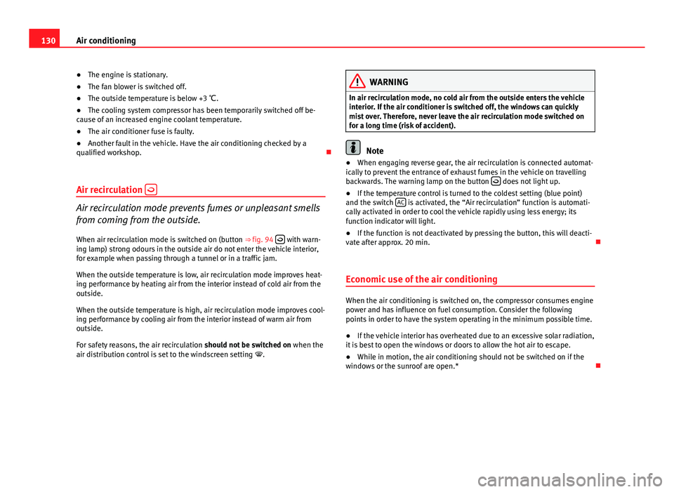
Air recirculation
Air recirculation mode prevents fumes or unpleasant smells
from coming from the outside.
When air recirculation mode is switched on (button ⇒ fig. 94
with warn-
ing lamp) strong odours in the outside air do not enter the vehicle interior,
for example when passing through a tunnel or in a traffic jam.
When the outside temperature is low, air recirculation mode improves heat-
ing performance by heating air from the interior instead of cold air from the
outside.
When the outside temperature is high, air recirculation mode improves cool-
ing performance by cooling air from the interior instead of warm air from
outside.
For safety reasons, the air recirculation should not be switched on when the
air distribution control is set to the windscreen setting .
WARNING
In air recirculation mode, no cold air from the outside enters the vehicle
interior. If the air conditioner is switched off, the windows can quickly
mist over. Therefore, never leave the air recirculation mode switched on
for a long time (risk of accident).
Note
● When engaging reverse gear, the air recirculation is connected automat-
ically to prevent the entrance of exhaust fumes in the vehicle on travelling
backwards. The warning lamp on the button
does not light up.
● If the temperature control is turned to the coldest setting (blue point)
and the switch AC
is activated, the “Air recirculation” function is automati-
cally activated in order to cool the vehicle rapidly using less energy; its
function indicator will light.
● If the function is not deactivated by pressing the button, this will deacti-
vate after approx. 20 min.
Economic use of the air conditioning
When the air conditioning is switched on, the compressor consumes engine
power and has influence on fuel consumption. Consider the following
points in order to have the system operating in the minimum possible time.
● If the vehicle interior has overheated due to an excessive solar radiation,
it is best to open the windows or doors to allow the hot air to escape.
● While in motion, the air conditioning should not be switched on if the
windows or the sunroof are open.*
Page 141 of 278

139
Driving
Starting diesel engines
The engine can only be started using a genuine SEAT key
with its correct code. – Move the gear lever to the neutral position and depress the
clutch pedal thoroughly and hold it in this position for the start-
er to turn the engine on.
– Turn the ignition key to the starting position.
– Turn the ignition key to position ⇒ fig. 98 2
. The indicator
lamp will light for engine pre-heating.
– When the warning lamp turns off, turn the key to position 3
to
start the engine. Do not press the accelerator.
– Let go of the ignition key as soon as the engine starts, the start-
er motor must not be allowed to run on with the engine.
When starting a very cold engine, it may be a little noisy for the first few sec-
onds until oil pressure has built up in the hydraulic valve compensators.
This is quite normal, and no cause for concern.
If there are problems starting the engine, see the ⇒ page 240.
Glow plug system for the diesel engine
To avoid unnecessary discharging of the battery, do not use any other major
electrical equipment while the glow plugs are pre-heating.
Start the engine as soon as the glow plug warning lamp goes out.
Starting the engine after the fuel tank has been completely run dry
If the fuel tank has been completely run dry, it may take longer than normal
(up to one minute) to start the engine after refuelling with diesel fuel. This is
because the system must eliminate air first.
WARNING
● Never start or run the engine in unventilated or closed rooms. The ex-
haust fumes contain carbon monoxide, an odourless and colourless poi-
sonous gas. Risk of fatal accidents. Carbon monoxide can cause loss of
consciousness. It can also cause death.
● Never leave the vehicle unattended if the engine is running.
● Never use “cold start sprays”, they could explode or cause the engine
to run at high revs. Risk of injury.
CAUTION
● When the engine is cold, you should avoid high engine speeds, driving
at full throttle and over-loading the engine. Risk of engine damage.
● The vehicle should not be pushed or towed more than 50 metres to start
the engine. Unburnt fuel could enter the catalytic converter and damage it.
● Before attempting to push-start or tow a vehicle in order to start it, you
should first try to start it using the battery of another vehicle. Note and fol-
low the instructions in ⇒ page 240, Jump-starting.
For the sake of the environment
Do not warm-up the engine by running the engine with the vehicle station-
ary. You should drive off as soon as you start the engine. This helps the en-
gine reach operating temperature faster and reduces emissions.
Switching off the engine
– Stop the vehicle.
– Turn the ignition key to position ⇒ fig. 98 1
.
After switching the engine off, the radiator fan may run on for up to 10 mi-
nutes. It is also possible that the fan turns itself on once more if the coolant
Safety FirstOperating InstructionsPractical TipsTechnical Specifications