2011 Seat Ibiza SC instrument panel
[x] Cancel search: instrument panelPage 61 of 278

59
Cockpit
This may be deactivated by pressing the RESET
button. The speed may be
altered using the rocker switch B in steps of 5 km/h within 5 seconds of
the initial memory value.
WARNING
There could be black ice on the road surface even if the “snowflake sym-
bol” is not shown. For this reason you should not rely exclusively on this
display - Risk of accident!
Note
When the vehicle is stationary or travelling at very low speeds, the tempera-
ture displayed may be slightly higher than the actual outside temperature
as a result of the heat radiated from the engine.
Display field for selector lever position*
Fig. 36 Digital display:
Gear lever position for
automatic gearbox. The position of the automatic selector lever is shown on the display
⇒ page 145.
Odometer
The upper counter in the display registers the total mileage covered by the
vehicle.
The lower counter registers the short journeys. The last digit indicates 100-
metre sections. The trip recorder counter may be reset by pressing the reset
button ⇒ fig. 30 5
.
Service interval display
Fig. 37 Service interval
display
The service indication is shown on the instrument panel display ⇒ fig. 37.
Safety FirstOperating InstructionsPractical TipsTechnical Specifications
Page 62 of 278

60Cockpit
SEAT distinguishes between services with engine oil change (e.g. Mainte-
nance Service) and services without engine oil change (e.g. Inspection Serv-
ice). The service interval display only indicates the dates of services that in-
clude engine oil change. The dates of all other services, such as Inspection
Service or brake fluid change, appear in the sticker on the door pillar or in
the Service Schedule.
Vehicles with service intervals dependent on time/distance travelled al-
ready have certain service intervals set.
The intervals are calculated separately in vehicles with LongLife service
Technical progress has made it possible to considerably reduce servicing re-
quirements. With the LongLife System, SEAT ensures that your vehicle only
has an interval service when it is necessary. To calculate this (max. two
years), the conditions under which the vehicle is used and the individual
driving style are also taken into account. The service pre-warning will ap-
pear at 20 days or less prior to the corresponding service. The distance trav-
elled is rounded off to the nearest 100 km and the time to full days. The cur-
rent service message can only be consulted 500 km or more after the last
service. Until that time, only dashes are displayed.
Service warning
A service warning will appear when the ignition is switched on if a service is
due soon.
The instrument panel display will show the “spanner symbol” and the
“km” indication, along with a clock symbol with the days remaining until
the date of the next service. The figure indicated is the maximum number of
kilometres remaining before the date of the next service. The indication
changes after a few seconds. A “clock symbol” appears and the number of
days until the service appointment should be carried out.
Service
If a service is due, a gong signal will sound and the flashing “spanner”
symbol will be shown along with the fixed text SERVICE.If
no service is carried out following the indication on the instrument panel,
the excess distance travelled and the excess time following the SERVICE
warning will be displayed.
Reading the service message
The current service message can be consulted with the ignition on, the en-
gine switched off and the vehicle at a standstill:
● Press the
button on the instrument panel as often as necessary until
the spanner symbol is displayed.
An overdue service is indicated by a minus sign in front of the mileage or
day information.
Resetting service interval display
If the service was not performed by a SEAT dealer, the display must be reset
as follows:
● Switch the ignition off.
● Press and hold the 0.0 / SET
button.
● Switch ignition back on.
● Release the 0.0 / SET
button and press the button within 20 seconds.
Do not reset the display between service intervals, as the display will other-
wise be incorrect.
If the display is reset manually, the next service interval will be indicated af-
ter 15 000 km or one year and will not be calculated individually.
Note
In LongLife Service vehicles, if the battery is disconnected for a long period,
the days remaining until the next service cannot be calculated. Therefore,
the service message indications may be incorrect. In this case, bear in mind
the maximum service intervals permitted in the ⇒ Booklet Service Schedule.
Page 63 of 278

61
Cockpit
Warning lamps Overview of the warning lamps
The warning lamps indicate a number of different functions and possible faults.
Fig. 38 Instrument panel warning and indicator lamps.
Some of the items of equipment listed here are fitted
only on certain model versions or are optional extras.
Safety FirstOperating InstructionsPractical TipsTechnical Specifications
Page 66 of 278

64Cockpit
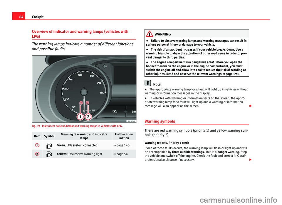
Overview of indicator and warning lamps (vehicles with
LPG)
The warning lamps indicate a number of different functions
and possible faults.
Fig. 39 Instrument panel indicator and warning lamps in vehicles with LPG.
ItemSymbolMeaning of warning and indicator
lampsFurther infor-mation
1Green: LPG system connected⇒ page 140
2Yellow: Gas reserve warning light⇒ page 54
WARNING
● Failure to observe warning lamps and warning messages can result in
serious personal injury or damage to your vehicle.
● The risk of an accident increases if your vehicle breaks down. Use a
warning triangle to draw the attention of other road users in order to pre-
vent danger to third parties.
● The engine compartment is a dangerous area! Before you open the
bonnet to work on the engine or in the engine compartment, you must
switch the engine off and allow it to cool to reduce the risk of scalding or
other injuries. Read and observe the relevant warnings ⇒ page 193.
Note
● The appropriate warning lamp for a fault will light up in vehicles without
warning or information messages in the display.
● In vehicles with warning or information texts on the screen, the appro-
priate warning lamp for a fault will light up and a warning or information
message will also appear on the screen.
Warning symbols
There are red warning symbols (priority 1) and yellow warning sym-
bols (priority 2) Warning reports, Priority 1 (red)
If one of these faults occurs, the warning lamp will flash or light up and will
be accompanied by three audible warnings. This is a danger warning. Stop
the vehicle and switch off the engine. Check the fault and correct it. Obtain
professional assistance if necessary.
Page 67 of 278

65
Cockpit
If several priority 1 faults are detected at the same time, the symbols will be
displayed one after the other for about 2 seconds at a time and will contin-
ue until the fault is corrected.
No menus will be shown in the display for the duration of a priority 1 warn-
ing message.
Examples of priority 1 warning messages (red)
● Brake system symbol with the warning message STOP BRAKE FLUID
SERVICE MANUAL or STOP BRAKE FAULT SERVICE MANUAL .
● Coolant symbol with the warning message STOP SEE COOLANT IN-
STRUCTION MANUAL.
● Engine oil pressure symbol with the warning message STOP ENGINE
OIL PRESSURE LOW! INSTRUCTION MANUAL .
Warning reports, Priority 2 (yellow)
If one of these faults occurs, the warning lamp lights up, and is accompa-
nied by one audible warning. Check the corresponding function as soon as
possible although the vehicle may be used without risk.
If several priority 2 warning messages are detected at the same time, the
symbols are displayed one after the other for about 2 seconds at a time. Af-
ter a set time, the information text will disappear and the symbol will be
shown as a reminder at the side of the display.
Priority 2 warning messages will not be shown until all Priority 1 warning
messages have been dealt with!
Examples of priority 2 warning messages (yellow): 1)
● Fuel warning light with the information text PLEASE REFUEL. Information messages displayed on the screen*
Message
a)Description
SERVICEThe service interval has ended. Take the vehicle to an au-
thorised service.
IMMOBILIS-
ERImmobiliser system active. The vehicle will not start. Take
the vehicle to an authorised service.
ERRORInstrument panel faulty. Take the vehicle to an authorised
service.
CLEAN AIRFILTERWarning: Clean the air filter.
NO KEYWarning: Correct key cannot be found in the vehicle.KEY BATTERYWarning: Key battery low. Change the battery.
CLUTCHWarning: Press the clutch to start. In vehicles with manual
gearbox and Start/Stop system.
--> P/NWarning: Place the selector level in P/N to start. Only in ve-
hicles with automatic gearbox.
--> PWarning: Place the selector lever in position P to stop the
engine.
STARTINGWarning: The engine starts automatically. Start-Stop system
activated.
START MAN- UALLYWarning: The engine must be started manually. Start-Stop
system activated.
ERROR
START STOPWarning: Start-Stop system error.
START STOP
IMPOSSIBLEWarning: Although the Start-Stop system is switched on, the
engine cannot be stopped automatically. Not all the neces-
sary conditions are met.
START STOP ACTIVEWarning: Start-Stop system activated. Vehicle in Stop mode.
1)
Depending on the version of the model.
Safety FirstOperating InstructionsPractical TipsTechnical Specifications
Page 75 of 278

73
Cockpit
If the indicator flashes the voltage is insufficient for normal vehicle opera-
tion.
Turn signals
The indicator lamp flashes when the turn signals are in op-
eration.
Depending on which turn signal is operating, either the left or right
turn signal lamp flashes. Both indicator lamps will flash at the same time
when the hazard warning lights are switched on.
If any of both turn signals fails, the indicator lamp will start flashing twice
faster than normal.
For further information on the turn signals, please see ⇒ page 100.
Electronic immobiliser* “Safe”
This warning lamp flashes if an unauthorised key is used.
Inside the key there is a chip that deactivates the electronic immobiliser au-
tomatically when the key is inserted into the ignition. The immobiliser will
be activated again automatically as soon as you pull the key out of the igni-
tion lock.
The instrument panel displays the following message 1)
: SAFE. The vehicle
cannot be started in this case
The engine can, however, be started if the appropriate coded SEAT genuine
key is used.
Note
The vehicle cannot operate properly if you do not have a genuine SEAT key.
1)
Depending on the version of the model.
Safety FirstOperating InstructionsPractical TipsTechnical Specifications
Page 80 of 278

78Unlocking and locking
Once this system is activated, opening doors from the outside and the in-
side is not possible. The tailgate can not be opened. The central locking
button does not work.
When the ignition is switched off, the instrument panel indicates that the
Safe system is on.
Deactivation
Rotate the key inserted in the lock cylinder twice towards the locking direc-
tion.
To activate the system using the remote control, press the lock button on
the remote twice
in less than five seconds.
On deactivating the “Safe” system, the alarm volumetric sensor is also de-
activated.
With the “Safe” switched off, doors can be opened from the interior but not
from the exterior.
See “Selective unlocking system*”
“Safe” status
On the driver door, there is a visible warning lamp which shows the “Safe”
system status.
We will know that “Safe” system is activated by the flashing warning lamp.
The indicator will flash on all vehicles, fitted and nor fitted with an alarm,
until they unlock.
Remember:
Safe activated with or without an alarm: Warning lamp flashes continuous-
ly.
Safe deactivated without an alarm: The indicator remains off.
Safe deactivated with an alarm: The indicator remains off.
WARNING
No one should remain inside the vehicle if the “Safe” mechanism is acti-
vated because opening the doors will not be possible in case of emergen-
cy neither from the inside nor the outside. Danger of death. Passengers
could become trapped inside in case of emergency.
Selective unlocking system*
This system allows to unlock either just the driver door or all
the vehicle.
Driver door unlock button
Unlock once. Use either the key or the remote control.
Once the key is inserted in the lock cylinder, rotate once in the unlock direc-
tion. The driver door will remain without “Safe” and unlocked. See Anti-theft
Alarm chapter for vehicles fitted with an alarm ⇒ page 84.
Using the remote control, press the unlock button on the remote
once.
The Safe system for all the vehicle is deactivated, only the driver door is un-
locked and both the alarm and the warning lamp are also turned off.
Unlocking all doors and the luggage compartment
The unlock button on the remote control must be pressed twice
so that
all doors and the luggage compartment can be opened.
Press twice within 5 seconds to deactivate the Safe system for all vehicle, to
unlock all doors and to use the luggage compartment. The warning lamp
and the alarm (only vehicles fitted with one) are turned off.
Unlocking the luggage compartment
See ⇒ page 87.
Page 89 of 278

87
Unlocking and locking
Tailgate Unlocking and locking
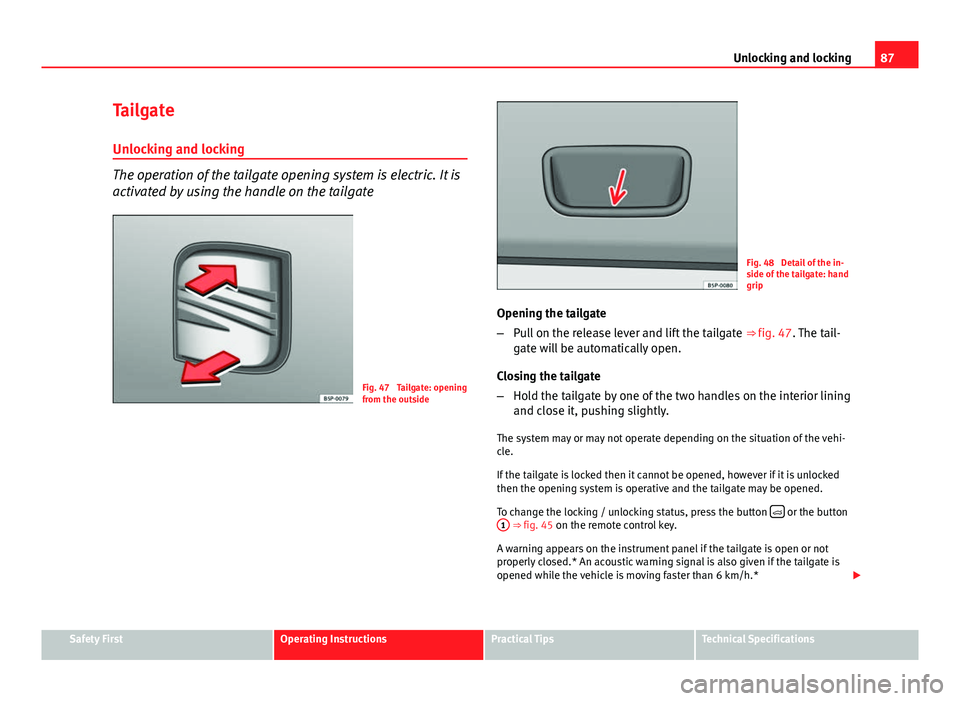
The operation of the tailgate opening system is electric. It is
activated by using the handle on the tailgate
Fig. 47 Tailgate: opening
from the outside
Fig. 48 Detail of the in-
side of the tailgate: hand
grip
Opening the tailgate
– Pull on the release lever and lift the tailgate ⇒ fig. 47. The tail-
gate will be automatically open.
Closing the tailgate
– Hold the tailgate by one of the two handles on the interior lining
and close it, pushing slightly.
The system may or may not operate depending on the situation of the vehi-
cle.
If the tailgate is locked then it cannot be opened, however if it is unlocked
then the opening system is operative and the tailgate may be opened.
To change the locking / unlocking status, press the button
or the button
1 ⇒ fig. 45 on the remote control key.
A warning appears on the instrument panel if the tailgate is open or not
properly closed.* An acoustic warning signal is also given if the tailgate is
opened while the vehicle is moving faster than 6 km/h.*
Safety FirstOperating InstructionsPractical TipsTechnical Specifications