2011 Seat Altea XL wheel
[x] Cancel search: wheelPage 268 of 319

If and when
266The wheel bolts should be clean and easily screwed. Before fitting the spare
wheel, inspect the wheel condition and hub mounting surfaces. These
surfaces must be clean before fitting the wheel.
The hexagonal socket in the screwdriver handle makes it easier to turn the
wheel bolts. The reversible screwdriver blade should be removed when the
tool is used for this purpose.
If tyres with a specific direction of rotation are fitted, note the direction of
rotation.
Note
Do not use the hexagonal socket in the screwdriver handle to loosen or
tighten the wheel bolts.Anti-theft wheel bolts*
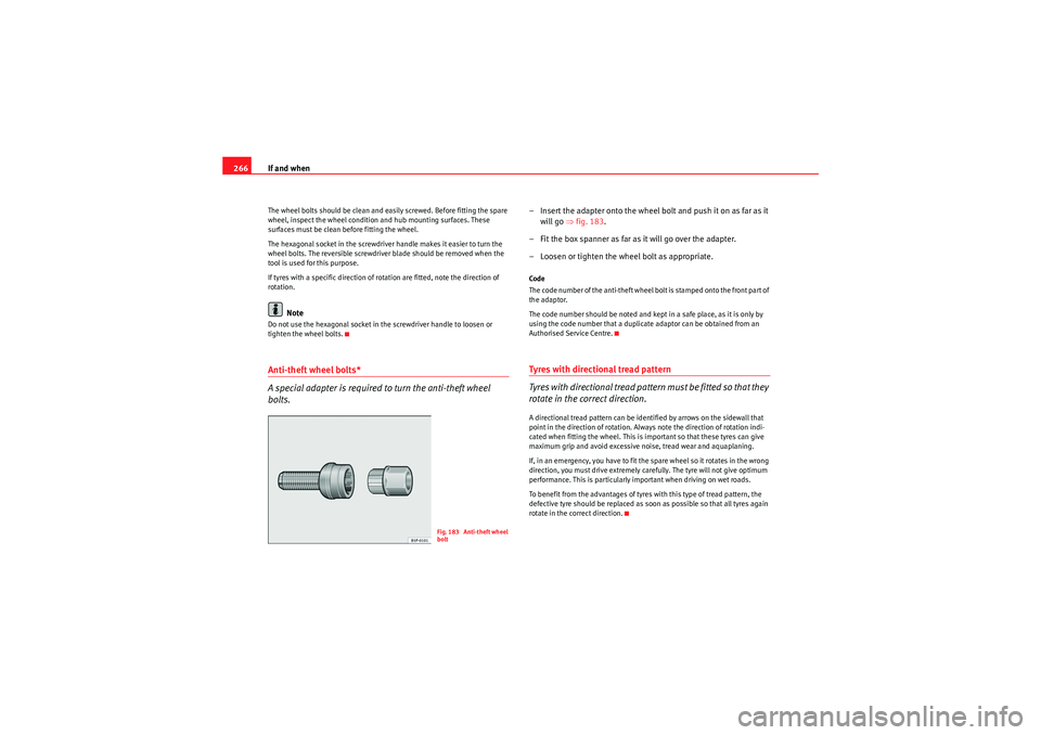
A special adapter is required to turn the anti-theft wheel
bolts.
– Insert the adapter onto the wheel bolt and push it on as far as it
will go ⇒ fig. 183.
– Fit the box spanner as far as it will go over the adapter.
– Loosen or tighten the wheel bolt as appropriate.Code
The code number of the anti-theft wheel bolt is stamped onto the front part of
the adaptor.
The code number should be noted and kept in a safe place, as it is only by
using the code number that a duplicate adaptor can be obtained from an
Authorised Service Centre.Tyres with directional tread pattern
Tyres with directional tread pattern must be fitted so that they
rotate in the correct direction.A directional tread pattern can be identified by arrows on the sidewall that
point in the direction of rotation. Always note the direction of rotation indi-
cated when fitting the wheel. This is important so that these tyres can give
maximum grip and avoid excessive noise, tread wear and aquaplaning.
If, in an emergency, you have to fit the spare wheel so it rotates in the wrong
direction, you must drive extremely carefully. The tyre will not give optimum
performance. This is particularly important when driving on wet roads.
To benefit from the advantages of tyres with this type of tread pattern, the
defective tyre should be replaced as soon as possible so that all tyres again
rotate in the correct direction.
Fig. 183 Anti-theft wheel
bolt
AlteaXL_EN.book Seite 266 Donnerstag, 9. September 2010 12:13 12
Page 269 of 319

If and when267
Safety First
Operating Instructions
Practical Tips
Technical Specifications
Tyre repair kit (Tyre Mobility System)*General information and safety notesYour vehicle is equipped with a tyre repair kit called Tyre Mobilit y System.
In the event of a tyre puncture, a sealing compound and an air compressor are
located in the luggage compartment under the floor panel.
The Tyre Mobility System will reliably seal punctures caused by the penetra-
tion of a foreign body of up to about 4 mm in diameter.
It is not necessary to remove the foreign body from the tyre.
Instructions for the sealing compound are located on the sealing compound
container.
You will also find instructions for operating the compressor.
WARNING
•Do not attempt to repair a puncture with the sealing compound if the
tyre has been damaged by driving the vehicle after the tyre has lost its air.•Always observe warnings and follow instructions concerning
compressor and sealing compound carefully.•Do not drive faster than 80 km/h, avoid heavy acceleration, hard
braking and fast cornering.•Tyres which have been repaired with sealing compound are only suit-
able for temporary use over a short period. Therefore, please drive carefully
to the next available specialised workshop.
For the sake of the environment
If you have to dispose of a sealant can, go to a specialised waste service or to
a SEAT Technical Service, where the product can be recycled in an appropriate
waste container.
Note
•If sealant should leak out, leave it to dry. This way you can pull it off like a
piece of foil.•Observe the expiry date stated on the sealing compound can. Have the
sealing compound exchanged by a specialised workshop.•Seek professional assistance if the repair of a tyre puncture is not
possible with the sealing compound.Preparation work
Certain steps must be taken before repairing a tyre.– If you have a flat tyre or puncture, park the vehicle as far away from the flow of traffic as possible.
–Apply the handbrake firmly.
– Engage first gear , or put the selector lever to position P.
–All passengers should leave the vehicle. They should wait in a
safe area (for instance behind the roadside crash barrier).
– Check whether a repair is possibl e using the Tyre Mobility System
“General information and safety notes.”
– Unscrew inflation cap from the affected wheel.
AlteaXL_EN.book Seite 267 Donnerstag, 9. September 2010 12:13 12
Page 271 of 319

If and when269
Safety First
Operating Instructions
Practical Tips
Technical Specifications
FusesChanging a fuse
Blown fuses must be replaced
Fuse cover underneath the steering wheel
– Switch off the ignition and the component concerned.
– Identify the fuse corresponding to the damaged electric
consumer ⇒page 271.
– Take the plastic clip from inside the fuse cover, fit it onto the blown fuse and pull the fuse out.
– Replace the blown fuse (which will have a melted metal strip) with a new fuse of the same ampere rating.
Fuse cover in engine compartment
– Switch off the ignition and its failed electrical component.
– Remove the fuse cover in the engine compartment by pressing the tabs towards the centre of the cover ⇒fig. 185 .
– Identify the fuse for the affected component ⇒ page 271.
– Take the plastic clip from inside the fuse cover (at left-hand end of the dash panel), fit it onto the blown fuse and pull the fuse out.
– Replace the blown fuse (which will have a melted metal strip) with a new fuse of the same ampere rating.
– Carefully fit the fuse cover back on to ensure no water can enter the fuse box.The individual electrical circuits are protected by fuses. The fuses are located
behind a cover at the left-hand end of the dash panel and on the left-hand
side of the engine compartment.
Fig. 184 Left side of dash
panel: Fuse box coverFig. 185 Fuse box cover
in engine compartment
AlteaXL_EN.book Seite 269 Donnerstag, 9. September 2010 12:13 12
Page 288 of 319

If and when
286Do not pull too hard with the towing vehicle and take care to avoid jerking the
tow-rope. When towing on an unpaved road, there is always a risk of over-
loading and damaging the anchorage points.
The ignition of the vehicle being towed must be switched on to prevent the
steering wheel from locking and also to allow the use of the turn signals,
horn, windscreen wipers and washers.
As the brake servo does not work if the engine is not running, you must apply
considerably more pressure to the brake pedal than you normally would.
As the power assisted steering does not work if the engine is not running, you
will need more strength to steer than you normally would.•The vehicle must not be towed faster than 50 km/h.•The vehicle must not be towed faster than 50 km/h.
Towing vehicles with an automatic gearbox•Put the selector lever into position “N”.•Do not drive faster than 50 km/h.•Do not tow further than 50 km.•If a breakdown vehicle is used, the vehicle must be towed with the front
wheels raised.Note
•Observe legal requirements when towing or tow-starting.•Switch on the hazard warning lights of both vehicles. However, observe
any regulations to the contrary.•For technical reasons, vehicles with an automatic gearbox must not be
tow-started.•If damage to your vehicle means that there is no lubricant in the gearbox,
you must raise the drive wheels while the vehicle is being towed.
•If the vehicle has to be towed more than 50 km, the front wheels should
be raised during towing, and towing should be carried out by a qualified
person.•The steering wheel is locked when the vehicle has no electrical power. The
vehicle must then be towed with the front wheels raised. Towing should be
carried out by a qualified person.•The towing eye should always be kept in the vehicle.
AlteaXL_EN.book Seite 286 Donnerstag, 9. September 2010 12:13 12
Page 292 of 319

Description of specifications
290Vehicle identification data
The most important information is given on the identification
plate and the vehicle data sticker.Vehicles for certain export countries do not have an identification plate.
Identification plate
The identification plate is located on the left rib inside the engine compart-
ment.
Vehicle identification number
The vehicle identification number (chassis number) can be read from outside
the vehicle through a viewer in the windscreen. This is located on the left-
hand side of the vehicle in the lower area of the windscreen. It is also located
on the right hand side of the engine compartment. Vehicle data
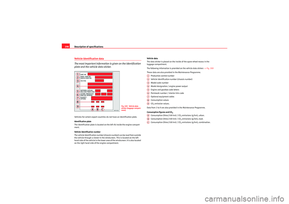
The data sticker is placed on the inside of the spare wheel recess in the
luggage compartment.
The following information is provided on the vehicle data sticker:
⇒fig. 209
These data are also provided in the Maintenance Programme. Production control number
Vehicle identification number (chassis number)
Model code number
Model designation / engine power output
Engine and gearbox code letters
Paintwork number / interior trim code
Optional equipment codes
Consumption values
CO
2 emission values.
Data from 2 to 9 are also provided in the Maintenance Programme.
Consumption figures and CO
2
Consumption (litres/100 km) / CO
2 emissions (g/km), urban.
Consumption (litres/100 km) / CO2 emissions (g/km), road.
Consumption (litres/100 km) / CO2 emissions (g/km), combination.
Fig. 209 Vehicle data
sticker (luggage compart-
ment)
A1A2A3A4A5A6A7A8A9AAABAC
AlteaXL_EN.book Seite 290 Donnerstag, 9. September 2010 12:13 12
Page 294 of 319

Description of specifications
292If the maximum permissible drawbar load cannot be met (e.g. with small,
empty and light-weight single axle trailers or tandem axle trailers with a
wheelbase of less than 1 metre), at least 4% of the actual trailer weight is a
legal stipulation for a drawbar load.
WARNING
•For safet y reas ons , d o not excee d the 8 0 k m/h limit . Th is is als o valid in
countries where higher speeds are permitted.•Never exceed the maximum trailer weights or the drawbar load. If the
permissible axle load or the permissible total weight is exceeded, the
driving characteristics of the vehicle may change, leading to accidents,
injuries and damage to the vehicle.
AlteaXL_EN.book Seite 292 Donnerstag, 9. September 2010 12:13 12
Page 308 of 319

Technical Specifications
306Dimensions and capacities
Dimensions
Length, width 4467 mm/ 1768 mm
Height at kerb weight 1575 mm
Front and rear projection 913 mm/ 976 mm
Wheelbase 2578 mm
Turning circle 10.7 m
Track width
a)
a)This data will change depending on the type of wheel rim.
Front Rear
1527 mm 1506 mm
1541 mm 1520 mm
Capacities
Fuel tank 55 l. Reserve 7 l.
Windscreen washer fluid container with headlight washer 3 l/ 5.5 l
Ty re p re ss u re
Summer-grade tyres:
The correct tyre pressure can be seen on the sticker on the inside of the tank flap.
Winter tyres:
The pressure of these tyres is the same as the summer tyre pressure plus 0.2 bar.
AlteaXL_EN.book Seite 306 Donnerstag, 9. September 2010 12:13 12
Page 309 of 319

Index307
Index
AABS . . . . . . . . . . . . . . . . . . . . . . . . . . . . . . . . . . . 198
Warning lamp . . . . . . . . . . . . . . . . . . . . . . . . . 84
Accessories . . . . . . . . . . . . . . . . . . . . . . . . . . . . 224
Acoustic signal . . . . . . . . . . . . . . . . . . . . . . . . . . 20
Acoustic warning . . . . . . . . . . . . . . . . . . . . . . . . 174
Adaptive headlights . . . . . . . . . . . . . . . . . . . . . 122
Adjusting the seat belt height . . . . . . . . . . . . . . 27
AFS (cornering lights) . . . . . . . . . . . . . . . . . . . . 123
Air conditioner General notes . . . . . . . . . . . . . . . . . . . . . . . . 170
Air conditioner automatic mode 2C-Climatronic . . . . . . . . . . . . . . . . . . . . . . . 168
Air conditioner* 2C-Climatronic* . . . . . . . . . . . . . . . . . . . . . . 166
Air conditioning* . . . . . . . . . . . . . . . . . . . . . . . . 162
Air recirculation mode 2C-Climatronic . . . . . . . . . . . . . . . . . . . . . . . 170
Manual air conditioner . . . . . . . . . . . . . . . . 164
Airbag covers . . . . . . . . . . . . . . . . . . . . . . . . . . . . 36
Airbag system . . . . . . . . . . . . . . . . . . . . . . . . . . . 30 Curtain airbags . . . . . . . . . . . . . . . . . . . . . . . 41
Front airbags . . . . . . . . . . . . . . . . . . . . . . . . . 34
Side airbags . . . . . . . . . . . . . . . . . . . . . . . . . . 37
Warning lamp . . . . . . . . . . . . . . . . . . . . . . . . . 31
Alarm system Switching off . . . . . . . . . . . . . . . . . . . . . . . . 109 All-wheel drive . . . . . . . . . . . . . . . . . . . . . . . . . . 201
Alternator
Warning lamp . . . . . . . . . . . . . . . . . . . . . . . . . 85
Anti-freeze . . . . . . . . . . . . . . . . . . . . . . . . . . . . . 240
Anti-lock brake system . . . . . . . . . . . . . . . . . . . 198 Warning lamp . . . . . . . . . . . . . . . . . . . . . . . . . 84
Anti-theft alarm Switching off . . . . . . . . . . . . . . . . . . . . . . . . 109
Anti-theft alarm system . . . . . . . . . . . . . . . . . . . 109
Anti-theft wheel bolts . . . . . . . . . . . . . . . . . . . . 262
Aquaplaning . . . . . . . . . . . . . . . . . . . . . . . . . . . 253
Ashtray* . . . . . . . . . . . . . . . . . . . . . . . . . . . . . . . 153
Aspects to note before setting off . . . . . . . . . . . . 8
Automatic anti-dazzle interior mirror* Activating the anti-dazzle function . . . . . . 134
Deactivating anti-dazzle function . . . . . . . . 134
Automatic car wash tunnel . . . . . . . . . . . . . . . . 216
Automatic gearbox Kick-down feature . . . . . . . . . . . . . . . . . . . . 187
Automatic gearbox / DSG automatic gearbox . 183
Automatic lighting . . . . . . . . . . . . . . . . . . . . . . . 119
Automatic windscreen wiper/washer . . . . . . . . 130
Auxiliary audio connection: AUX-IN . . . . . . . . . 155
BBall coupling . . . . . . . . . . . . . . . . . . . . . . . . . . . 212 Battery
Changing . . . . . . . . . . . . . . . . . . . . . . . . . . . 248
Charging . . . . . . . . . . . . . . . . . . . . . . . . . . . . 248
Winter conditions . . . . . . . . . . . . . . . . . . . . 247
Before setting off . . . . . . . . . . . . . . . . . . . . . . . . . . 8
Biodiesel . . . . . . . . . . . . . . . . . . . . . . . . . . . . . . 232
Biodiesel fuel . . . . . . . . . . . . . . . . . . . . . . . . . . . 232
Bonnet . . . . . . . . . . . . . . . . . . . . . . . . . . . . . . . . 235
Brake fluid . . . . . . . . . . . . . . . . . . . . . . . . . . . . . 245 Changing . . . . . . . . . . . . . . . . . . . . . . . . . . . 246
Warning lamp . . . . . . . . . . . . . . . . . . . . . . . . 66
Brake pads . . . . . . . . . . . . . . . . . . . . . . . . . . . . . 205
Brake pedal warning lamp . . . . . . . . . . . . . . . . . . . . . . . . . 89
Brake servo . . . . . . . . . . . . . . . . . . . . . . . 197, 205
Brake system . . . . . . . . . . . . . . . . . . . . . . . . . . . 245 Brake servo . . . . . . . . . . . . . . . . . . . . . . . . . 202
Brakes . . . . . . . . . . . . . . . . . . . . . . . . . . . . . 202
Warning lamp . . . . . . . . . . . . . . . . . . . . . . . . 86
Brakes . . . . . . . . . . . . . . . . . . . . . . . . . . . . . . . . 205 Worn brake pads . . . . . . . . . . . . . . . . . . . . . . 85
Braking distance . . . . . . . . . . . . . . . . . . . . . . . . 205
Bulb changes General notes . . . . . . . . . . . . . . . . . . . . . . . 273
Bulb defect warning lamp . . . . . . . . . . . . . . . . . . . . . . . . . 86
Buzzer . . . . . . . . . . . . . . . . . . . . . . . . . . . . 125, 174
AlteaXL_EN.book Seite 307 Donnerstag, 9. September 2010 12:13 12