2011 RENAULT SCENIC regeneration
[x] Cancel search: regenerationPage 17 of 329

13B-17
MR-372-J84-13B050$195.mif
V17
Siemens Injection
SID301 and 304
Vdiag No.: 44-45-48-49-4D-4C
Program No.: B1 and B2DIESEL INJECTION
Fault finding – Function13B
AIR SUPPLY
Measurement of the fresh air flow
The flow of fresh air entering the engine is measured by a flow sensor (ratiometric hot-wire sensor).
A fresh air temperature sensor is integrated into the air flowmeter.
EGR valve control
The EGR (exhaust gas recirculation) system consists of a direct current EGR valve fitted with a valve position
sensor. The EGR valve is controlled in a closed-loop via the position sensor. Up to a certain rate, exhaust gas
recirculation enables nitrogen oxide (NOx) emissions to be reduced significantly.
Turbocharger control
The turbocharger system consists of a solenoid valve connected to the vacuum pump circuit, which controls the
vanes via a diaphragm to create an overpressure or a vacuum in the fresh air inlet circuit (the overpressure can
reach 2.6 bar).
Damper valve control (for Vdiag 44, 45, 48, 49 and 4D only)
By default the valve is open when in the rest position and is actuated only when the engine is switched off; this has
a damping effect and helps to stop the engine.
It also controls the flow of fresh air during regeneration.
IDLE SPEED MANAGEMENT
The injection computer regulates the idle speed according to the idle speed setpoint which it calculates.
The idle speed setpoint is dependent on:
– the coolant temperature,
– the emission control programs,
– air conditioning requirements,
– the gear ratio engaged (automatic or sequential gearbox),
– the electrical consumers,
– battery voltage.
ENGINE TORQUE MANAGEMENT
The torque structure is the system which translates the driver's request into a torque supplied by the engine. Certain
functions such as the electronic stability program (ESP), the automatic gearbox (BVA) or the sequential gearbox
(BVR), if fitted to the vehicle, use this information.
Each inter-system (ESP, automatic gearbox, sequential gearbox) sends the injection computer a torque request via
the multiplex network.
The injection computer arbitrates between the inter-system torque requests and the driver request (depressing the
accelerator pedal or setting the cruise control/speed limiter function). The result of the arbitration gives the torque
setpoint.
From this torque set point, the computer determines the quantity of fuel to be injected (injection duration and number
of injection processes) and the amount of air required (turbocharging pressure and EGR valve rate) so that the
engine is able to provide the torque required in the best possible conditions (in terms of smooth running
performance, pollutant emissions, etc.).
Page 19 of 329

13B-19
MR-372-J84-13B050$195.mif
V17
Siemens Injection
SID301 and 304
Vdiag No.: 44-45-48-49-4D-4C
Program No.: B1 and B2DIESEL INJECTION
Fault finding – Function13B
INTERSYSTEM EXCHANGES
The inter-system connections concerning the particular requirements of engine management are as follows:
●Request for injection computer to switch on the OBD warning light to warn of an OBD related pollution fault.
●Request to switch on the Level 1 warning light to warn of an operational safety fault with the engine
management system which may restrict performance.
●Request to switch on the Level 2 warning light to warn of an operational safety fault with the engine
management system which may result in the engine stopping.
●Request to switch on the Particle Filter and Service warning light to warn of an operational safety fault of the
particle filter system which may result in reduced performance or engine stoppage.
●Request to switch on the Engine overheating warning light to warn of an engine overheating fault or a fault
in the coolant temperature sensor.
●Request to switch on the Particle filter warning light to warn the driver that the particle filter is loaded with
particles (weight of soot more than 30.8 g). As soon as possible, the driver must drive at a speed of more than
25 mph (40 km/h) for 2 minutes to activate regeneration.
The driver must maintain a speed of more than 25 mph (40 km/h) until the particle filter warning light goes out
(Vdiag 45 and 49 only).
●Request to start the fan assembly for engine cooling and also for air conditioning purposes,
●Request to switch off the air conditioning compressor for engine programming requirements such as pulling
away, performance, anti-stalling, overspeed, etc.
●Request to switch off electrical consumers (passenger compartment heating resistor (if fitted), heated rear
screen, etc.) for engine operation purposes such as: pulling away, performance, anti-stalling,
overspeed, etc.
●Formulation of requests to engage electrical consumers and limit power as a function of rail conditions.
This last function is made possible with the introduction of alternator control. Formulation of requests enables
the smooth running of the engine to be improved in the critical operating phases, mainly at idle speed and
when pulling away. These requests pass via the multiplex network to the Protection and Switching Unit where
they are converted before being sent to the alternator.
In comparison to the version without a particle filter (K9K Step 2), the K9K Step 2 particle filter technical
specifications also include:
●Four temperature sensors spread along the exhaust system.
●One differential pressure sensor.
●One fuel injector with a dedicated electric fuel pump.
●An electric water pump (in addition to the mechanical pump) controlled by a relay to cool the turbocharger when
the engine is stopped (only for Clio III, Modus and Mégane II/Scénic II).
●Four heating elements and their control unit.
Oil Control System (OCS) (except Vdiag 44, 45 and 49)
This program takes into account the driving style of the user to warn him of the need for an oil change. This program
counts the number of miles since the last oil change, corrected by a factor which depends on the oil temperature.
When the number of miles exceeds a threshold, the customer is warned by a message to the instrument panel that
the drain must be performed.
After the oil change, the user must reset the oil change interval on the instrument panel.
Page 20 of 329

13B-20
MR-372-J84-13B050$195.mif
V17
Siemens Injection
SID301 and 304
Vdiag No.: 44-45-48-49-4D-4C
Program No.: B1 and B2DIESEL INJECTION
Fault finding – Function13B
The exhaust system is fitted with an exhaust gas treatment system consisting of (in order):
●A shell casing containing an oxidation catalytic converter to treat hydrocarbons and carbon monoxide, the volume
and positioning of which is identical to K9K Step 2 without a particle filter.
●A fuel injector supplied by a second fuel circuit which is independent of the main fuel circuit.
●A second casing containing an oxidation catalytic converter and a particle filter positioned under the vehicle floor.
EXHAUST GAS TREATMENT
Operating principle
Regeneration consists of burning the particles accumulated in the filter. When oxygen is present, regeneration
by particle combustion occurs naturally when the exhaust gas temperature reaches 570°C.
This temperature is very different to the temperatures observed in the normal operating range of a common rail
engine. In town, the engine does not produce much heat and the exhaust gas temperature varies between 250°C
and 300°C. Whatever the driving conditions may be, a particle filter regeneration program should be developed
without an effect on driving pleasure.
A differential pressure sensor monitors the status of the particle filter (particle weight) and triggers regeneration.
Regeneration is performed by specific injection regulation (phased injection and post-injection) which brings the
temperature of the exhaust gas to between 550 °C and 650 °C at the particle filter inlet.
Regeneration lasts at least 30 minutes and is carried out every 165 miles (275 km) (minimum interval between 2
successful regenerations).
Certain types of customer driving (mainly urban driving) may cause the particle filter to accumulate a significant
quantity of particles. This amount of soot may impair customer experience: poor vehicle performance due to
excessive pressure in the exhaust system.
This driving type may cause the speed request (Vdiag 45 and 49 only) warning light to come on when the particle
weight reaches 30.8 g or after 10 regeneration failures or if the distance between each regeneration reaches
111 0 m il es (1850 km). The customer is asked to drive in a certain way (see vehicle handbook).
However, this warning may be misinterpreted or taken to be a vehicle fault. The vehicle must not be returned to the
garage after such a warning; if the vehicle is taken back to the garage and accepted for repair, the mechanic should
carry out After-Sales regeneration.
PARTICLE FILTER INJECTOR PROGRAM
The particle filter injector is clamped in place inside a cooling cylinder head, which itself is attached to the output
cone of the first oxidation catalytic converter. The coolant flows into the cylinder head via a take-off pipe on the
cooling system and leaves via a hose connected to the turbocharger.
This injector is used to replace post injection in areas of low load and low flow.
This injector is supplied by an additional electric fuel pump.
The electric fuel pump is:
●controlled by a relay during each regeneration phase or purge,
●integrated into the suction module submerged in the tank,
●connected to the second fuel circuit.
Page 22 of 329

13B-22
MR-372-J84-13B050$195.mif
V17
Siemens Injection
SID301 and 304
Vdiag No.: 44-45-48-49-4D-4C
Program No.: B1 and B2DIESEL INJECTION
Fault finding – Function13B
High pressure pump:
The pump draws in fuel from the tank, which passes through a fuel filter and supplies the fuel injectors.
Rail pressure sensor:
This sensor is fitted to the rail and shows the pressure inside the rail.
Rail pressure regulator:
This component regulates the high pressure of the fuel in the injection system.
Fuel flow regulator:
This component regulates the fuel flow of the injection system.
Fuel temperature sensor:
This sensor measures the temperature of the fuel arising from the pump and injector return.
Piezoelectric injectors:
These injectors enable rapid, precise metering of the quantity of fuel injected, with excellent injection process
repetitiveness.
Vacuum pump:
The vacuum pump is driven by the camshaft. The pump provides the vacuum required to operate the following
components: control solenoid valve, brake servo.
Control solenoid valve:
The solenoid valve connects the vacuum pump and the control diaphragm of the turbocharger blades.
Turbocharger:
The turbocharger is used to supply the engine with more air.
Intake air pressure sensor:
This sensor measures the pressure at the turbocharging air cooler output before the damper valve.
Turbocharger pressure sensor:
This sensor measures the pressure at the turbocharging air cooler output before the damper valve.
Air mass flow meter:
The flowmeter measures the amount of fresh air which goes back into the engine.
EGR valve:
The exhaust gas recirculation enables nitrogen oxide (NOx) emissions to be reduced significantly.
EGR position sensor:
The sensor gives the position of the EGR solenoid valve.
Damper valve (Vdiag 44, 45, 48, 49 and 4D only):
The damper valve is used:
– During regeneration in order to control the flow of fresh air.
– When the engine is switched off, to dampen the engine which helps stop the engine.
– When inoperative, the damper valve is by default in the fully open position.
Particle filter:
The particle filter retains the particles for destruction during regeneration, avoiding propagation of these particles in
the atmosphere (Vdiag 45, 49, 4D only).
Page 23 of 329

13B-23
MR-372-J84-13B050$195.mif
V17
Siemens Injection
SID301 and 304
Vdiag No.: 44-45-48-49-4D-4C
Program No.: B1 and B2DIESEL INJECTION
Fault finding – Function13B
TDC sensor:
The angular position is measured using a magneto-inductive sensor triggered by machined teeth on the flywheel.
This sensor gives the engine speed and the position of the crankshaft for injection.
Camshaft sensor:
This sensor gives a signal to perform the injection cycle. When the piston of cylinder 1 is at top dead centre, either at
the end of the compression stroke or at the end of the exhaust stroke, the camshaft sensor enables a distinction to
be made between these two states.
Electric coolant pump:
The electric coolant pump is activated when the coolant temperature has reached a significant temperature
threshold when the engine has stopped.
The role of the electric water pump is to cool the turbocharger when the engine stops (Vdiag 45, 49 only).
Refrigerant pressure sensor:
The role of the sensor is to measure the refrigerant fluid pressure in the air conditioning circuit.
Electric fuel pump:
The pump is controlled by a relay during each regeneration or purge phase; it is submerged in the tank and is
connected to the secondary fuel circuit only.
Coolant temperature sensor:
The engine coolant temperature sensor informs the computer about the engine coolant temperature.
Air temperature sensor:
The air temperature sensor is fitted in the inlet manifold and informs the computer about the temperature of the air
sucked up by the engine.
Turbocharging pressure sensor solenoid valve:
This solenoid valve operates the turbocharger wastegate pneumatic circuit to lower the turbocharging pressure.
Catalytic converter:
Its role is to convert pollutant gases into harmless gases.
Catalytic converter downstream temperature sensor:
This sensor gives the temperature of the exhaust gas at the catalytic converter output.
Turbine upstream temperature sensor:
This sensor gives the temperature of the exhaust gas at the turbine inlet.
Particle filter downstream temperature sensor:
This sensor gives the exhaust gas temperature at the particle filter outlet (Vdiag 45, 49, 4D only).
Particle filter upstream temperature sensor:
This sensor gives the exhaust gas temperature at the particle filter inlet (Vdiag 45, 49, 4D only).
Particle filter differential pressure sensor:
A differential pressure sensor monitors the status of the particle filter (particle weight) and triggers regeneration.
The role of the sensor is to inform the computer of the pressure difference between particle filter inlet and outlet
(Vdiag 45, 49, 4D only).
Page 24 of 329

13B-24
MR-372-J84-13B050$195.mif
V17
Siemens Injection
SID301 and 304
Vdiag No.: 44-45-48-49-4D-4C
Program No.: B1 and B2DIESEL INJECTION
Fault finding – Function13B
Cruise control/speed limiter on/off switch:
This switch turns the cruise control/speed limiter on or off.
Water in diesel fuel sensor (optional):
This sensor indicates if water is present in the diesel.
Fan unit relay:
This relay actuates the motor-driven fan assemblies when a temperature threshold has been exceeded.
Accelerator potentiometer:
The accelerator potentiometer informs the computer about the position of the accelerator pedal (engine load).
Brake pedal switch:
The brake pedal switch informs the computer about the pedal status.
Clutch pedal switch:
The clutch pedal switch informs the computer about the pedal status.
Particle filter injector:
The particle filter injector is a low pressure injector. This injector allows the temperature of the second catalytic
converter to be raised to assist with regeneration of the particle filter (Vdiag 45, 49, 4D only).
Only on Kangoo 2: an evaporator plate is present at the particle filter injector outlet, at the level of the bracket
between the exhaust pipe and the catalytic converter.
Heating elements:
The heating elements heat the engine coolant to enhance user comfort (Vdiag 45, 49, 4D only).
Heater plugs:
The heater plugs preheat the combustion chamber so that the explosion of the fuel mixture occurs under the best
conditions to start the engine.
Page 27 of 329
13B-27
MR-372-J84-13B050$273.mif
V17
Siemens Injection
SID301 and 304
Vdiag No.: 44-45-48-49-4D-4C
Program No.: B1 and B2DIESEL INJECTION
Fault finding – Replacement of components13B
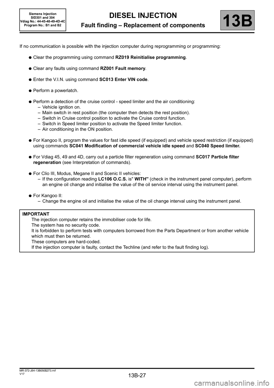
If no communication is possible with the injection computer during reprogramming or programming:
●Clear the programming using command RZ019 Reinitialise programming.
●Clear any faults using command RZ001 Fault memory.
●Enter the V.I.N. using command SC013 Enter VIN code.
●Perform a powerlatch.
●Perform a detection of the cruise control - speed limiter and the air conditioning:
– Vehicle ignition on.
– Main switch in rest position (the computer then detects the rest position).
– Switch in Cruise control position to activate the Cruise control function.
– Switch in Speed limiter position to activate the Speed limiter function.
– Air conditioning in the ON position.
●For Kangoo II, program the values for fast idle speed (if equipped) and vehicle speed restriction (if equipped)
using commands SC041 Modification of commercial vehicle idle speed and SC040 Speed limiter.
●For Vdiag 45, 49 and 4D, carry out a particle filter regeneration using command SC017 Particle filter
regeneration (see Interpretation of commands).
●For Clio III, Modus, Megane II and Scenic II vehicles:
– If the configuration reading LC106 O.C.S. is" WITH" (check in the instrument panel computer), perform
an engine oil change and initialise the value of the oil service interval using the instrument panel.
●For Kangoo II:
– Change the engine oil and initialise the value of the oil change interval using the instrument panel.
IMPORTANT
The injection computer retains the immobiliser code for life.
The system has no security code.
It is forbidden to perform tests with computers borrowed from the Parts Department or from another vehicle
which must then be returned.
These computers are hard-coded.
If the injection computer is faulty, contact the Techline (and refer to the fault finding log).
Page 30 of 329

13B-30
MR-372-J84-13B050$312.mif
V17
13B
DIESEL INJECTION
Fault finding – Configurations and programming
SPECIAL COMMANDS
SC001: Write saved data.
Use this command after replacing or (re)programming the computer (if the data has been saved using command
SC003).
SC003: Save computer data.
This command enables the computer operating data, the engine adaptives, to be recorded.
Use this command before replacing or (re)programming a computer.
SC013: Enter VIN.
This command permits manual entry of the vehicle's VIN into the computer.
Use this command each time the computer is replaced or (re)programmed.
SC017: Particle filter regeneration.
The regeneration command is used to burn particles which have accumulated in the filter.
Run this command when the particle filter is clogged.
SC040: Speed limiter (Kangoo II only).
This command enables the vehicle's speed to be restricted to a certain speed.
Use this command at the customer's request.
SC041: Modification of the commercial vehicle idle speed (Kangoo II only).
This command enables the idle speed for vehicles such as refrigerated vehicles, ambulances etc. to be increased or
decreased.
CONFIGURATION READING
LC005: Gearbox type.
Manual gearbox or automatic transmission/sequential gearbox
LC009: Air conditioning.
With or without.
LC065: Water in diesel fuel sensor.
With or without.
LC120: Cruise control.
With or without.
LC121: Speed limiter.
With or without.
MR-372-J84-13B050$312.mif
Siemens Injection
SID301 and 304
Vdiag No.: 44-45-48-49-4D-4C
Program No.: B1 and B2