2011 RENAULT SCENIC clutch
[x] Cancel search: clutchPage 7 of 329

13B-7
MR-372-J84-13B050$078.mif
V17
13B
DIESEL INJECTION
Fault finding – Cleanliness guidelines
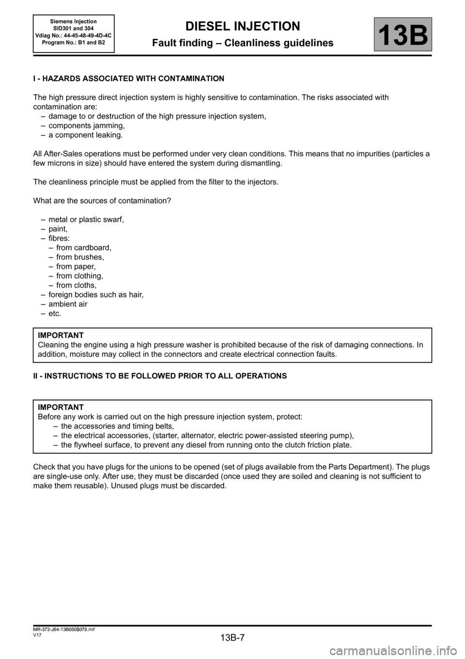
I - HAZARDS ASSOCIATED WITH CONTAMINATION
The high pressure direct injection system is highly sensitive to contamination. The risks associated with
contamination are:
– damage to or destruction of the high pressure injection system,
– components jamming,
– a component leaking.
All After-Sales operations must be performed under very clean conditions. This means that no impurities (particles a
few microns in size) should have entered the system during dismantling.
The cleanliness principle must be applied from the filter to the injectors.
What are the sources of contamination?
– metal or plastic swarf,
– paint,
–fibres:
– from cardboard,
– from brushes,
– from paper,
– from clothing,
– from cloths,
– foreign bodies such as hair,
–ambient air
–etc.
II - INSTRUCTIONS TO BE FOLLOWED PRIOR TO ALL OPERATIONS
Check that you have plugs for the unions to be opened (set of plugs available from the Parts Department). The plugs
are single-use only. After use, they must be discarded (once used they are soiled and cleaning is not sufficient to
make them reusable). Unused plugs must be discarded.IMPORTANT
Cleaning the engine using a high pressure washer is prohibited because of the risk of damaging connections. In
addition, moisture may collect in the connectors and create electrical connection faults.
IMPORTANT
Before any work is carried out on the high pressure injection system, protect:
– the accessories and timing belts,
– the electrical accessories, (starter, alternator, electric power-assisted steering pump),
– the flywheel surface, to prevent any diesel from running onto the clutch friction plate.
MR-372-J84-13B050$078.mif
Siemens Injection
SID301 and 304
Vdiag No.: 44-45-48-49-4D-4C
Program No.: B1 and B2
Page 10 of 329

13B-10
MR-372-J84-13B050$117.mif
V17
Siemens Injection
SID301 and 304
Vdiag No.: 44-45-48-49-4D-4C
Program No.: B1 and B2DIESEL INJECTION
Fault finding – List and location of components13B
Heating elements:
The heating elements are located in the cooling circuit before the additional coolant pump which cools the
turbocharger (Vdiag 45, 49 and 4D only).
Coolant temperature sensor:
The sensor is located on the cylinder head near the engine water chamber.
Air temperature sensor:
The air temperature sensor is located at the air circuit inlet, integrated into the air flowmeter.
Turbocharging pressure sensor solenoid valve:
The solenoid valve is located on the turbocharger.
Catalytic converter:
The catalytic converter is located upstream of the exhaust system and downstream of the turbocharger.
Fuel temperature sensor:
The sensor is located near the injection pump and injector return.
Catalytic converter downstream temperature sensor:
The sensor is located after the catalytic converter.
Turbine upstream temperature sensor:
This sensor is located between the exhaust pipe and the turbocharger.
Cruise control/speed limiter on/off switch:
This switch is located in the passenger compartment to the left of the steering wheel near the lighting dimmer.
Water in diesel fuel sensor (optional):
This sensor is located in the diesel filter.
Fan unit relay:
The relay is located on the cooling radiator.
Accelerator potentiometer:
The potentiometer is located on the accelerator pedal.
Brake pedal switch:
The switch is located on the brake pedal.
Clutch pedal switch:
The switch is located on the clutch pedal.
Heater plugs:
The heater plugs are located on the cylinder head.
Particle filter injector:
The injector is located between the particle filter injector fuel pump and the exhaust pipe. (Vdiag 45, 49 and 4D only)
Electric fuel pump:
The pump is located between the tank and the particle filter injector fuel filter. (Vdiag 45, 49 and 4D only)
Page 12 of 329

13B-12
MR-372-J84-13B050$156.mif
V17
13B
DIESEL INJECTION
Fault finding – Operating diagram
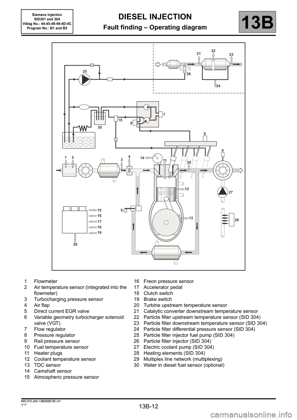
1 Flowmeter
2 Air temperature sensor (integrated into the
flowmeter)
3 Turbocharging pressure sensor
4 Air flap
5 Direct current EGR valve
6 Variable geometry turbocharger solenoid
valve (VGT)
7 Flow regulator
8 Pressure regulator
9 Rail pressure sensor
10 Fuel temperature sensor
11 Heater plugs
12 Coolant temperature sensor
13 TDC sensor
14 Camshaft sensor
15 Atmospheric pressure sensor16 Freon pressure sensor
17 Accelerator pedal
18 Clutch switch
19 Brake switch
20 Turbine upstream temperature sensor
21 Catalytic converter downstream temperature sensor
22 Particle filter upstream temperature sensor (SID 304)
23 Particle filter downstream temperature sensor (SID 304)
24 Particle filter differential pressure sensor (SID 304)
25 Particle filter injector fuel pump (SID 304)
26 Particle filter injector (SID 304)
27 Electric coolant pump (SID 304)
28 Heating elements (SID 304)
29 Multiplex line network (multiplexing)
30 Water in diesel fuel sensor (optional)
MR-372-J84-13B050$156.mif
Siemens Injection
SID301 and 304
Vdiag No.: 44-45-48-49-4D-4C
Program No.: B1 and B2
Page 24 of 329

13B-24
MR-372-J84-13B050$195.mif
V17
Siemens Injection
SID301 and 304
Vdiag No.: 44-45-48-49-4D-4C
Program No.: B1 and B2DIESEL INJECTION
Fault finding – Function13B
Cruise control/speed limiter on/off switch:
This switch turns the cruise control/speed limiter on or off.
Water in diesel fuel sensor (optional):
This sensor indicates if water is present in the diesel.
Fan unit relay:
This relay actuates the motor-driven fan assemblies when a temperature threshold has been exceeded.
Accelerator potentiometer:
The accelerator potentiometer informs the computer about the position of the accelerator pedal (engine load).
Brake pedal switch:
The brake pedal switch informs the computer about the pedal status.
Clutch pedal switch:
The clutch pedal switch informs the computer about the pedal status.
Particle filter injector:
The particle filter injector is a low pressure injector. This injector allows the temperature of the second catalytic
converter to be raised to assist with regeneration of the particle filter (Vdiag 45, 49, 4D only).
Only on Kangoo 2: an evaporator plate is present at the particle filter injector outlet, at the level of the bracket
between the exhaust pipe and the catalytic converter.
Heating elements:
The heating elements heat the engine coolant to enhance user comfort (Vdiag 45, 49, 4D only).
Heater plugs:
The heater plugs preheat the combustion chamber so that the explosion of the fuel mixture occurs under the best
conditions to start the engine.
Page 32 of 329

13B-32
MR-372-J84-13B050$351.mif
V17
Siemens Injection
SID301 and 304
Vdiag No.: 44-45-48-49-4D-4C
Program No.: B1 and B2DIESEL INJECTION
Fault finding – Fault summary table13B
Tool
faultDiagnostic tool titleAssociated
DTCLevel 1 fault warning
light illuminatedLevel 2 fault warning
light illuminatedOBD warning
light illuminated
DF038Computer 06061.DEF/2.DEF/4.DEF/
5.DEF/6.DEF/7.DEF/
8.DEF/9.DEF/
10.DEF/11.DEF/
12.DEF/13.DEF/
14.DEF/15.DEF/
16.DEF/21.DEF/
22.DEF/23.DEF3.DEF/17.DEF/
18.DEF/19.DEF/
20.DEF15.DEF/
16.DEF/
17.DEF/
18.DEF/
19.DEF/
20.DEF/22.DEF
DF039Inlet air temperature
sensor circuit0110 - -CO.1/CC.0/
1.DEF
DF047Computer feed voltage 0560 - - -
DF049Refrigerant sensor
circuit0530 - - -
DF051Cruise control/speed
limiter function0575 - - -
DF053Rail pressure
regulation function1089 1.DEF/2.DEF 3.DEF/4.DEF/5.DEF -
DF054Turbocharging
solenoid valve control
circuit0045 CO/CC.0/CC.1 - -
DF056Air flowmeter circuit 0100 CO.0/CC.1 - CO.0/CC.1
DF067Damper valve control
circuit0120 CO/CC.0/CC.1 - -
DF070Clutch switch circuit 0830 - - -
DF086Coolant pump relay
control circuit2600 CO/CC.0/CC.1 - -
DF091Vehicle speed signal 0500 - - -
DF097Camshaft sensor
circuit0340 - - -
DF098Fuel temperature
sensor circuit0180 - - -
DF127Brake switch no. 1
circuit0571 - - -
DF129Requested air flow 0101 1.DEF/2.DEF - 1.DEF/2.DEF
DF173Reverse gear signal 0812 - - -
Page 66 of 329

13B-66
MR-372-J84-13B050$429.mif
V17
DIESEL INJECTION
Fault finding – Interpretation of faults
Siemens Injection
SID301 and 304
Vdiag No.: 44-45-48-49-4D-4C
Program No.: B1 and B2
13B
DF070
PRESENT
OR
STOREDCLUTCH SWITCH CIRCUIT
1. DEF: Signal outside upper limit
NOTESConditions for applying the fault finding procedure to a stored fault:
The fault is declared present after a series of actions on the clutch pedal during a
road test (speed greater than 54 mph (90 km/h)).
If the fault is present:
Engine bucking or high engine speed.
Use CLIO III, MODUS, MEGANE II ph2, SCENIC II ph2 and KANGOO II Wiring
diagrams Technical Note.
Check the connection and condition of the clutch switch connector, component code 675 (see MR 392, 385,
364, 370 and 417, Mechanical, 37A, Mechanical component controls, Clutch pedal position sensor:
Removal - Refitting) and the injection computer connector, component code 120 (see MR 392, 385, 364, 370
and 417, Mechanical, 13B, Diesel injection, Diesel injection computer: Removal - Refitting).
If the connectors are faulty and if there is a repair procedure (see Technical Note 6015A, Repairing electrical
wiring, Wiring: Precautions for repair) repair the connector(s); otherwise, replace the wiring.
With the ignition on, check the + 5 V clutch switch signal on connection86D and earth on connectionM (or
NAM for Kangoo II).
If correct:
Check the conformity and adjustment of the clutch switch (position, connection).
– display status ET121 Clutch contact signal:
– when the clutch pedal is engaged, status ET121 should be INACTIVE,
– when the clutch pedal is disengaged, status ET121 should be ACTIVE.
If these checks are not correct, replace the clutch switch (see MR 392, 385, 364, 370 and 417, Mechanical,
37A, Mechanical component controls, Clutch pedal position sensor: Removal - Refitting).
If the supply to the switch is incorrect:
Check the insulation, continuity and the absence of interference resistance on the following connections:
–86D between components 675 and 120,
–M (or NAM for Kangoo II) between components 675 and 120.
If the connection(s) are faulty and there is a repair procedure (see Technical Note 6015A, Repairing electrical
wiring, Wiring: Precautions for repair), repair the wiring, otherwise replace it.
If the fault is still present, contact the Techline.
AFTER REPAIRDeal with any faults displayed by the diagnostic tool.
Clear the computer fault memory.
Carry out a road test followed by another check with the diagnostic tool.
SID301_V44_DF070 / SID304_V45_DF070 / SID301_V48_DF070 / SID304_V49_DF070 / SID304_V4D_DF070 / SID301_V4C_DF070
Page 123 of 329

13B-123
MR-372-J84-13B050$468.mif
V17
DIESEL INJECTION
Fault finding – Interpretation of faults
Siemens Injection
SID301 and 304
Vdiag No.: 44-45-48-49-4D-4C
Program No.: B1 and B2
13B
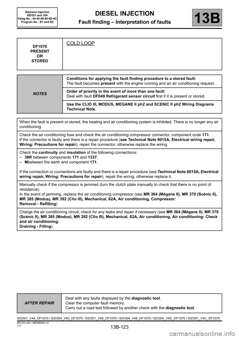
DF1070
PRESENT
OR
STOREDCOLD LOOP
NOTESConditions for applying the fault finding procedure to a stored fault:
The fault becomes present with the engine running and an air conditioning request.
Order of priority in the event of more than one fault:
Deal with fault DF049 Refrigerant sensor circuit first if it is present or stored.
Use the CLIO III, MODUS, MEGANE II ph2 and SCENIC II ph2 Wiring Diagrams
Technical Note.
When the fault is present or stored, the heating and air conditioning system is inhibited. There is no longer any air
conditioning.
Check the air conditioning fuse and check the air conditioning compressor connector, component code 171.
If the connector is faulty and there is a repair procedure (see Technical Note 6015A, Electrical wiring repair,
Wiring: Precautions for repair), repair the connector, otherwise replace the wiring.
Check the continuity and insulation of the following connections:
– 38R between components 171 and 1337,
– Mbetween the earth and component 171.
If the connection or connections are faulty and there is a repair procedure (see Technical Note 6015A, Electrical
wiring repair, Wiring: Precautions for repair), repair the wiring, otherwise replace it.
Manually check if the compressor is jammed (turn the clutch plate manually to check that there is no point of
resistance).
In the event of jamming, replace the air conditioning compressor (see MR 364 (Mégane II), MR 370 (Scénic II),
MR 385 (Modus), MR 392 (Clio III), Mechanical, 62A, Air conditioning, Compressor:
Removal - Refitting)
Charge the air conditioning circuit, check for any leaks and repair if necessary (see MR 364 (Mégane II), MR 370
(Scénic II), MR 385 (Modus), MR 392 (Clio III), Mechanical, 62A, Air conditioning, Air conditioning: Check
and air conditioning:
Draining - Filling).
AFTER REPAIRDeal with any faults displayed by the diagnostic tool.
Clear the computer fault memory.
Carry out a road test followed by another check with the diagnostic tool.
SID301_V44_DF1070 / SID304_V45_DF1070 / SID301_V48_DF1070 / SID304_V49_DF1070 / SID304_V4D_DF1070 / SID301_V4C_DF1070
Page 125 of 329

13B-125
MR-372-J84-13B050$546.mif
V17
13B
DIESEL INJECTION
Fault finding – Status summary table
Tool status Diagnostic tool title
ET001Computer + after ignition feed
ET003Engine immobiliser
ET004 Air conditioning authorisation
ET006Code programmed
ET021High speed fan assembly request
ET022Low speed fan assembly request
ET023Fast idle speed request
ET028Level 1 fault warning light request
ET029Level 2 fault warning light request
ET033EGR solenoid valve
ET038Engine
ET042Cruise control/speed limiter
ET076Starting
ET077Impact detected
ET079Air conditioning present
ET088Compressor actuation request
ET121Clutch switch signal
ET148OBD warning light activation request
ET160Preheating relay control
ET228Cylinder 1 injector control
ET229Cylinder 2 injector control
ET230Cylinder 3 injector control
ET231Cylinder 4 injector control
ET238Synchronisation
ET405Clutch pedal switch
ET415Cruise control/speed limiter deactivation
ET613Fuel pressure regulator
ET638Fuel flow regulator
ET648Engine cooling fan
ET649Water in diesel fuel sensor
ET673Jammed accelerator pedal detected
MR-372-J84-13B050$546.mif
Siemens Injection
SID301 and 304
Vdiag No.: 44-45-48-49-4D-4C
Program No.: B1 and B2