Page 5 of 365

13B-5
MR-372-J84-13B200$036.mif
V13
DIESEL INJECTION
Fault finding – Introduction
EDC16
Program No: C1
Vdiag No: 18, 1C, 20,
50, 58, 5C
13B
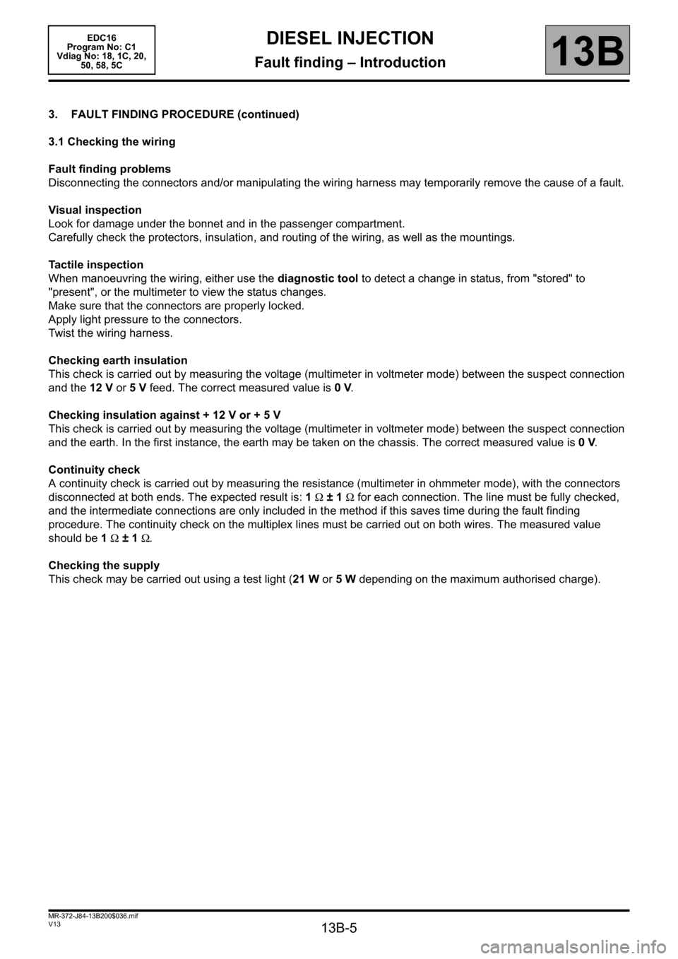
3. FAULT FINDING PROCEDURE (continued)
3.1 Checking the wiring
Fault finding problems
Disconnecting the connectors and/or manipulating the wiring harness may temporarily remove the cause of a fault.
Visual inspection
Look for damage under the bonnet and in the passenger compartment.
Carefully check the protectors, insulation, and routing of the wiring, as well as the mountings.
Tactile inspection
When manoeuvring the wiring, either use the diagnostic tool to detect a change in status, from "stored" to
"present", or the multimeter to view the status changes.
Make sure that the connectors are properly locked.
Apply light pressure to the connectors.
Twist the wiring harness.
Checking earth insulation
This check is carried out by measuring the voltage (multimeter in voltmeter mode) between the suspect connection
and the 12 V or 5V feed. The correct measured value is 0V.
Checking insulation against + 12 V or + 5 V
This check is carried out by measuring the voltage (multimeter in voltmeter mode) between the suspect connection
and the earth. In the first instance, the earth may be taken on the chassis. The correct measured value is 0V.
Continuity check
A continuity check is carried out by measuring the resistance (multimeter in ohmmeter mode), with the connectors
disconnected at both ends. The expected result is: 1Ω±1Ω for each connection. The line must be fully checked,
and the intermediate connections are only included in the method if this saves time during the fault finding
procedure. The continuity check on the multiplex lines must be carried out on both wires. The measured value
should be 1Ω±1Ω.
Checking the supply
This check may be carried out using a test light (21 W or 5W depending on the maximum authorised charge).
Page 290 of 365

13B-290
MR-372-J84-13B200$684.mif
V13
DIESEL INJECTION
Fault finding – Interpretation of parameters
EDC16
Program No: C1
Vdiag No: 18, 1C, 20,
50, 58, 5C
13B
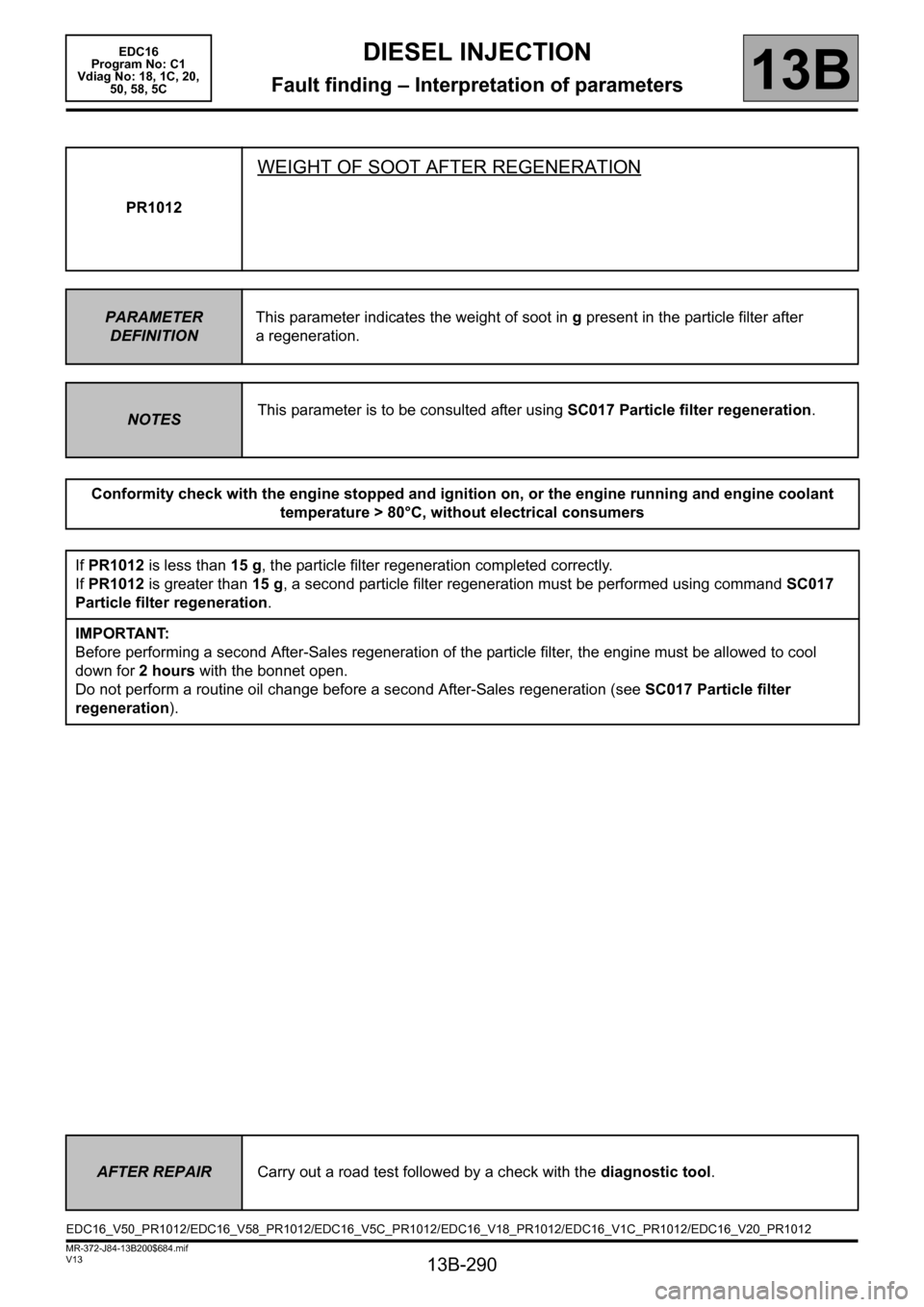
PR1012
WEIGHT OF SOOT AFTER REGENERATION
PARAMETER
DEFINITIONThis parameter indicates the weight of soot in g present in the particle filter after
a regeneration.
NOTESThis parameter is to be consulted after using SC017 Particle filter regeneration.
Conformity check with the engine stopped and ignition on, or the engine running and engine coolant
temperature > 80°C, without electrical consumers
If PR1012 is less than 15 g, the particle filter regeneration completed correctly.
If PR1012 is greater than 15 g, a second particle filter regeneration must be performed using command SC017
Particle filter regeneration.
IMPORTANT:
Before performing a second After-Sales regeneration of the particle filter, the engine must be allowed to cool
down for 2 hours with the bonnet open.
Do not perform a routine oil change before a second After-Sales regeneration (see SC017 Particle filter
regeneration).
AFTER REPAIRCarry out a road test followed by a check with the diagnostic tool.
EDC16_V50_PR1012/EDC16_V58_PR1012/EDC16_V5C_PR1012/EDC16_V18_PR1012/EDC16_V1C_PR1012/EDC16_V20_PR1012
Page 296 of 365

13B-296
MR-372-J84-13B200$756.mif
V13
DIESEL INJECTION
Fault finding – Interpretation of commands
EDC16
Program No: C1
Vdiag No: 18, 1C, 20,
50, 58, 5C
13B
SC017
CONTINUED 1
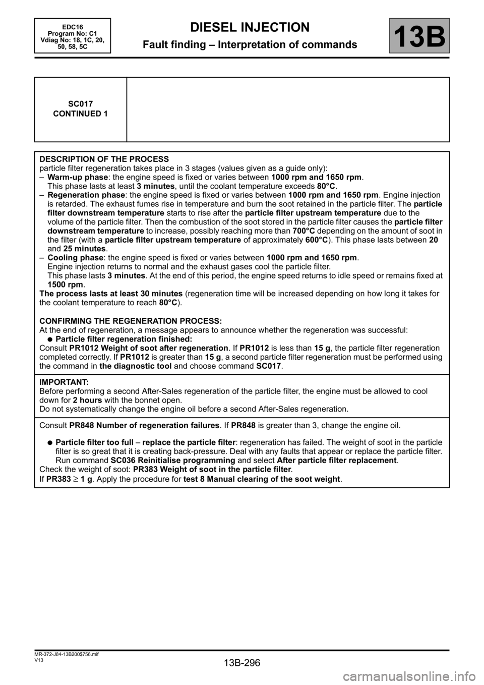
DESCRIPTION OF THE PROCESS
particle filter regeneration takes place in 3 stages (values given as a guide only):
–Warm-up phase: the engine speed is fixed or varies between 1000 rpm and 1650 rpm.
This phase lasts at least 3 minutes, until the coolant temperature exceeds 80°C.
–Regeneration phase: the engine speed is fixed or varies between 1000 rpm and 1650 rpm. Engine injection
is retarded. The exhaust fumes rise in temperature and burn the soot retained in the particle filter. The particle
filter downstream temperature starts to rise after the particle filter upstream temperature due to the
volume of the particle filter. Then the combustion of the soot stored in the particle filter causes the particle filter
downstream temperature to increase, possibly reaching more than 700°C depending on the amount of soot in
the filter (with a particle filter upstream temperature of approximately 600°C). This phase lasts between 20
and 25 minutes.
–Cooling phase: the engine speed is fixed or varies between 1000 rpm and 1650 rpm.
Engine injection returns to normal and the exhaust gases cool the particle filter.
This phase lasts 3 minutes. At the end of this period, the engine speed returns to idle speed or remains fixed at
1500 rpm.
The process lasts at least 30 minutes (regeneration time will be increased depending on how long it takes for
the coolant temperature to reach 80°C).
CONFIRMING THE REGENERATION PROCESS:
At the end of regeneration, a message appears to announce whether the regeneration was successful:
●Particle filter regeneration finished:
Consult PR1012 Weight of soot after regeneration. If PR1012 is less than 15 g, the particle filter regeneration
completed correctly. If PR1012 is greater than 15 g, a second particle filter regeneration must be performed using
the command in the diagnostic tool and choose command SC017.
IMPORTANT:
Before performing a second After-Sales regeneration of the particle filter, the engine must be allowed to cool
down for 2 hours with the bonnet open.
Do not systematically change the engine oil before a second After-Sales regeneration.
Consult PR848 Number of regeneration failures. If PR848 is greater than 3, change the engine oil.
●Particle filter too full – replace the particle filter: regeneration has failed. The weight of soot in the particle
filter is so great that it is creating back-pressure. Deal with any faults that appear or replace the particle filter.
Run command SC036 Reinitialise programming and select After particle filter replacement.
Check the weight of soot: PR383 Weight of soot in the particle filter.
If PR383
≥ 1 g. Apply the procedure for test 8 Manual clearing of the soot weight.