2011 RENAULT SCENIC oil temperature
[x] Cancel search: oil temperaturePage 296 of 365

13B-296
MR-372-J84-13B200$756.mif
V13
DIESEL INJECTION
Fault finding – Interpretation of commands
EDC16
Program No: C1
Vdiag No: 18, 1C, 20,
50, 58, 5C
13B
SC017
CONTINUED 1
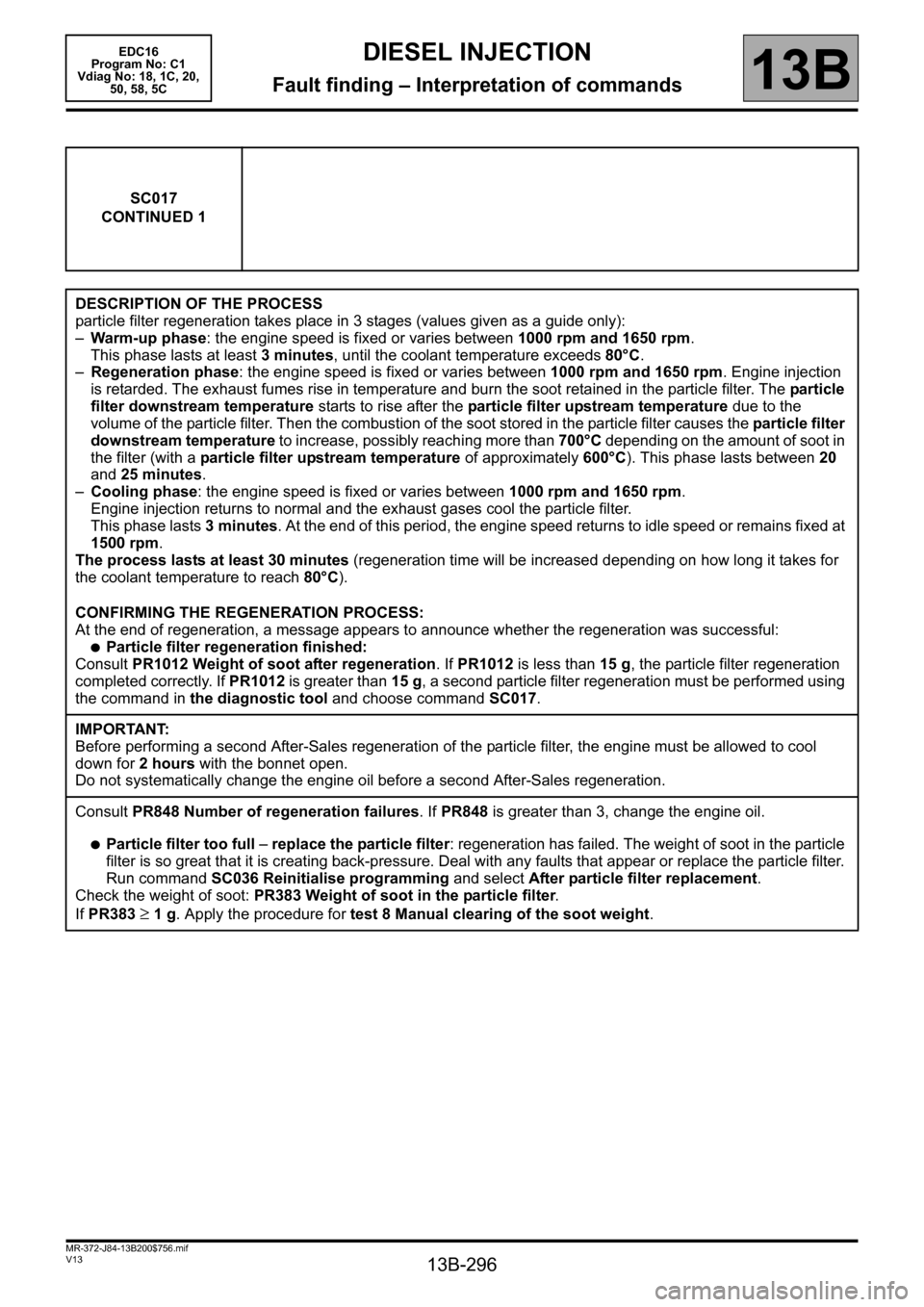
DESCRIPTION OF THE PROCESS
particle filter regeneration takes place in 3 stages (values given as a guide only):
–Warm-up phase: the engine speed is fixed or varies between 1000 rpm and 1650 rpm.
This phase lasts at least 3 minutes, until the coolant temperature exceeds 80°C.
–Regeneration phase: the engine speed is fixed or varies between 1000 rpm and 1650 rpm. Engine injection
is retarded. The exhaust fumes rise in temperature and burn the soot retained in the particle filter. The particle
filter downstream temperature starts to rise after the particle filter upstream temperature due to the
volume of the particle filter. Then the combustion of the soot stored in the particle filter causes the particle filter
downstream temperature to increase, possibly reaching more than 700°C depending on the amount of soot in
the filter (with a particle filter upstream temperature of approximately 600°C). This phase lasts between 20
and 25 minutes.
–Cooling phase: the engine speed is fixed or varies between 1000 rpm and 1650 rpm.
Engine injection returns to normal and the exhaust gases cool the particle filter.
This phase lasts 3 minutes. At the end of this period, the engine speed returns to idle speed or remains fixed at
1500 rpm.
The process lasts at least 30 minutes (regeneration time will be increased depending on how long it takes for
the coolant temperature to reach 80°C).
CONFIRMING THE REGENERATION PROCESS:
At the end of regeneration, a message appears to announce whether the regeneration was successful:
●Particle filter regeneration finished:
Consult PR1012 Weight of soot after regeneration. If PR1012 is less than 15 g, the particle filter regeneration
completed correctly. If PR1012 is greater than 15 g, a second particle filter regeneration must be performed using
the command in the diagnostic tool and choose command SC017.
IMPORTANT:
Before performing a second After-Sales regeneration of the particle filter, the engine must be allowed to cool
down for 2 hours with the bonnet open.
Do not systematically change the engine oil before a second After-Sales regeneration.
Consult PR848 Number of regeneration failures. If PR848 is greater than 3, change the engine oil.
●Particle filter too full – replace the particle filter: regeneration has failed. The weight of soot in the particle
filter is so great that it is creating back-pressure. Deal with any faults that appear or replace the particle filter.
Run command SC036 Reinitialise programming and select After particle filter replacement.
Check the weight of soot: PR383 Weight of soot in the particle filter.
If PR383
≥ 1 g. Apply the procedure for test 8 Manual clearing of the soot weight.
Page 297 of 365

13B-297
MR-372-J84-13B200$756.mif
V13
DIESEL INJECTION
Fault finding – Interpretation of commands
EDC16
Program No: C1
Vdiag No: 18, 1C, 20,
50, 58, 5C
13B
SC017
CONTINUED 2
–Consult PR848 Number of regeneration failures. If this parameter is greater than 3, it is essential to change
the engine oil.
– Explain to the customer the procedure for regeneration when driving to avoid unnecessary repairs: see PART D
in the interpretation of DF312 Speed request.
●Particle filter regeneration failed – run test "Temperature upstream of turbine too low": regeneration
has failed because the temperature upstream of the turbine is too low. Run test 10 Temperature upstream
of turbine too low.
In all cases, carry out the following operations:
– switch off the ignition and wait for the diagnostic tool message (maximum wait 8 minutes): Loss of dialogue
with the computer: EDC16, check the tool connection and the computer supply.
– switch on the ignition and establish dialogue with the injection computer,
– run command SC036 Reinitialise programming,
– depending on the operation performed, select After particle filter regeneration with diag tool, or After
particle filter replacement
– switch off the ignition and wait for the diagnostic tool message (maximum wait 8 minutes): Loss of dialogue
with the computer: EDC16, check the tool connection and the computer supply.
–Then switch on the ignition again, clear the present or stored faults from the computer memory (operation
to be carried out within 3 minutes of switching on the ignition).
Check the weight of soot: PR383 Weight of soot in the particle filter.
If PR383
≥ 1 g. Apply the procedure for test 8 Manual clearing of the soot weight.
If DF308 Clogged particle filter or DF312 Speed request is still present, contact the Techline.
Note:
It is essential to change the engine oil and the oil filter in the following cases:
– following an After-Sales regeneration only if a message on the CLIP diagnostic tool requests it,
– after particle filter replacement following DF311 Number of failed regenerations exceeded (present or stored
before regeneration),
– after a second regeneration (when two successive regenerations).
Page 323 of 365

13B-323
MR-372-J84-13B200$828.mif
V13
DIESEL INJECTION
Fault finding – Fault Finding Chart
EDC16
Program No.: C1
Vdiag no.: 18, 1C, 20,
50, 58, 5C
13B
ALP 4
CONTINUED
Check the injector operation: run test 9.
If the fault is still present
Check the conformity of the accelerator pedal position sensor, the brake pedal sensor, the atmospheric pressure
sensor, the exhaust gas recirculation valve and the damper valve.
Check the consistency of the signal: of the air flowmeter, of the engine coolant temperature sensor, of the fuel
temperature sensor and of the engine speed.
Check the connections, continuity and absence of interference resistance on the air flow sensor (run DF056 Air
flow sensor circuit, 2.DEF), the engine coolant temperature sensor (run DF001 Coolant circuit, 1.DEF), and
the engine speed (run DF195 Engine speed / camshaft sensor consistency, 2.DEF).
Check:
– That the diesel filter is not clogged (for the test, see DF053 Rail pressure regulation function 2.def).
– That there are no leaks on the high and low pressure diesel circuits, run Test 4 Turbocharged air inlet circuit
check.
– That the oil vapour rebreathing system is connected.
– The flow regulator (jammed / seized), apply the interpretation of command AC011 Rail pressure regulator.
– Check the timing setting (and the position of the high pressure pump pinion)
– Check the engine compressions (cylinder compression balance with the Compression test function on the
CLIP Technic tool).
– Measure the engine compressions with the special tool
– If the fault is still present, contact the techline.
AFTER REPAIRCarry out a road test followed by a complete check with the diagnostic tool.
Page 357 of 365

13B-357
MR-372-J84-13B200$936.mif
V13
EDC16
Program No: C1
Vdiag No: 18, 1C, 20,
50, 58, 5CDIESEL INJECTION
Fault finding – Tests13B
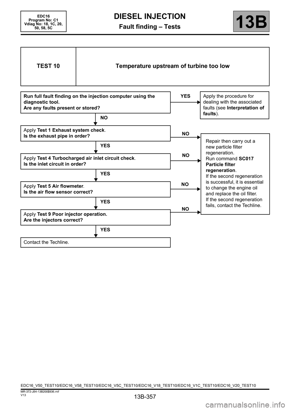
TEST 10 Temperature upstream of turbine too low
Run full fault finding on the injection computer using the
diagnostic tool.
Are any faults present or stored?
NO
Apply Test 1 Exhaust system check.
Is the exhaust pipe in order?
YES
Apply Test 4 Turbocharged air inlet circuit check.
Is the inlet circuit in order?
YES
Apply Test 5 Air flowmeter.
Is the air flow sensor correct?
YES
Apply Test 9 Poor injector operation.
Are the injectors correct?
YES
Contact the Techline.YES
Apply the procedure for
dealing with the associated
faults (see Interpretation of
faults).
NO
Repair then carry out a
new particle filter
regeneration.
Run command SC017
Particle filter
regeneration.
If the second regeneration
is successful, it is essential
to change the engine oil
and replace the oil filter.
If the second regeneration
fails, contact the Techline.
NO
NO
NO
EDC16_V50_TEST10/EDC16_V58_TEST10/EDC16_V5C_TEST10/EDC16_V18_TEST10/EDC16_V1C_TEST10/EDC16_V20_TEST10
Page 359 of 365

13B-359
MR-372-J84-13B200$936.mif
V13
DIESEL INJECTION
Fault finding – Tests
EDC16
Program No: C1
Vdiag No: 18, 1C, 20,
50, 58, 5C
13B
TEST 11
CONTINUED
Weigh the diesel fuel and note the fuel weight after subtracting the weight of the empty plastic cup and its cover.
Does the fuel weight fall between the minimum and maximum weights given in the table below?
Calculated weight (g.)
Fuel temperature
(°C)
Min. weight Max. weight
821 846 13
821 846 14
820 845 15
819 844 16
819 844 17
818 843 18
817 842 19
816 841 20
816 841 21
815 840 22
814 839 23
814 839 24
813 838 25
Check the fuel temperature by immersing a thermometer in the plastic cup.
End of test.The fuel is not correct.
If the fuel weight is less than the minimum value then there is petrol in the
diesel fuel.
If the fuel weight is greater than the maximum value then there is oil in the
diesel fuel.
Drain the fuel circuit, including the tank (see MR 364 (Mégane II) or MR 395
(Laguna II ph 2), Mechanical, 19C, Tank, Fuel tank: Draining or MR 370
(Scénic II), Mechanical, 19C, Tank, Fuel tank draining).
Note:
If the weight measured reaches the limit values, the measurement can be performed with a 2230 ml
(part no. 77 11 171 414) plastic cup with a cover (part no. 77 11 171 417):
– Carry out a quick test drive in order to mix the fuel and then take a sample of 2 litres of fuel.
– Perform the test again and check the results by multiplying the limit values by 2.
Contact the Techline if you have doubts or problems with the customer.
A
YESNO