2011 RENAULT SCENIC air condition
[x] Cancel search: air conditionPage 3 of 88

88C-3
MR-372-J84-88C100$059.mif
V5
AIRBAG RC5
Vdiag: 14AIRBAGS AND PRETENSIONERS
Fault finding – Introduction88C
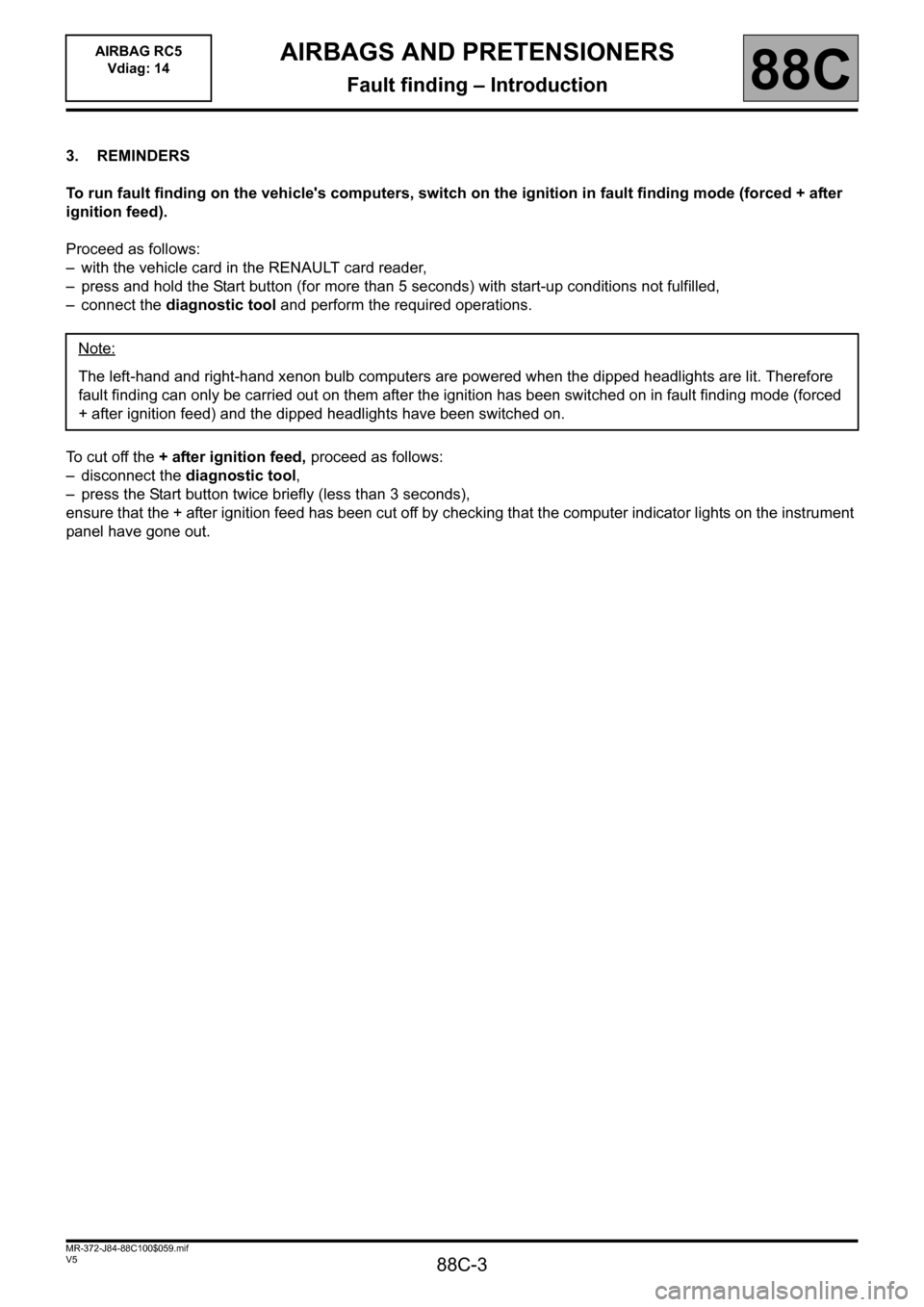
3. REMINDERS
To run fault finding on the vehicle's computers, switch on the ignition in fault finding mode (forced + after
ignition feed).
Proceed as follows:
– with the vehicle card in the RENAULT card reader,
– press and hold the Start button (for more than 5 seconds) with start-up conditions not fulfilled,
– connect the diagnostic tool and perform the required operations.
To cut off the + after ignition feed, proceed as follows:
– disconnect the diagnostic tool,
– press the Start button twice briefly (less than 3 seconds),
ensure that the + after ignition feed has been cut off by checking that the computer indicator lights on the instrument
panel have gone out.Note:
The left-hand and right-hand xenon bulb computers are powered when the dipped headlights are lit. Therefore
fault finding can only be carried out on them after the ignition has been switched on in fault finding mode (forced
+ after ignition feed) and the dipped headlights have been switched on.
Page 4 of 88

88C-4
MR-372-J84-88C100$059.mif
V5
AIRBAG RC5
Vdiag: 14AIRBAGS AND PRETENSIONERS
Fault finding – Introduction88C
Faults
Faults are declared present or stored (depending on whether they appeared in a certain context and have
disappeared since, or whether they remain present but are not diagnosed within the current context).
The present or stored status of the faults should be taken into consideration when the diagnostic tool is used after
the + after ignition feed has been connected (with no action on the system components).
For a fault present, apply the procedure described in the section on the Interpretation of faults.
For a stored fault, note the faults displayed and apply the instructions in the Notes section.
If the fault is confirmed when the instructions in the Notes section are applied, the fault is present. Deal with
the fault.
If the fault is not confirmed, check:
– the electrical lines which correspond to the fault,
– the connectors for these lines (for oxidation, bent pins, etc.),
– the resistance of the component detected as defective,
– the condition of the wires (melted or cut insulation, wear),
– or use the fault finding procedure to check the circuit of the component at fault.
Conformity check
The aim of the conformity check is to check data that does not produce a fault on the diagnostic tool because
the data is inconsistent. Therefore, this stage is used to:
– run fault finding on faults that do not have a fault display, and which may correspond to a customer complaint,
– check that the system is operating correctly and that there is no risk of a fault recurring after repairs.
This section gives the fault finding procedures for statuses and parameters and the conditions for checking them.
If a status is not behaving normally or a parameter is outside the permitted tolerance values, consult the
corresponding fault finding page.
Customer complaints - Fault finding chart
If the test with the diagnostic tool is OK but the customer complaint is still present, the fault should be processed by
customer complaints.
A summary of the overall procedure to follow is provided on the following page in
the form of a flow chart
Page 5 of 88

88C-5
MR-372-J84-88C100$059.mif
V5
AIRBAG RC5
Vdiag: 14AIRBAGS AND PRETENSIONERS
Fault finding – Introduction88C
4. FAULT FINDING PROCEDURE
Check battery charge and condition
of the fuses
Print the system fault finding log
(available on CLIP and in
the Workshop Repair Manual
or Technical Note)
Connect CLIP
NO
Dialogue with
computer?
YES
Read the faults
NO
Faults present
YES
Deal with present faults
Deal with stored faults
NO
The cause is still
presentFault
solved
YES
See ALP no. 1
Conformity check
NO
The cause is still
presentFault
solved
YES
Use fault finding charts (ALPs)
NO
The cause is still
presentFault
solved
YES
Contact the Techline with the
completed fault finding log
Page 22 of 88

88C-22
MR-372-J84-88C100$413.mif
V5
AIRBAGS AND PRETENSIONERS
Fault finding – Interpretation of faults
AIRBAG RC5
Vdiag: 14
88C
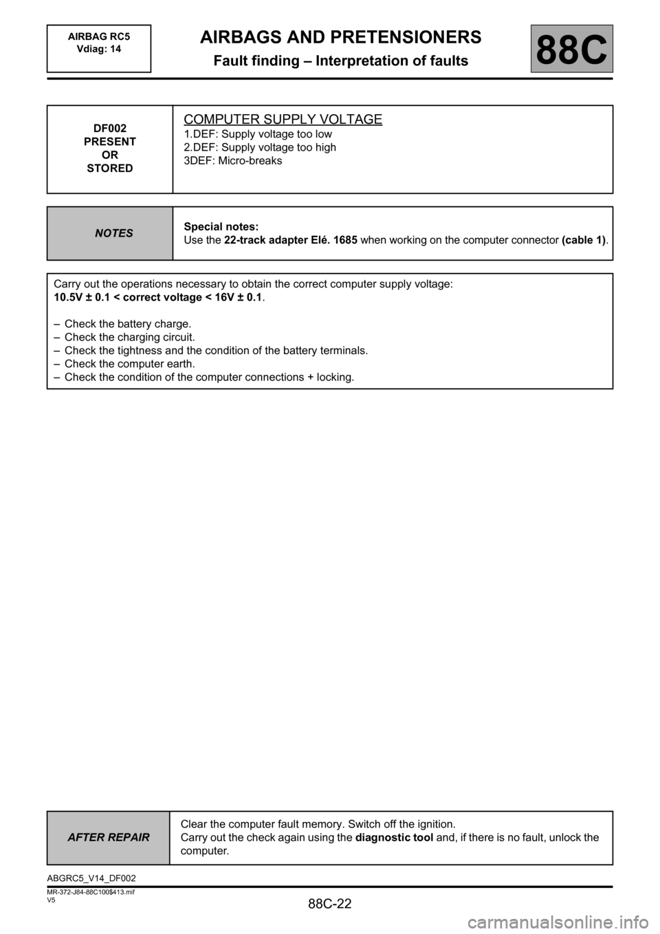
DF002
PRESENT
OR
STOREDCOMPUTER SUPPLY VOLTAGE
1.DEF: Supply voltage too low
2.DEF: Supply voltage too high
3DEF: Micro-breaks
NOTESSpecial notes: Use the 22-track adapter Elé. 1685 when working on the computer connector (cable 1).
Carry out the operations necessary to obtain the correct computer supply voltage:
10.5V ± 0.1 < correct voltage < 16V ± 0.1.
– Check the battery charge.
– Check the charging circuit.
– Check the tightness and the condition of the battery terminals.
– Check the computer earth.
– Check the condition of the computer connections + locking.
AFTER REPAIRClear the computer fault memory. Switch off the ignition.
Carry out the check again using the diagnostic tool and, if there is no fault, unlock the
computer.
ABGRC5_V14_DF002
Page 26 of 88

88C-26
MR-372-J84-88C100$413.mif
V5
AIRBAGS AND PRETENSIONERS
Fault finding – Interpretation of faults
AIRBAG RC5
Vdiag: 14
88C
DF038
PRESENT
OR
STOREDDRIVER'S SIDE SENSOR
CO : Open circuit
CC.0 : Short circuit to earth
1.DEF : Configuration
2.DEF : Sensor internal electronic fault
NOTESSpecial notes:
Use the 64-track adapter Elé. 1717 when working on the computer connector.
CC.0
CO
NOTESNone.
Lock the computer using the diagnostic tool.
Check that the driver's side sensor is connected correctly and check its connections.
Check the condition of the computer connections (tracks 27 and 28).
Check the condition of the 64-track connector (locking system, connections, etc.).
Check the continuity and insulation of the connections between:
– Bornier Elé. 1717 terminal 27
– Bornier Elé. 1717 terminal 28track 1 sensor connector
track 2 sensor connector
AFTER REPAIRClear the computer fault memory. Switch off the ignition.
Carry out the check again using the diagnostic tool and, if there is no fault, unlock the
computer.
ABGRC5_V14_DF038
Page 28 of 88

88C-28
MR-372-J84-88C100$413.mif
V5
AIRBAGS AND PRETENSIONERS
Fault finding – Interpretation of faults
AIRBAG RC5
Vdiag: 14
88C
DF043
PRESENT
OR
STOREDPASSENGER SIDE SENSOR
CO : Open circuit
CC.0 : Short circuit to earth
1.DEF : Configuration
2.DEF : Sensor internal electronic fault
NOTESSpecial notes:
Use the 64-track adapter Elé. 1717 when working on the computer connector.
CC.0 /CO
NOTESNone.
Lock the computer using the diagnostic tool.
Check that the driver's side sensor is connected correctly and check its connections.
Check the condition of the computer connections (tracks 61 and 62).
Check the condition of the 64-track connector (locking system, connections, etc.).
Check the continuity and insulation of the connections between:
Bornier Elé. 1717 terminal 61
Bornier Elé. 1717 terminal 62track 1 sensor connector
track 2 sensor connector
AFTER REPAIRClear the computer fault memory. Switch off the ignition.
Carry out the check again using the diagnostic tool and, if there is no fault, unlock the
computer.
ABGRC5_V14_DF043
Page 43 of 88

88C-43
MR-372-J84-88C100$413.mif
V5
AIRBAGS AND PRETENSIONERS
Fault finding – Interpretation of faults
AIRBAG RC5
Vdiag: 14
88C
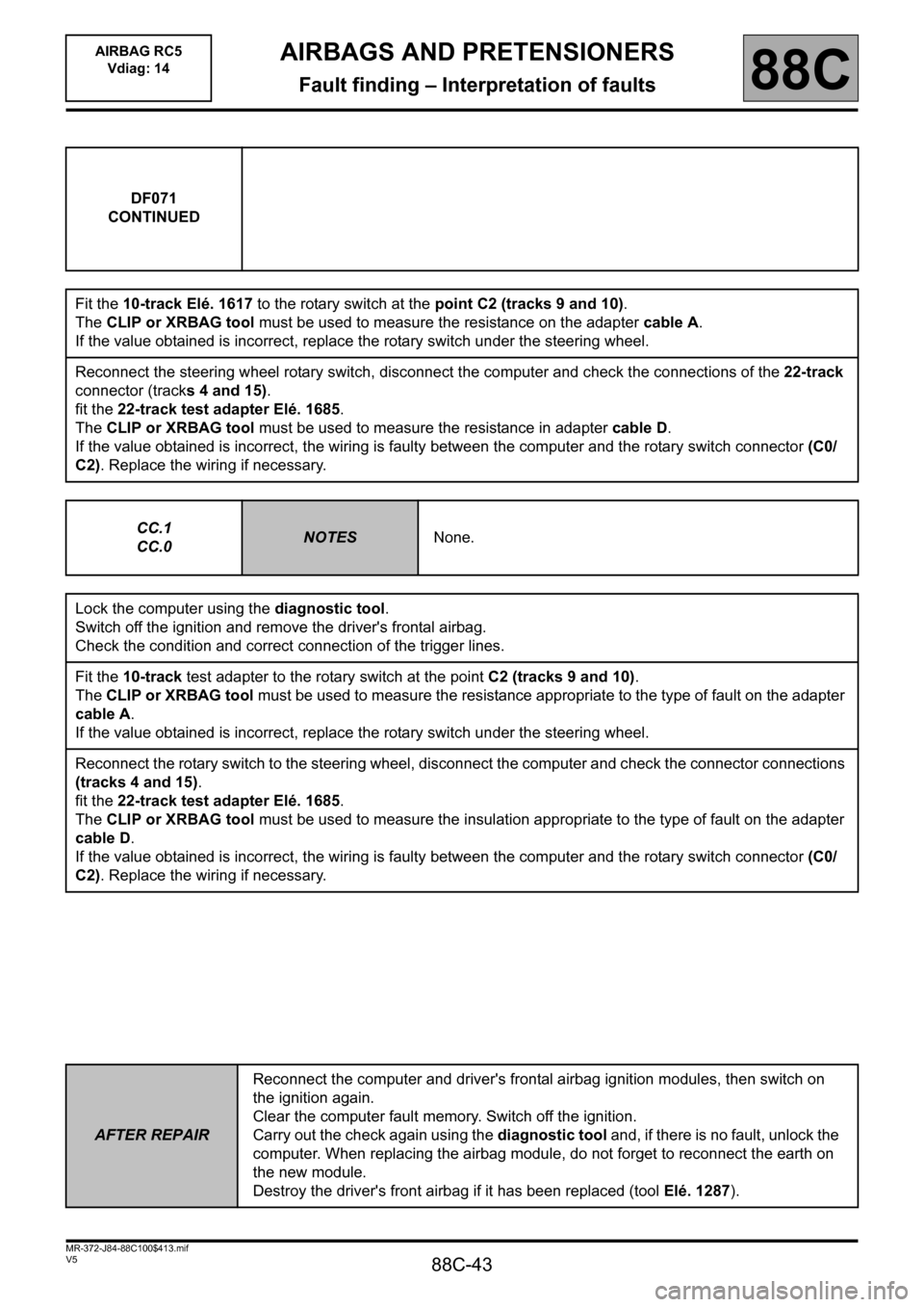
DF071
CONTINUED
Fit the 10-track Elé. 1617 to the rotary switch at the point C2 (tracks 9 and 10).
The CLIP or XRBAG tool must be used to measure the resistance on the adapter cable A.
If the value obtained is incorrect, replace the rotary switch under the steering wheel.
Reconnect the steering wheel rotary switch, disconnect the computer and check the connections of the 22-track
connector (tracks 4 and 15).
fit the 22-track test adapter Elé. 1685.
The CLIP or XRBAG tool must be used to measure the resistance in adapter cable D.
If the value obtained is incorrect, the wiring is faulty between the computer and the rotary switch connector (C0/
C2). Replace the wiring if necessary.
CC.1
CC.0
NOTESNone.
Lock the computer using the diagnostic tool.
Switch off the ignition and remove the driver's frontal airbag.
Check the condition and correct connection of the trigger lines.
Fit the 10-track test adapter to the rotary switch at the point C2 (tracks 9 and 10).
The CLIP or XRBAG tool must be used to measure the resistance appropriate to the type of fault on the adapter
cable A.
If the value obtained is incorrect, replace the rotary switch under the steering wheel.
Reconnect the rotary switch to the steering wheel, disconnect the computer and check the connector connections
(tracks 4 and 15).
fit the 22-track test adapter Elé. 1685.
The CLIP or XRBAG tool must be used to measure the insulation appropriate to the type of fault on the adapter
cable D.
If the value obtained is incorrect, the wiring is faulty between the computer and the rotary switch connector (C0/
C2). Replace the wiring if necessary.
AFTER REPAIRReconnect the computer and driver's frontal airbag ignition modules, then switch on
the ignition again.
Clear the computer fault memory. Switch off the ignition.
Carry out the check again using the diagnostic tool and, if there is no fault, unlock the
computer. When replacing the airbag module, do not forget to reconnect the earth on
the new module.
Destroy the driver's front airbag if it has been replaced (tool Elé. 1287).
Page 45 of 88

88C-45
MR-372-J84-88C100$413.mif
V5
AIRBAGS AND PRETENSIONERS
Fault finding – Interpretation of faults
AIRBAG RC5
Vdiag: 14
88C
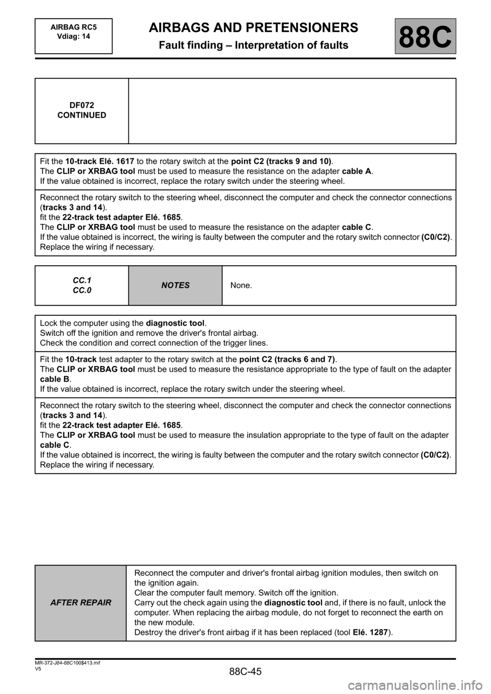
DF072
CONTINUED
Fit the 10-track Elé. 1617 to the rotary switch at the point C2 (tracks 9 and 10).
The CLIP or XRBAG tool must be used to measure the resistance on the adapter cable A.
If the value obtained is incorrect, replace the rotary switch under the steering wheel.
Reconnect the rotary switch to the steering wheel, disconnect the computer and check the connector connections
(tracks 3 and 14).
fit the 22-track test adapter Elé. 1685.
The CLIP or XRBAG tool must be used to measure the resistance on the adapter cable C.
If the value obtained is incorrect, the wiring is faulty between the computer and the rotary switch connector (C0/C2).
Replace the wiring if necessary.
CC.1
CC.0NOTESNone.
Lock the computer using the diagnostic tool.
Switch off the ignition and remove the driver's frontal airbag.
Check the condition and correct connection of the trigger lines.
Fit the 10-track test adapter to the rotary switch at the point C2 (tracks 6 and 7).
The CLIP or XRBAG tool must be used to measure the resistance appropriate to the type of fault on the adapter
cable B.
If the value obtained is incorrect, replace the rotary switch under the steering wheel.
Reconnect the rotary switch to the steering wheel, disconnect the computer and check the connector connections
(tracks 3 and 14).
fit the 22-track test adapter Elé. 1685.
The CLIP or XRBAG tool must be used to measure the insulation appropriate to the type of fault on the adapter
cable C.
If the value obtained is incorrect, the wiring is faulty between the computer and the rotary switch connector (C0/C2).
Replace the wiring if necessary.
AFTER REPAIRReconnect the computer and driver's frontal airbag ignition modules, then switch on
the ignition again.
Clear the computer fault memory. Switch off the ignition.
Carry out the check again using the diagnostic tool and, if there is no fault, unlock the
computer. When replacing the airbag module, do not forget to reconnect the earth on
the new module.
Destroy the driver's front airbag if it has been replaced (tool Elé. 1287).