Page 44 of 68

AIRBAG - SEAT BELT PRETENSIONERS
Fault finding - Interpretation of faults
88C-44
88C
V3 MR-372-J84-88C000$071.mif
AIRBAG ACU4
VDIAG No.: 04
DF072
CONTINUED
CC.1 - CC.0
NOTESNone.
Lock the computer using the command on the diagnostic tool.
Switch off the ignition and unclip the driver's frontal airbag.
Check the condition and correct connection of the trigger lines.
Fit the 10-track test adapter (Elé. 1617) to the rotary switch at point C2 (tracks 6 and 7).
The CLIP or XRBAG tool must be used to measure the appropriate insulation for the type of fault on cable B
(driver's front airbag connected).
If the value obtained is incorrect, replace the rotary switch beneath the steering wheel.
Reconnect the rotary switch under the steering wheel, disconnect the computer and check the connector
connections (tracks 3 and 14).
Fit the 22-track test adapter (Elé. 1685).
The CLIP or XRBAG tool must be used to measure the appropriate insulation for the type of fault on adapter
cable C.
If the value obtained is incorrect, the wiring is faulty between the computer and the rotary switch connector
(C0/C2). Replace the wiring if necessary.
AFTER REPAIRReconnect the computer and driver's frontal airbag ignition modules, then switch on the
ignition again.
Clear the computer memory then switch off the ignition.
Carry out the check again using the diagnostic tool and, if there are no faults, unlock
the computer. When replacing the airbag module, do not forget to reconnect the earth
on the new one.
Destroy the driver's front airbag if it has been replaced (tool Elé. 1287).
ACU4 Vdiag04 J84 1.0
Page 51 of 68

AIRBAG - SEAT BELT PRETENSIONERS
Fault finding - Fault Interpretation
88C - 51
88C
V3 MR-372-J84-88C000$072.mif
AIRBAG ACU4
Vdiag: 04
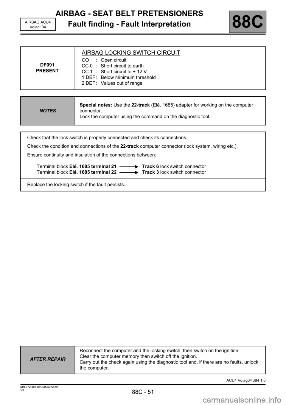
DF091
PRESENT
AIRBAG LOCKING SWITCH CIRCUIT
CO : Open circuit
CC.0 : Short circuit to earth
CC.1 : Short circuit to + 12 V
1.DEF : Below minimum threshold
2.DEF : Values out of range
NOTESSpecial notes: Use the 22-track (Elé. 1685) adapter for working on the computer
connector.
Lock the computer using the command on the diagnostic tool.
Check that the lock switch is properly connected and check its connections.
Check the condition and connections of the 22-track computer connector (lock system, wiring etc.).
Ensure continuity and insulation of the connections between:
Terminal block Elé. 1685 terminal 21 Track 6 lock switch connector
Terminal block Elé. 1685 terminal 22 Track 3 lock switch connector
Replace the locking switch if the fault persists.
AFTER REPAIRReconnect the computer and the locking switch, then switch on the ignition.
Clear the computer memory then switch off the ignition.
Carry out the check again using the diagnostic tool and, if there are no faults, unlock
the computer.
ACU4 Vdiag04 J84 1.0
Page 59 of 68

AIRBAG - SEAT BELT PRETENSIONERS
Fault finding - Fault Interpretation
88C - 59
88C
V3 MR-372-J84-88C000$072.mif
AIRBAG ACU4
Vdiag: 04
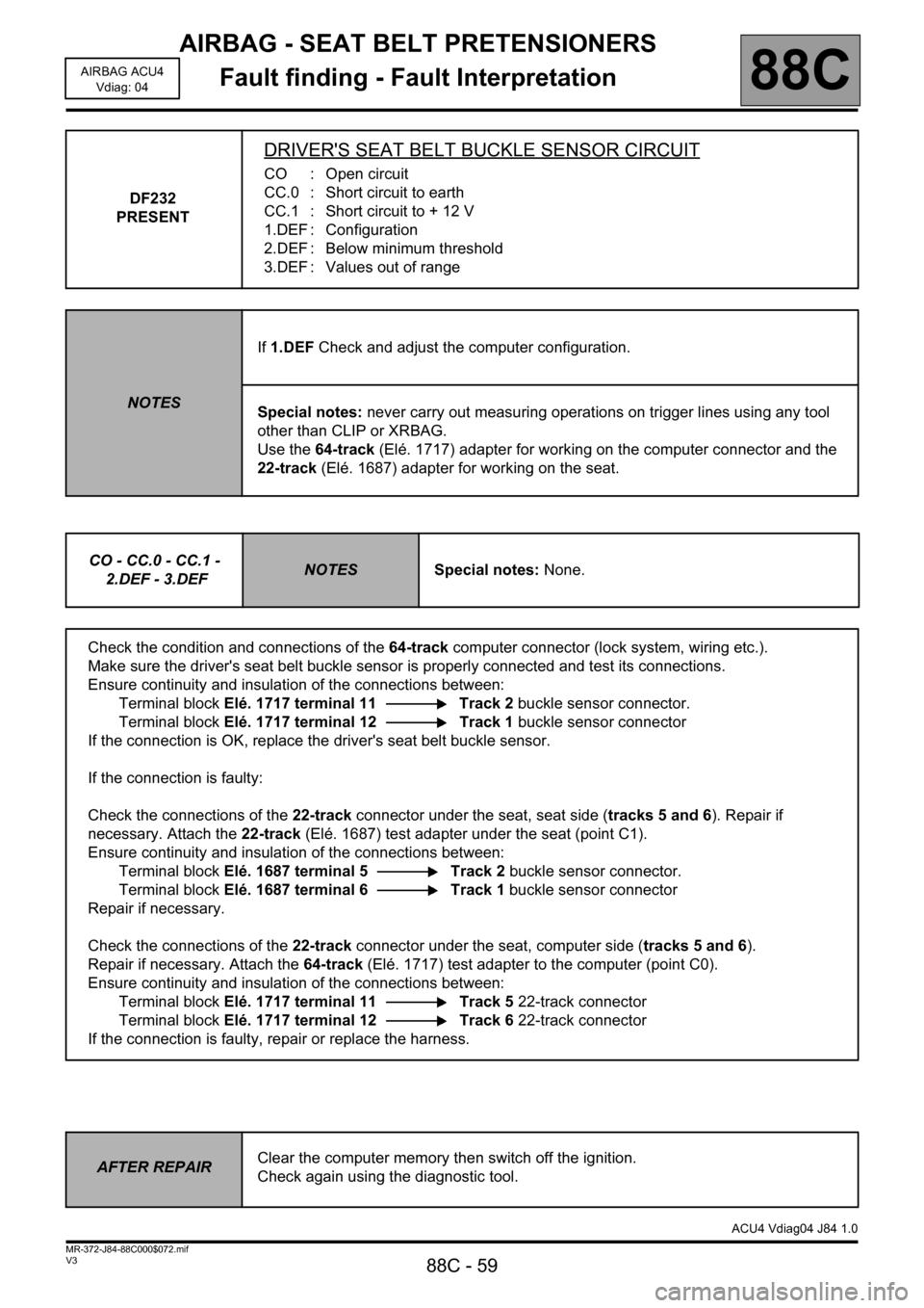
DF232
PRESENT
DRIVER'S SEAT BELT BUCKLE SENSOR CIRCUIT
CO : Open circuit
CC.0 : Short circuit to earth
CC.1 : Short circuit to + 12 V
1.DEF : Configuration
2.DEF : Below minimum threshold
3.DEF : Values out of range
NOTESIf 1.DEF Check and adjust the computer configuration.
Special notes: never carry out measuring operations on trigger lines using any tool
other than CLIP or XRBAG.
Use the 64-track (Elé. 1717) adapter for working on the computer connector and the
22-track (Elé. 1687) adapter for working on the seat.
CO - CC.0 - CC.1 -
2.DEF - 3.DEF
NOTESSpecial notes: None.
Check the condition and connections of the 64-track computer connector (lock system, wiring etc.).
Make sure the driver's seat belt buckle sensor is properly connected and test its connections.
Ensure continuity and insulation of the connections between:
Terminal block Elé. 1717 terminal 11 Track 2 buckle sensor connector.
Terminal block Elé. 1717 terminal 12 Track 1 buckle sensor connector
If the connection is OK, replace the driver's seat belt buckle sensor.
If the connection is faulty:
Check the connections of the 22-track connector under the seat, seat side (tracks 5 and 6). Repair if
necessary. Attach the 22-track (Elé. 1687) test adapter under the seat (point C1).
Ensure continuity and insulation of the connections between:
Terminal block Elé. 1687 terminal 5 Track 2 buckle sensor connector.
Terminal block Elé. 1687 terminal 6 Track 1 buckle sensor connector
Repair if necessary.
Check the connections of the 22-track connector under the seat, computer side (tracks 5 and 6).
Repair if necessary. Attach the 64-track (Elé. 1717) test adapter to the computer (point C0).
Ensure continuity and insulation of the connections between:
Terminal block Elé. 1717 terminal 11 Track 5 22-track connector
Terminal block Elé. 1717 terminal 12 Track 6 22-track connector
If the connection is faulty, repair or replace the harness.
AFTER REPAIRClear the computer memory then switch off the ignition.
Check again using the diagnostic tool.
ACU4 Vdiag04 J84 1.0
Page 68 of 68

AIRBAG - SEAT BELT PRETENSIONERS
Fault finding - Fault finding chart
88C - 68
88C
V3 MR-372-J84-88C000$100.mif
AIRBAG ACU4
Vdiag: 04
AIRBAG - SEAT BELT PRETENSIONERS
Fault finding - Fault finding chart
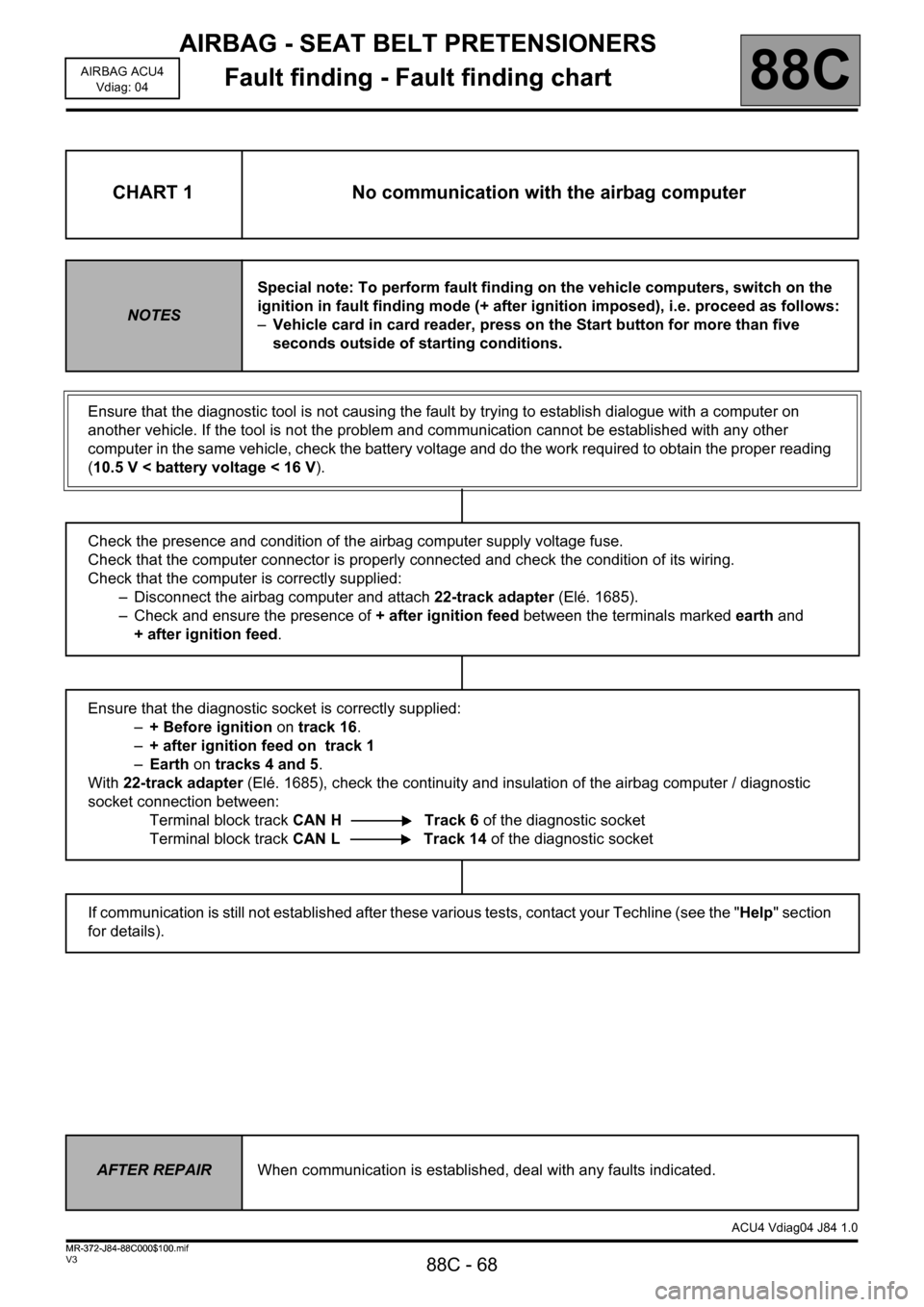
CHART 1 No communication with the airbag computer
NOTESSpecial note: To perform fault finding on the vehicle computers, switch on the
ignition in fault finding mode (+ after ignition imposed), i.e. proceed as follows:
–Vehicle card in card reader, press on the Start button for more than five
seconds outside of starting conditions.
Ensure that the diagnostic tool is not causing the fault by trying to establish dialogue with a computer on
another vehicle. If the tool is not the problem and communication cannot be established with any other
computer in the same vehicle, check the battery voltage and do the work required to obtain the proper reading
(10.5 V < battery voltage < 16 V).
Check the presence and condition of the airbag computer supply voltage fuse.
Check that the computer connector is properly connected and check the condition of its wiring.
Check that the computer is correctly supplied:
– Disconnect the airbag computer and attach 22-track adapter (Elé. 1685).
– Check and ensure the presence of + after ignition feed between the terminals marked earth and
+ after ignition feed.
Ensure that the diagnostic socket is correctly supplied:
–+ Before ignition on track 16.
–+ after ignition feed on track 1
–Earth on tracks 4 and 5.
With 22-track adapter (Elé. 1685), check the continuity and insulation of the airbag computer / diagnostic
socket connection between:
Terminal block track CAN H Track 6 of the diagnostic socket
Terminal block track CAN L Track 14 of the diagnostic socket
If communication is still not established after these various tests, contact your Techline (see the "Help" section
for details).
AFTER REPAIRWhen communication is established, deal with any faults indicated.
ACU4 Vdiag04 J84 1.0
MR-372-J84-88C000$100.mif