Page 5 of 232

3
Contents
CONTENT
S
9. TECHNOLOGY on
BOARD
5. ACCESSORIES
127-130
6. CHECKS
131-140
7. QUICK HELP
141-159
Emergency or assistance 9.1
Peugeot Connect
Navigation 9.3
Bluetooth telephone 9.23
Peugeot Connect Sound 9.35
Peugeot Connect USB 9.42
Bluetooth 9.45 Towing a trailer 127
Other accessories 129
Opening the bonnet 132
Petrol engine 133
Diesel engine 134
Levels 135
Checks 137
Fuel 139
Circuit disarmed 140
Diesel repriming pump 140Battery 141
Puncture repair kit 142
Changing a wheel 143
Removable
snow screen 147
Changing a bulb 148
a fuse 153
a windscreen wiper
blade 157
Being towed 158
8. TECHNICAL
DATA 160-166
Dimensions 160
Weights 164
Identifi cation features 165
10. VISUAL SEARCH
167-172
Exterior 167
Instruments and
controls 168
Interior 170
Technical data -
Maintenance 171
Peugeot Connect: Peugeot
Connect is the name given
to all of the new equipment
of the radio/navigation
range. The "In-Car Technology"
section presents the new
radio/navigation equipment.
The "Location" section
assists you in fi nding the
controls and functions
and their associated page
numbers on the schematic
outlines of the vehicle
(visual index).
Page 39 of 232

37
READY TO SET OFF
22
Instruments and controls
SERVICE INDICATOR
This programmes service intervals
according to the use of the vehicle.
More than 1 000 miles/km before
the next service is due
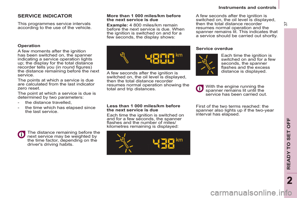
Example: 4 800 miles/km remain
before the next service is due. When
the ignition is switched on and for a
few seconds, the display shows:
A few seconds after the ignition is
switched on, the oil level is displayed,
then the total distance recorder
resumes normal operation showing the
total and trip distances.
Less than 1 000 miles/km before
the next service is due
Each time the ignition is switched on
and for a few seconds, the spanner
fl ashes and the number of miles/
kilometres remaining is displayed: A few seconds after the ignition is
switched on, the oil level is displayed,
then the total distance recorder
resumes normal operation and the
spanner remains lit. This indicates that
a service should be carried out shortly.
Service overdue
First of the two terms reached: the
spanner also lights up if the two-year
interval has elapsed.
Operation
A few moments after the ignition
has been switched on, the spanner
indicating a service operation lights
up; the display for the total distance
recorder tells you (in round fi gures)
the distance remaining before the next
service.
The points at which a service is due
are calculated from the last indicator
zero reset.
The point at which a service is due is
determined by two parameters:
- the distance travelled,
- the time which has elapsed since
the last service.
The distance remaining before the
next service may be weighted by
the time factor, depending on the
driver's driving habits. With the engine running the
spanner remains lit until the
service has been carried out. Each time the ignition is
switched on and for a few
seconds, the spanner
fl ashes and the excess
distance is displayed.
Page 67 of 232
65
EASE OF USE
andCOMFOR
T
3
Seats
FRONT SEATS
The following adjustments are
available:
1 - Forwards/backwards adjustment
Lift the bar and slide the seat forwards
or backwards.
3 - Driver's seat height adjustment
To raise the seat, pull the control
upwards then take your weight off the
seat cushion.
To lower the seat, pull the control
upwards then push on the seat
cushion.
2 - Seat back angle adjustment
With your back pressed against the
seat back, move the lever forwards
and set the required angle.
Page 85 of 232

83
EASE OF USE
andCOMFOR
T
3
Practical information
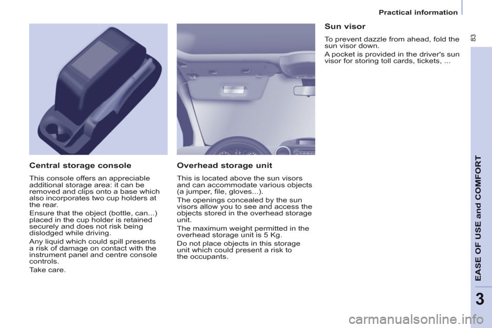
Overhead storage unit
This is located above the sun visors
and can accommodate various objects
(a jumper, fi le, gloves...).
The openings concealed by the sun
visors allow you to see and access the
objects stored in the overhead storage
unit.
The maximum weight permitted in the
overhead storage unit is 5 Kg.
Do not place objects in this storage
unit which could present a risk to
the occupants.
Central storage console
This console offers an appreciable
additional storage area: it can be
removed and clips onto a base which
also incorporates two cup holders at
the rear.
Ensure that the object (bottle, can...)
placed in the cup holder is retained
securely and does not risk being
dislodged while driving.
Any liquid which could spill presents
a risk of damage on contact with the
instrument panel and centre console
controls.
Take care.
Sun visor
To prevent dazzle from ahead, fold the
sun visor down.
A pocket is provided in the driver's sun
visor for storing toll cards, tickets, ...
Page 88 of 232
86
Practical information
ZENITH ROOF
The multifunction roof extends the
overhead storage unit. It consists of
the following components:
Storage compartments
Storage compartments are provided
on each side of the roof. The maximum
weight is 6 Kg.
The translucent base assists with
fi nding objects stored inside.
Do not store objects which could
present a risk to the occupants.
Courtesy lamp
The operation of the courtesy lamp is
identical to that of the front courtesy lamp.
Refer to the "Comfort and Safety"
section of chapter 3, "Courtesy
lamps" part.
Page 89 of 232
87
EASE OF USE
andCOMFOR
T
3
Practical information
From inside
From outside
Rear box
This roof box can be accessed from
the rear seats and the boot.
From the rear seats, slide the fl aps to
open.
Vents
A 3-position control allows you to
adjust the air fl ow through the vents.
The vents are also fi tted with a scented
air freshener. From the boot, place your thumb
on the recess then pull the handle
to open.
Open carefully to prevent objects
stored in this interior roof box from
falling out.
The maximum authorised weight is
10 Kg.
Page 92 of 232
90
Practical information
Zenith roof BARS
These two longitudinal Zenith roof bars
can be removed. The maximum authorised weight on
each bar is 35 kg.
In all cases, the load must rest on
the non-slip bands provided for this
purpose and must not touch the roof or
the glazing of the roof.
Recommendations for loading on
the roof:
- Open the protective covers.
- Use the screwdriver (stored in the
tool kit under the right-hand seat) to
remove the 4 bolts.
- Turn the bars 90° placing the
hollow parts towards the front.
- Tighten the 4 bolts.
- Close the protective covers.
- Use the strap passages A only to
secure the load fi rmly.
Page 93 of 232
91
EASE OF USE
andCOMFOR
T
3
Practical information
ROOF BARS
If you install transverse bars on these bars, refer to the weight values indicated
by the manufacturer but do not exceed 75 Kg.