Page 14 of 407
1. Battery (P. 8-13)
2. Fuse/fusible link box (P. 8-20)
3. Transmission dipstick (P. 8-11)
4. Engine oil filler cap (P. 8-8)
5. Brake fluid reservoir (P. 8-12)
6. Window washer fluid reservoir (P. 8-12)
7. Air cleaner (P. 8-17)
8. Drive belt location (P. 8-15)
9. Radiator cap (P. 8-7)
10. Power steering fluid reservoir (P. 8-11)
11. Engine oil dipstick (P. 8-8)
12. Engine coolant reservoir (P. 8-7)
NOTE:
Engine cover removed for clarity.
See the page number indicated in paren-
theses for operating details.
Page 95 of 407
WARNING
●Your brake system may not be working
properly if the warning light is on. Driv-
ing could be dangerous. If you judge it
to be safe, drive carefully to the nearest
service station for repairs. Otherwise,
have your vehicle towed because driv-
ing it could be dangerous.
● Pressing the brake pedal with the en-
gine stopped and/or a low brake fluid
level may increase your stopping dis-
tance and braking will require greater
pedal effort as well as pedal travel.
● If the brake fluid level is below the
MINIMUM or MIN mark on the brake
fluid reservoir, do not drive until the
brake system has been checked at a
NISSAN dealer.
Page 103 of 407
Vehicle information display warnings
and indicators
1. Door open warning
2. Low fuel warning
3. Low windshield washer fluid warning4. Parking brake warning
5. Cruise main switch indicator (if so
equipped)
6. Cruise set switch indicator (if so equipped) 7. Transfer 4LO position indicator (
Page 104 of 407

Door open warning
This warning illuminates when a door has been
opened and the engine is running.
Low fuel warning
This warning illuminates when the fuel level in the
fuel tank is getting low. Refuel as soon as it is
convenient, preferably before the fuel gauge
reaches E (Empty) .There will be a small re-
serve of fuel in the tank when the fuel
gauge needle reaches E (Empty) .
Low windshield washer fluid warning
This warning illuminates when the windshield
washer fluid is at a low level. Add windshield
washer fluid as necessary. See “Window washer
fluid” in the “Maintenance and do-it-yourself”
section of this manual.
Parking brake warning
This warning illuminates when the parking brake
is set and the vehicle is driven.
Cruise main switch indicator (if so
equipped)
This indicator illuminates when the cruise control
main switch is pushed. The indicator turns off
when the main switch is pushed again. When the
cruise main switch indicator illuminates, the
cruise control system is operational. Cruise set switch indicator (if so equipped)
This indicator illuminates while the vehicle speed
is controlled by the cruise control system. If the
indicator blinks while the engine is running, it may
indicate the cruise control system is not function-
ing properly. Have the system checked by a
NISSAN dealer.
Transfer 4LO position indicator (
Page 112 of 407
If the parking brake is applied before the engine is
started, the daytime running lights do not illumi-
nate. The daytime running lights illuminate when
the parking brake is released. The daytime run-
ning lights will remain on until the ignition switch
is placed in the OFF position.
Page 116 of 407
When the E-Lock switch is turned ON, the indi-
cator light will flash until the system engages.
However, if all operation conditions listed above
are not met or the system becomes disengaged,
the indicator light will continue to flash.
The Anti-Lock Brake (ABS) system is disabled
and the ABS light illuminates when the E-Lock
system is ON. Also, the Vehicle Dynamic Control
(VDC) system is disabled and the VDC light
illuminates when the E-Lock system is ON.
See “Electronic locking rear differential (E-Lock)
system” in the “Starting and Driving” section for
further explanation and system limitations.
Page 162 of 407

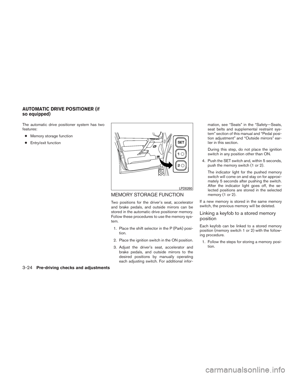
The automatic drive positioner system has two
features:● Memory storage function
● Entry/exit function
MEMORY STORAGE FUNCTION
Two positions for the driver’s seat, accelerator
and brake pedals, and outside mirrors can be
stored in the automatic drive positioner memory.
Follow these procedures to use the memory sys-
tem.
1. Place the shift selector in the P (Park) posi- tion.
2. Place the ignition switch in the ON position.
3. Adjust the driver’s seat, accelerator and brake pedals, and outside mirrors to the
desired positions by manually operating
each adjusting switch. For additional infor- mation, see “Seats” in the “Safety—Seats,
seat belts and supplemental restraint sys-
tem” section of this manual and “Pedal posi-
tion adjustment” and “Outside mirrors” ear-
lier in this section.
During this step, do not place the ignition
switch in any position other than ON.
4. Push the SET switch and, within 5 seconds, push the memory switch (1 or 2) .
The indicator light for the pushed memory
switch will come on and stay on for approxi-
mately 5 seconds after pushing the switch.
After the indicator light goes off, the se-
lected positions are stored in the selected
memory (1 or 2) .
If a new memory is stored in the same memory
switch, the previous memory will be deleted.
Linking a keyfob to a stored memory
position
Each keyfob can be linked to a stored memory
position (memory switch 1 or 2) with the follow-
ing procedure. 1. Follow the steps for storing a memory posi- tion.
Page 245 of 407
SPEAKER ADAPTATION (SA) MODE
Speaker Adaptation allows up to two out-of-
dialect users to train the system to improve rec-
ognition accuracy. By repeating a number of
commands, the users can create a voice model of
their own voice that is stored in the system. The
system is capable of storing a different speaker
adaptation model for memory A and memory B.
If memory A is available, the system will use
memory A to store the model. If memory A is in
use and memory B is available, the system will
use memory B to store the model. If both of the
memory locations are in use, the system will ask
the user to select which memory location should
be overwritten.
Training procedure
The procedure for training a voice is as follows.1. Position the vehicle in a reasonably quiet outdoor location.
2. Sit in the driver’s seat with the engine run- ning, the parking brake on, and the transmis-
sion in P (Park) .
3. Press and hold the