2011 NISSAN TIIDA high
[x] Cancel search: highPage 21 of 3787

AT-4
Transmission Range Switch ..................................225
Output Speed Sensor ............................................227
Input Speed Sensor ...............................................228
Differential Side Oil Seal ........................................229
AIR BREATHER HOSE ...................................232
Removal and Installation ..................................... ..232
TRANSAXLE ASSEMBLY ..............................233
Removal and Installation ..................................... ..233
OVERHAUL .................................................... .237
Component .......................................................... ..237
Oil Channel ............................................................250
Location of Adjusting Shims, Needle Bearings and
Thrust Washers .....................................................
253
Location of Snap Rings .........................................255
DISASSEMBLY .............................................. .257
Disassembly ........................................................ ..257
REPAIR FOR COMPONENT PARTS ..............275
Manual Shaft ....................................................... ..275
Oil Pump ................................................................278
Control Valve Assembly ........................................281
Control Valve Upper Body .....................................290
Control Valve Lower Body ................................... ..294
Reverse Clutch ......................................................297
High Clutch ............................................................302
Forward and Overrun Clutches .............................307
Low & Reverse Brake ............................................314
Rear Internal Gear and Forward Clutch Hub .........318
Output Shaft, Output Gear, Idler Gear, Reduction
Pinion Gear and Bearing Retainer .........................
322
Band Servo Piston Assembly ................................331
Final Drive .............................................................337
ASSEMBLY .....................................................344
Assembly (1) ........................................................ ..344
Adjustment (1) (For HR16DE Engine Models) ..... .345
Adjustment (1) (For MR18DE Engine Models) .....349
Assembly (2) .........................................................355
Adjustment (2) .......................................................360
Assembly (3) .........................................................363
SERVICE DATA AND SPECIFICATIONS
(SDS) ................................................................
373
General Specification ........................................... .373
Vehicle Speed at Which Gear Shifting Occurs .....373
Vehicle Speed at When Lock-up Occurs/Releases
.
373
Stall Speed ............................................................374
Line Pressure ........................................................374
Adjusting shims, Needle Bearings, Thrust Wash-
ers and Snap Rings ..............................................
374
Control Valves .......................................................375
Accumulator ..........................................................376
Clutches and Brakes .............................................376
Final Drive .............................................................378
Planetary Carrier ...................................................378
Oil Pump ...............................................................378
Input Shaft .............................................................378
Reduction Pinion Gear ..........................................378
Band Servo ...........................................................378
Output Shaft ..........................................................379
Bearing Retainer ...................................................379
Total End Play ...................................................... .379
Reverse Clutch End Play ......................................379
Removal and Installation .......................................379
Shift Solenoid Valves ........................................... .379
Solenoid Valves ....................................................380
A/T Fluid Temperature Sensor ..............................380
Output Speed Sensor ...........................................380
Dropping Resistor .................................................380
Input Speed Sensor ..............................................380
Revision: May 2010 2011 Versa
Page 26 of 3787
PRECAUTIONSAT-9
< SERVICE INFORMATION >
DE
F
G H
I
J
K L
M A
B
AT
N
O P
• Gaskets, seals and O-rings should be replaced any time the A/T is disassembled.
• It is very important to perform func tional tests whenever they are indicated.
• The valve body contains precision parts and requires extreme care when parts are removed and serviced.
Place disassembled valve body parts in order for easier and proper assembly. Care will also prevent springs
and small parts from becoming scattered or lost.
• Properly installed valves, sleeves, plugs, etc. will slide along bores in valve body under their own weight.
• Before assembly, apply a coat of recommended ATF to all parts. Apply petroleum jelly to protect O-rings and seals, or hold bearings and washers in pl ace during assembly. Do not use grease.
• Extreme care should be taken to avoid damage to O-rings, seals and gaskets when assembling.
• Clean or replace ATF cooler if excessive foreign material is found in oil pan or clogging strainer. Refer to AT-
18, "A/T Fluid Cooler Cleaning".
• After overhaul, refill the A/T with new ATF.
• When the A/T drain plug is removed, only some of the fluid is drained. Old A/T fluid will remain in torque con- verter and ATF cooling system.
Always follow the procedures under “Changing A/T Fluid” in the AT section when changing A/T fluid. Refer to
AT-17, "
Changing A/T Fluid", AT-17, "Checking A/T Fluid".
Service Notice or PrecautionINFOID:0000000005928067
ATF COOLER SERVICE
If A/T fluid contains frictional material (clutches, bands, etc.), or if an A/T is repaired, overhauled, or replaced,
inspect and clean the A/T oil cooler mounted in the radiator or replace the radiator. Flush cooler lines using
cleaning solvent and compressed air after repair. Check Service Bulletins for latest A/T oil cooler cleaning pro-
cedure. For radiator replacement, refer to CO-16, "
Removal and Installation" (HR16DE engine models), CO-
40, "Removal and Installation" (MR18DE engine models).
TORQUE CONVERTER SERVICE
The torque converter should be replaced under any of the following conditions:
• External leaks in the hub weld area.
• Converter hub is scored or damaged.
• Converter pilot is broken, damaged or fits poorly into crankshaft.
• Steel particles are found after flushing the cooler and cooler lines.
• Pump is damaged or steel particles are found in the converter.
• Vehicle has TCC shudder and/or no TCC apply. Replace only after all hydraulic and electrical diagnoses
have been made. (Converter clutch material may be glazed.)
• Converter is contaminated with engi ne coolant containing antifreeze.
• Internal malfunction of stator roller clutch.
• Heavy clutch debris due to overheating (blue converter).
• Steel particles or clutch lining material found in flui d filter or on magnet when no internal parts in unit are
worn or damaged — indicates that lining material came from converter.
The torque converter should not be replaced if:
• The fluid has an odor, is discolored, and there is no evidence of metal or clutch facing particles.
• The threads in one or more of the converter bolt holes are damaged.
• A/T malfunction did not display evidence of damaged or worn internal parts, steel particles or clutch plate lin-
ing material in unit and inside the fluid filter.
• Vehicle has been exposed to high mileage (only). The e xception may be where the torque converter clutch
dampener plate lining has seen excess wear by vehicles operated in heavy and/or constant traffic, such as
taxi, delivery or police use.
OBD-II SELF-DIAGNOSIS
• A/T self-diagnosis is performed by the TCM in combination with the ECM. The results can be read through the blinking pattern of the OD OFF indicator lamp or the malfunction indicator lamp (MIL). Refer to the table
on AT-82, "
Diagnosis Procedure without CONSULT-III" for the indicator used to display each self-diagnostic
result.
• The self-diagnostic results indicated by the MIL are automatically stored in both the ECM and TCM memo- ries.
Always perform the procedure “HOW TO ERASE DTC” on AT-39, "
OBD-II Diagnostic Trouble Code
(DTC)" to complete the repair and avoid unnecessary blinking of the MIL.
• The following self-diagnostic items can be detected us ing ECM self-diagnostic results mode* only when the
OD OFF indicator lamp does not indicate any malfunctions.
- Transmission range switch
- A/T 1GR, 2GR, 3GR, or 4GR function
Revision: May 2010 2011 Versa
Page 35 of 3787
AT-18
< SERVICE INFORMATION >
A/T FLUID
5. Run engine at idle speed for 5 minutes.
6. Check A/T fluid level and condition. Refer to AT-17, "
Checking A/T Fluid".
A/T Fluid Cooler CleaningINFOID:0000000005928072
Whenever the A/T is repaired, overhauled, or replaced, the A/T fluid cooler mounted in the radiator must be
inspected and cleaned.
Metal debris and friction material, if present, can becom e trapped in the A/T fluid cooler. This debris can con-
taminate the newly serviced A/T or, in severe cases, can bloc k or restrict the flow of A/T fluid. In either case,
malfunction of the newly serviced A/T may result.
Debris, if present, may build up as A/T fluid enters the c ooler inlet. It will be necessary to back flush the cooler
through the cooler outlet in order to flush out any built up debris.
A/T FLUID COOLER CLEANING PROCEDURE
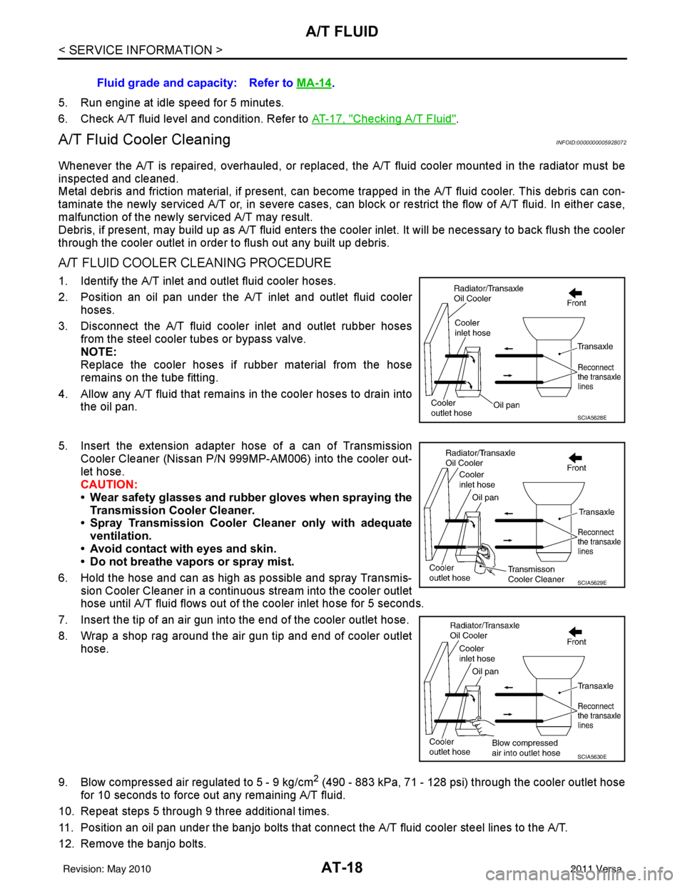
1. Identify the A/T inlet and outlet fluid cooler hoses.
2. Position an oil pan under the A/T inlet and outlet fluid cooler hoses.
3. Disconnect the A/T fluid cooler inlet and outlet rubber hoses from the steel cooler tubes or bypass valve.
NOTE:
Replace the cooler hoses if rubber material from the hose
remains on the tube fitting.
4. Allow any A/T fluid that remains in the cooler hoses to drain into the oil pan.
5. Insert the extension adapter hose of a can of Transmission
Cooler Cleaner (Nissan P/N 999MP-AM006) into the cooler out-
let hose.
CAUTION:
• Wear safety glasses and rubber gloves when spraying the Transmission Cooler Cleaner.
• Spray Transmission Cooler Cleaner only with adequate
ventilation.
• Avoid contact with eyes and skin.
• Do not breathe vapors or spray mist.
6. Hold the hose and can as high as possible and spray Transmis- sion Cooler Cleaner in a continuous stream into the cooler outlet
hose until A/T fluid flows out of t he cooler inlet hose for 5 seconds.
7. Insert the tip of an air gun into the end of the cooler outlet hose.
8. Wrap a shop rag around the air gun tip and end of cooler outlet hose.
9. Blow compressed air regulated to 5 - 9 kg/cm
2 (490 - 883 kPa, 71 - 128 psi) through the cooler outlet hose
for 10 seconds to force out any remaining A/T fluid.
10. Repeat steps 5 through 9 three additional times.
11. Position an oil pan under the banjo bolts that connec t the A/T fluid cooler steel lines to the A/T.
12. Remove the banjo bolts. Fluid grade and capacity: Refer to
MA-14
.
SCIA5628E
SCIA5629E
SCIA5630E
Revision: May 2010 2011 Versa
Page 36 of 3787
A/T FLUIDAT-19
< SERVICE INFORMATION >
DE
F
G H
I
J
K L
M A
B
AT
N
O P
13. Flush each steel line from the cooler side back toward the A/T by spraying Transmission Cooler Cleaner in a continuous stream for 5 seconds.
14. Blow compressed air regulated to 5 - 9 kg/cm
2 (490 - 883 kPa, 71 - 128 psi) through each steel line from
the cooler side back toward the A/T for 10 seconds to force out any remaining A/T fluid.
15. Ensure all debris is removed from the steel cooler lines.
16. Ensure all debris is removed from the banjo bolts and fittings.
17. Perform "A/T FLUID COOL ER DIAGNOSIS PROCEDURE".
A/T FLUID COOLER DIAGNOSIS PROCEDURE
NOTE:
Insufficient cleaning of the cooler inlet hose exte rior may lead to inaccurate debris identification.
1. Position an oil pan under the A/T inlet and outlet cooler hoses.
2. Clean the exterior and tip of the cooler inlet hose.
3. Insert the extension adapter hose of a can of Transmission Cooler Cleaner (Nissan P/N 999MP-AM006) into the cooler out-
let hose.
CAUTION:
• Wear safety glasses and rubber gloves when spraying the
Transmission Cooler Cleaner.
• Spray Transmission Cooler Cleaner only with adequate
ventilation.
• Avoid contact with eyes and skin.
• Do not breathe vapors or spray mist.
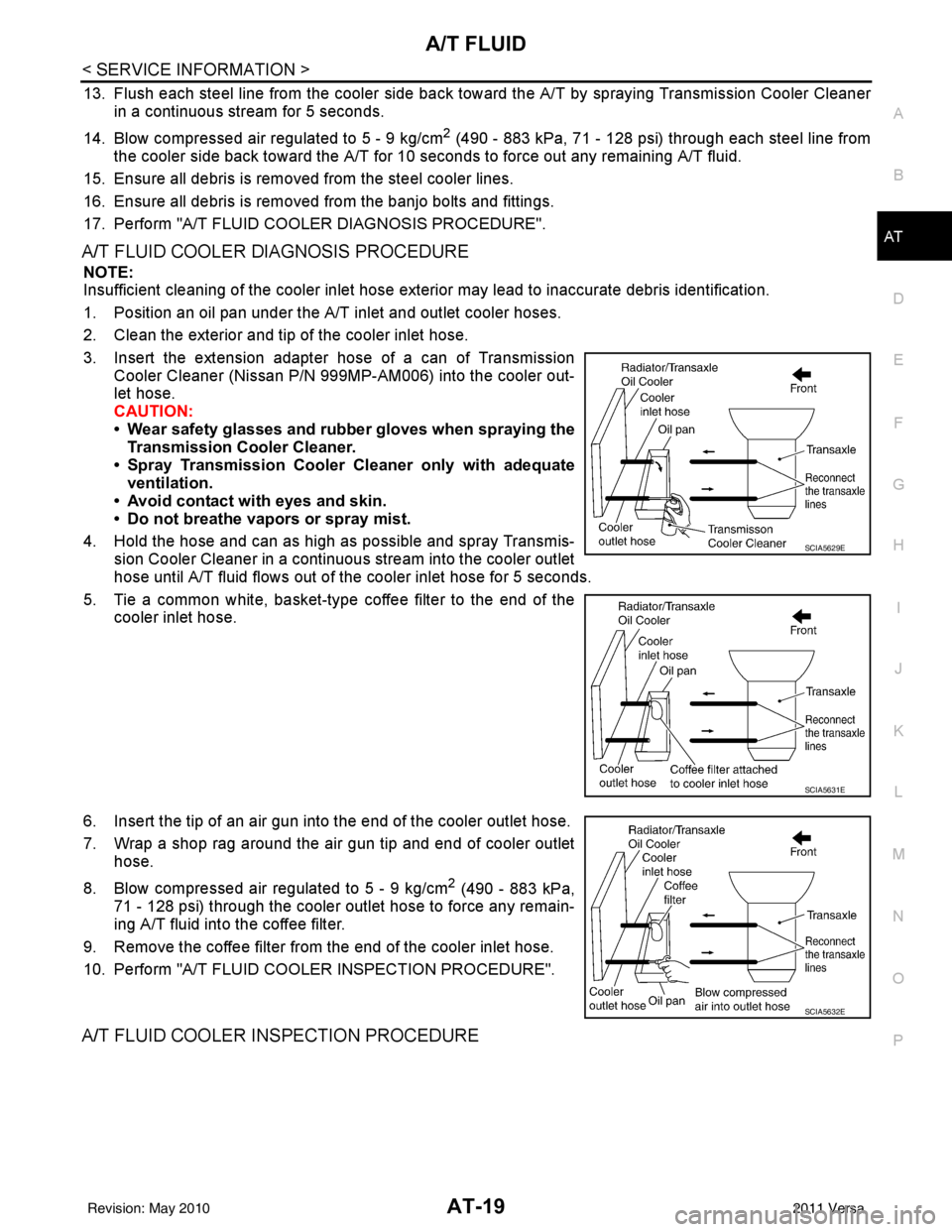
4. Hold the hose and can as high as possible and spray Transmis- sion Cooler Cleaner in a continuous stream into the cooler outlet
hose until A/T fluid flows out of t he cooler inlet hose for 5 seconds.
5. Tie a common white, basket-type coffee filter to the end of the cooler inlet hose.
6. Insert the tip of an air gun into the end of the cooler outlet hose.
7. Wrap a shop rag around the air gun tip and end of cooler outlet hose.
8. Blow compressed air regulated to 5 - 9 kg/cm
2 (490 - 883 kPa,
71 - 128 psi) through the cooler outlet hose to force any remain-
ing A/T fluid into the coffee filter.
9. Remove the coffee filter from the end of the cooler inlet hose.
10. Perform "A/T FLUID COOL ER INSPECTION PROCEDURE".
A/T FLUID COOLER INSPECTION PROCEDURE
SCIA5629E
SCIA5631E
SCIA5632E
Revision: May 2010 2011 Versa
Page 38 of 3787
A/T CONTROL SYSTEMAT-21
< SERVICE INFORMATION >
DE
F
G H
I
J
K L
M A
B
AT
N
O P
A/T CONTROL SYSTEM
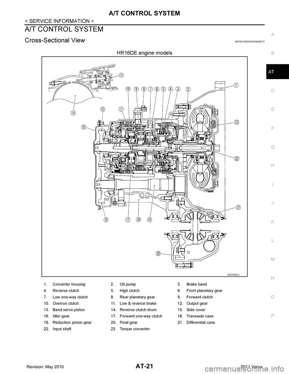
Cross-Sectional ViewINFOID:0000000005928073
HR16DE engine models
SCIA7651J
1. Converter housing 2. Oil pump3. Brake band
4. Reverse clutch 5. High clutch6. Front planetary gear
7. Low one-way clutch 8. Rear planetary gear9. Forward clutch
10. Overrun clutch 11. Low & reverse brake12. Output gear
13. Band servo piston 14. Reverse clutch drum15. Side cover
16. Idler gear 17. Forward one-way clutch 18. Transaxle case
19. Reduction pinion gear 20. Final gear 21. Differential case
22. Input shaft 23. Torque converter
Revision: May 2010 2011 Versa
Page 39 of 3787
AT-22
< SERVICE INFORMATION >
A/T CONTROL SYSTEM
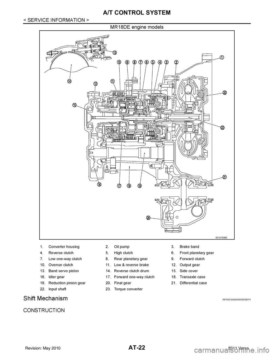
MR18DE engine models
Shift MechanismINFOID:0000000005928074
CONSTRUCTION
SCIA7938E
1. Converter housing2. Oil pump3. Brake band
4. Reverse clutch 5. High clutch6. Front planetary gear
7. Low one-way clutch 8. Rear planetary gear9. Forward clutch
10. Overrun clutch 11. Low & reverse brake12. Output gear
13. Band servo piston 14. Reverse clutch drum15. Side cover
16. Idler gear 17. Forward one-way clutch 18. Transaxle case
19. Reduction pinion gear 20. Final gear21. Differential case
22. Input shaft 23. Torque converter
Revision: May 2010 2011 Versa
Page 40 of 3787
A/T CONTROL SYSTEMAT-23
< SERVICE INFORMATION >
DE
F
G H
I
J
K L
M A
B
AT
N
O P
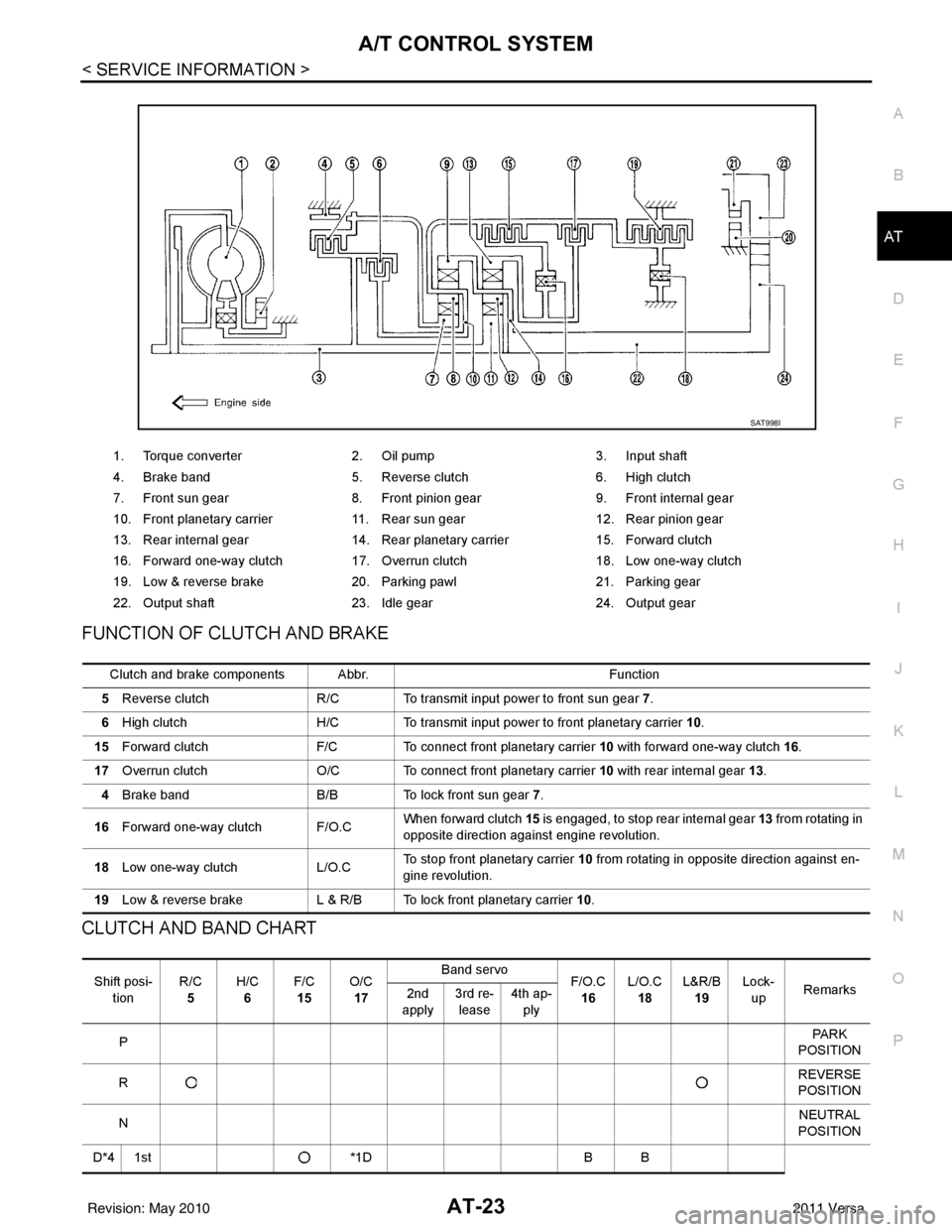
FUNCTION OF CLUTCH AND BRAKE
CLUTCH AND BAND CHART
1. Torque converter 2. Oil pump 3. Input shaft
4. Brake band 5. Reverse clutch 6. High clutch
7. Front sun gear 8. Front pinion gear 9. Front internal gear
10. Front planetary carrier 11. Rear sun gear 12. Rear pinion gear
13. Rear internal gear 14. Rear planetary carrier 15. Forward clutch
16. Forward one-way clutch 17. Overrun clutch 18. Low one-way clutch
19. Low & reverse brake 20. Parking pawl 21. Parking gear
22. Output shaft 23. Idle gear 24. Output gear
SAT998I
Clutch and brake components Abbr. Function
5 Reverse clutch R/C To transmit input power to front sun gear 7 .
6 High clutch H/C To transmit input power to front planetary carrier 10.
15 Forward clutch F/C To connect front planetary carrier 10 with forward one-way clutch 16.
17 Overrun clutch O/C To connect front planetary carrier 10 with rear internal gear 13 .
4 Brake band B/B To lock front sun gear 7.
16 Forward one-way clutch F/O.C When forward clutch 15
is engaged, to stop rear internal gear 13 from rotating in
opposite direction against engine revolution.
18 Low one-way clutch L/O.CTo stop front planetary carrier
10 from rotating in opposite direction against en-
gine revolution.
19 Low & reverse brake L & R/B To lock front planetary carrier 10.
Shift posi-
tion R/C
5 H/C
6 F/C
15 O/C
17 Band servo
F/O.C
16 L/O.C
18 L&R/B
19 Lock-
up Remarks
2nd
apply 3rd re-
lease 4th ap-
ply
P PA R K
POSITION
R REVERSE
POSITION
N NEUTRAL
POSITION
D*4 1st *1DB B
Revision: May 2010 2011 Versa
Page 44 of 3787
A/T CONTROL SYSTEMAT-27
< SERVICE INFORMATION >
DE
F
G H
I
J
K L
M A
B
AT
N
O P
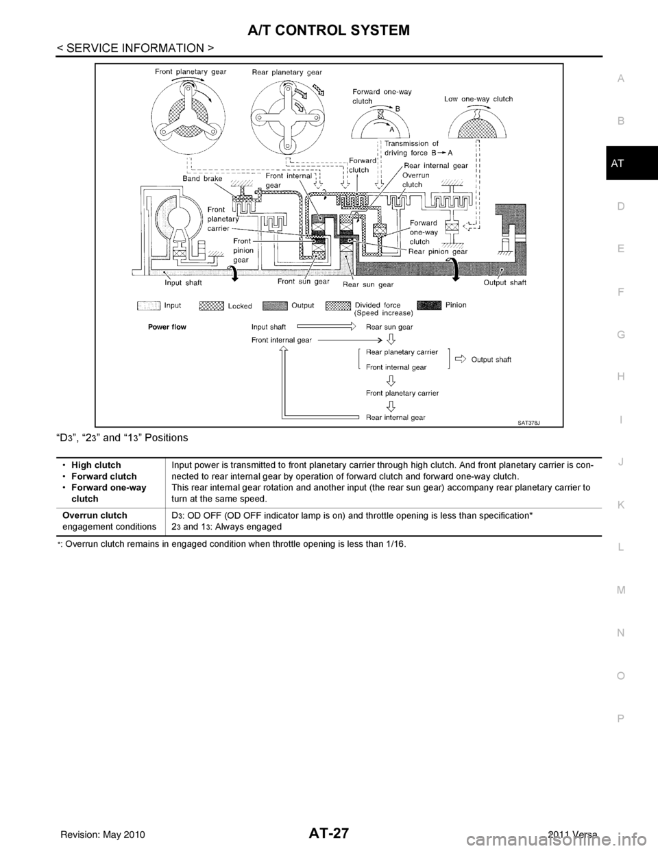
“D
3”, “23” and “13” Positions
*: Overrun clutch remains in engaged condition when throttle opening is less than 1/16.
SAT378J
•
High clutch
• Forward clutch
• Forward one-way
clutch Input power is transmitted to front planetary carrier through high clutch. And front planetary carrier is con-
nected to rear internal gear by operation of forward clutch and forward one-way clutch.
This rear internal gear rotation and another input (the rear sun gear) accompany rear planetary carrier to
turn at the same speed.
Overrun clutch
engagement conditions D
3: OD OFF (OD OFF indicator lamp is on) and throttle opening is less than specification*
2
3 and 13: Always engaged
Revision: May 2010 2011 Versa