2011 NISSAN TIIDA AT-217
[x] Cancel search: AT-217Page 110 of 3787
P0705 TRANSMISSION RANGE SWITCH A
AT-93
< SERVICE INFORMATION >
D E
F
G H
I
J
K L
M A
B
AT
N
O P
NG >> GO TO 3.
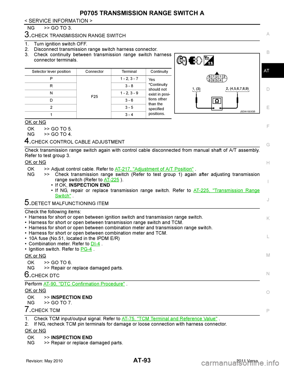
3.CHECK TRANSMISSION RANGE SWITCH
1. Turn ignition switch OFF.
2. Disconnect transmission range switch harness connector.
3. Check continuity between transmission range switch harness connector terminals.
OK or NG
OK >> GO TO 5.
NG >> GO TO 4.
4.CHECK CONTROL CABLE ADJUSTMENT
Check transmission range switch again with control cabl e disconnected from manual shaft of A/T assembly.
Refer to test group 3.
OK or NG
OK >> Adjust control cable. Refer to AT-217, "Adjustment of A/T Position" .
NG >> Check transmission range switch (Refer to test group 1) again after adjusting transmission range switch (Refer to AT-225
).
• If OK, INSPECTION END
• If NG, repair or replace transmission range switch. Refer to AT-225, "
Transmission Range
Switch" .
5.DETECT MALFUNCTIONING ITEM
Check the following items:
• Harness for short or open between ignition switch and transmission range switch.
• Harness for short or open between transmission range switch and TCM.
• Harness for short or open between combination meter and transmission range switch.
• Harness for short or open between combination meter and TCM.
• 10A fuse (No.51, located in the IPDM E/R)
• Combination meter. Refer to DI-4
.
• Ignition switch. Refer to PG-4
.
OK or NG
OK >> GO TO 6.
NG >> Repair or replace damaged parts.
6.CHECK DTC
Perform AT-90, "
DTC Confirmation Procedure" .
OK or NG
OK >> INSPECTION END
NG >> GO TO 7.
7.CHECK TCM
1. Check TCM input/output signal. Refer to AT-75, "
TCM Terminal and Reference Value" .
2. If NG, recheck TCM pin terminals for dam age or loose connection with harness connector.
OK or NG
OK >> INSPECTION END
NG >> Repair or replace damaged parts.
Selector lever position Connector Terminal Continuity
P
F251 - 2, 3 - 7
Ye s
*Continuity
should not
exist in posi-
tions other
than the
specified
positions.
R3
- 8
N 1 - 2, 3 - 9
D3 - 6
23 - 5
13 - 4
JSDIA1503GB
Revision: May 2010 2011 Versa
Page 111 of 3787
AT-94
< SERVICE INFORMATION >
P0705 TRANSMISSION RANGE SWITCH A
Component Inspection
INFOID:0000000005928120
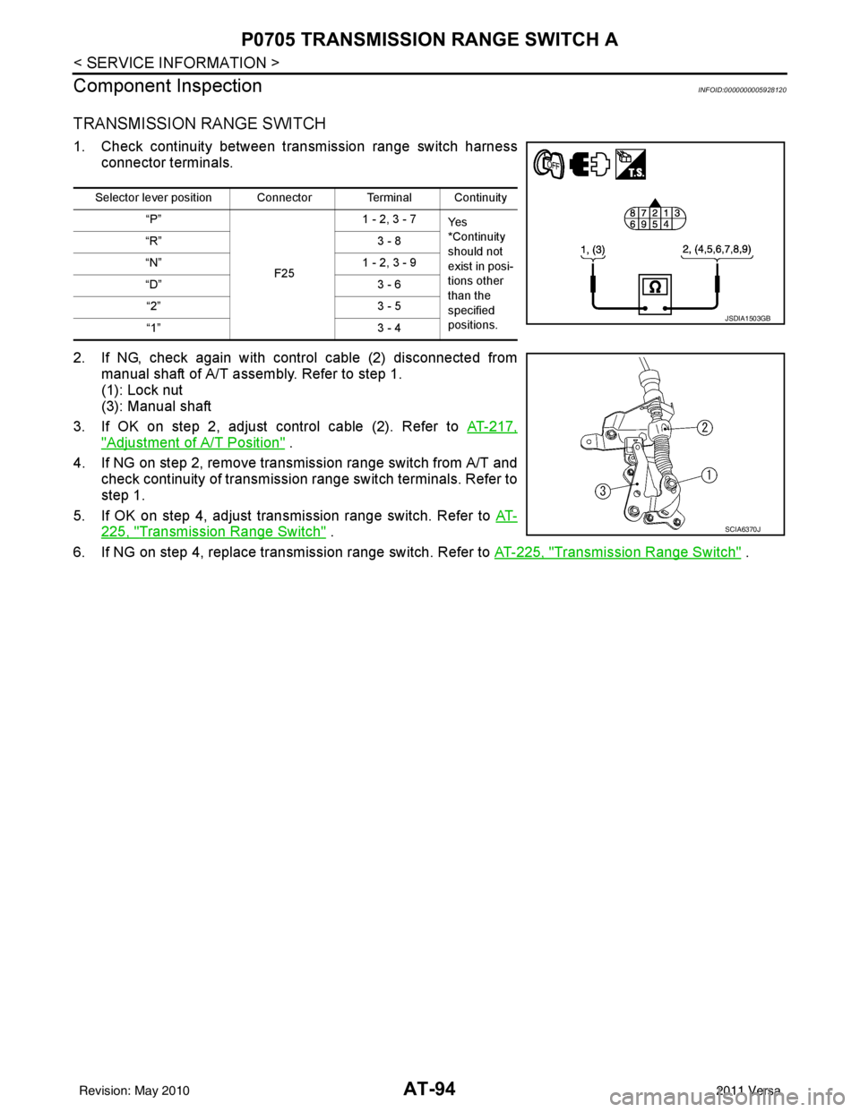
TRANSMISSION RANGE SWITCH
1. Check continuity between transmission range switch harness connector terminals.
2. If NG, check again with control cable (2) disconnected from manual shaft of A/T assembly. Refer to step 1.
(1): Lock nut
(3): Manual shaft
3. If OK on step 2, adjust control cable (2). Refer to AT-217,
"Adjustment of A/T Position" .
4. If NG on step 2, remove transmission range switch from A/T and check continuity of transmission range switch terminals. Refer to
step 1.
5. If OK on step 4, adjust trans mission range switch. Refer to AT-
225, "Transmission Range Switch" .
6. If NG on step 4, replace transmission range switch. Refer to AT-225, "
Transmission Range Switch" .
Selector lever position Connector Terminal Continuity
“P”
F251 - 2, 3 - 7
Ye s
*Continuity
should not
exist in posi-
tions other
than the
specified
positions.
“R”
3 - 8
“N” 1 - 2, 3 - 9
“D” 3 - 6
“2” 3 - 5
“1” 3 - 4
JSDIA1503GB
SCIA6370J
Revision: May 2010 2011 Versa
Page 190 of 3787
TR SW, OD SW AND CLOSED THROTTLE, WIDE OPEN THROTTLE POSITION
SIGNAL CIRCUIT
AT-173
< SERVICE INFORMATION >
DE
F
G H
I
J
K L
M A
B
AT
N
O P
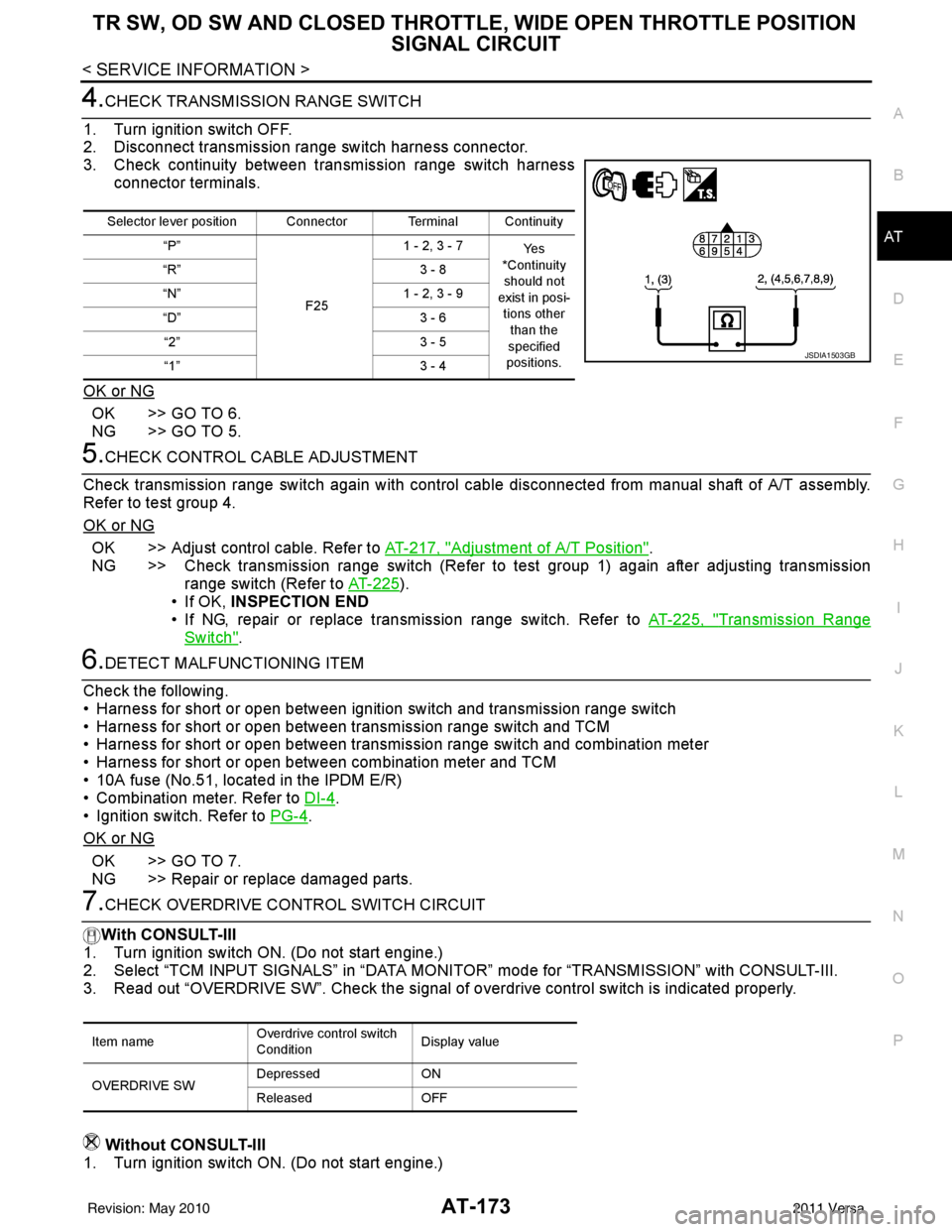
4.CHECK TRANSMISSION RANGE SWITCH
1. Turn ignition switch OFF.
2. Disconnect transmission range switch harness connector.
3. Check continuity between transmission range switch harness connector terminals.
OK or NG
OK >> GO TO 6.
NG >> GO TO 5.
5.CHECK CONTROL CABLE ADJUSTMENT
Check transmission range switch again with control cabl e disconnected from manual shaft of A/T assembly.
Refer to test group 4.
OK or NG
OK >> Adjust control cable. Refer to AT-217, "Adjustment of A/T Position".
NG >> Check transmission range switch (Refer to test group 1) again after adjusting transmission range switch (Refer to AT-225
).
• If OK, INSPECTION END
• If NG, repair or replace transmission range switch. Refer to AT-225, "
Transmission Range
Switch".
6.DETECT MALFUNCTIONING ITEM
Check the following.
• Harness for short or open between ignition switch and transmission range switch
• Harness for short or open between transmission range switch and TCM
• Harness for short or open between transmission range switch and combination meter
• Harness for short or open between combination meter and TCM
• 10A fuse (No.51, located in the IPDM E/R)
• Combination meter. Refer to DI-4
.
• Ignition switch. Refer to PG-4
.
OK or NG
OK >> GO TO 7.
NG >> Repair or replace damaged parts.
7.CHECK OVERDRIVE CO NTROL SWITCH CIRCUIT
With CONSULT-III
1. Turn ignition switch ON. (Do not start engine.)
2. Select “TCM INPUT SIGNALS” in “DATA MONI TOR” mode for “TRANSMISSION” with CONSULT-III.
3. Read out “OVERDRIVE SW”. Check the signal of ov erdrive control switch is indicated properly.
Without CONSULT-III
1. Turn ignition switch ON. (Do not start engine.)
Selector lever position Connector Terminal Continuity
“P”
F251 - 2, 3 - 7
Ye s
*Continuity should not
exist in posi-
tions other than the
specified
positions.
“R”
3 - 8
“N” 1 - 2, 3 - 9
“D” 3 - 6
“2” 3 - 5
“1” 3 - 4
JSDIA1503GB
Item nameOverdrive control switch
ConditionDisplay value
OVERDRIVE SW Depressed
ON
Released OFF
Revision: May 2010 2011 Versa
Page 192 of 3787
TR SW, OD SW AND CLOSED THROTTLE, WIDE OPEN THROTTLE POSITION
SIGNAL CIRCUIT
AT-175
< SERVICE INFORMATION >
DE
F
G H
I
J
K L
M A
B
AT
N
O P
11 .PERFORM SELF-DIAGNOSIS
Without CONSULT-III
Perform self-diagnosis. Refer to AT-82, "
Diagnosis Procedure without CONSULT-III".
OK or NG
OK >> INSPECTION END
NG − 1 >> Self-diagnosis does not activate: GO TO 12.
NG − 2 >> DTC is displayed: Check the malfunctioning system. Refer to AT-82, "
Diagnosis Procedure with-
out CONSULT-III".
12.CHECK TCM
1. Check TCM input/output signal. Refer to AT-75, "
TCM Terminal and Reference Value".
2. If NG, recheck TCM pin terminals for dam age or loose connection with harness connector.
OK or NG
OK >> INSPECTION END
NG >> Repair or replace damaged parts.
Component InspectionINFOID:0000000005928242
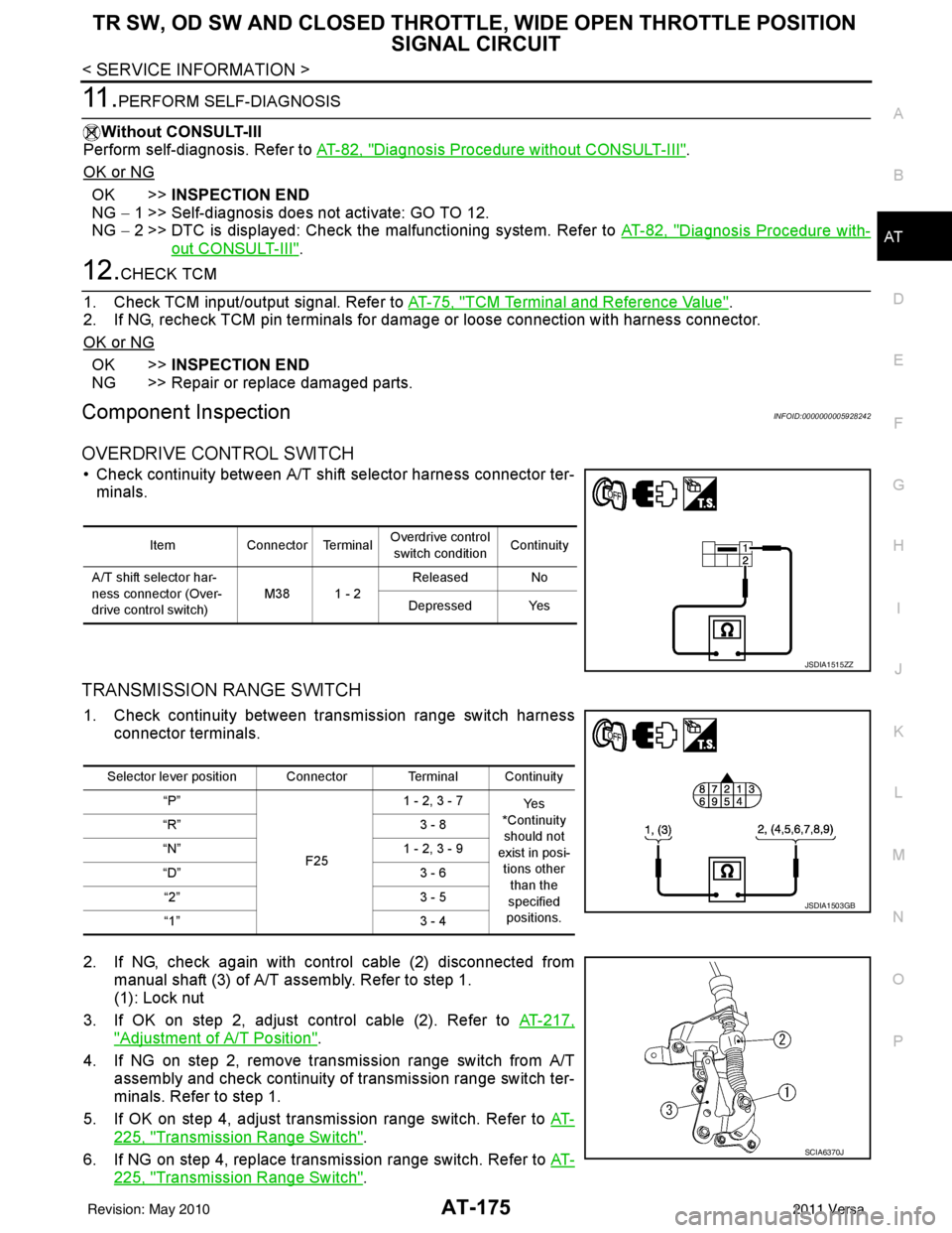
OVERDRIVE CONTROL SWITCH
• Check continuity between A/T shift selector harness connector ter- minals.
TRANSMISSION RANGE SWITCH
1. Check continuity between transmission range switch harness connector terminals.
2. If NG, check again with control cable (2) disconnected from manual shaft (3) of A/T assembly. Refer to step 1.
(1): Lock nut
3. If OK on step 2, adjust control cable (2). Refer to AT-217,
"Adjustment of A/T Position".
4. If NG on step 2, remove transmission range switch from A/T assembly and check continuity of transmission range switch ter-
minals. Refer to step 1.
5. If OK on step 4, adjust transmission range switch. Refer to AT-
225, "Transmission Range Switch".
6. If NG on step 4, replace transmission range switch. Refer to AT-
225, "Transmission Range Switch".
ItemConnector Terminal Overdrive control
switch condition Continuity
A/T shift selector har-
ness connector (Over-
drive control switch) M38 1 - 2Released No
Depressed Yes
JSDIA1515ZZ
Selector lever position Connector Terminal Continuity “P”
F251 - 2, 3 - 7
Ye s
*Continuity
should not
exist in posi- tions other
than the
specified
positions.
“R”
3 - 8
“N” 1 - 2, 3 - 9
“D” 3 - 6
“2” 3 - 5
“1” 3 - 4
JSDIA1503GB
SCIA6370J
Revision: May 2010 2011 Versa
Page 199 of 3787

AT-182
< SERVICE INFORMATION >
TROUBLE DIAGNOSIS FOR SYMPTOMS
3. Check continuity between TCM connector terminals and ground.Refer to AT-168, "
Wiring Diagram - AT - MAIN" .
OK or NG
OK >> GO TO 5.
NG >> Repair open circuit or short to ground or short to power in harness or connectors.
5.DETECT MALFUNCTIONING ITEM
Check the following.
• Harness for short or open between ignition switch and combination meter
• Combination meter. Refer to DI-4
.
OK or NG
OK >> GO TO 6.
NG >> Repair or replace damaged parts.
6.CHECK SYMPTOM
Check again. Refer to AT-56, "
Check Before Engine Is Started" .
OK or NG
OK >> INSPECTION END
NG >> GO TO 7.
7.CHECK TCM
1. Check TCM input/output. Refer to AT-75, "
TCM Terminal and Reference Value" .
2. If NG, recheck TCM pin terminals for damage or loose connection with harness connector.
OK or NG
OK >> INSPECTION END
NG >> Repair or replace damaged parts.
Engine Cannot Be Started in "P" and "N" PositionINFOID:0000000005928248
SYMPTOM:
•Engine cannot be started with select or lever in “P” or “N” position.
• Engine can be started with selector lever in “D”, “2”, “1” or “R” position.
DIAGNOSTIC PROCEDURE
1.CHECK TRANSMISSION RANGE SWITCH
Check continuity between transmission range switch harness con-
nector terminals. Refer to AT-91, "
Wiring Diagram - AT - TR/SW" .
OK or NG
OK >> GO TO 3.
NG >> GO TO 2.
2.CHECK TRANSMISSION RANGE SWITCH
Check transmission range switch again with control cabl e disconnected from manual shaft of A/T assembly.
Refer to test group 1.
OK or NG
OK >> Adjust A/T position. Refer to AT-217, "Adjustment of A/T Position" .
Item ConnectorTerminalContinuity
TCM connector E32 25, 48 - GroundYes
SCIA2671E
Selector lever position Connector terminal Continuity
“P”, “N” F251 - 2 Ye s
Other positions No
JSDIA1516ZZ
Revision: May 2010 2011 Versa
Page 200 of 3787
TROUBLE DIAGNOSIS FOR SYMPTOMSAT-183
< SERVICE INFORMATION >
DE
F
G H
I
J
K L
M A
B
AT
N
O P
NG >> 1. Check transmission range switch (Refer to test group 1.) again after adjusting transmission
range switch (Refer to AT-225
).
- If OK, INSPECTION END
- If NG, repair or replace transmission range switch. Refer to AT-225, "
Transmission Range
Switch" .
3.CHECK STARTING SYSTEM
Check starting system. Refer to SC-9
.
OK or NG
OK >> INSPECTION END
NG >> Repair or replace damaged parts.
In "P" Position, Vehicle Moves Forward or Backward When PushedINFOID:0000000005928249
SYMPTOM:
Vehicle moves when it is pushed forward or backward with selector lever in “P” position.
DIAGNOSTIC PROCEDURE
1.CHECK A/T POSITION
Check A/T position. Refer to AT-217, "
Checking of A/T Position" .
OK or NG
OK >> GO TO 2.
NG >> Adjust A/T position. Refer to AT-217, "
Adjustment of A/T Position" .
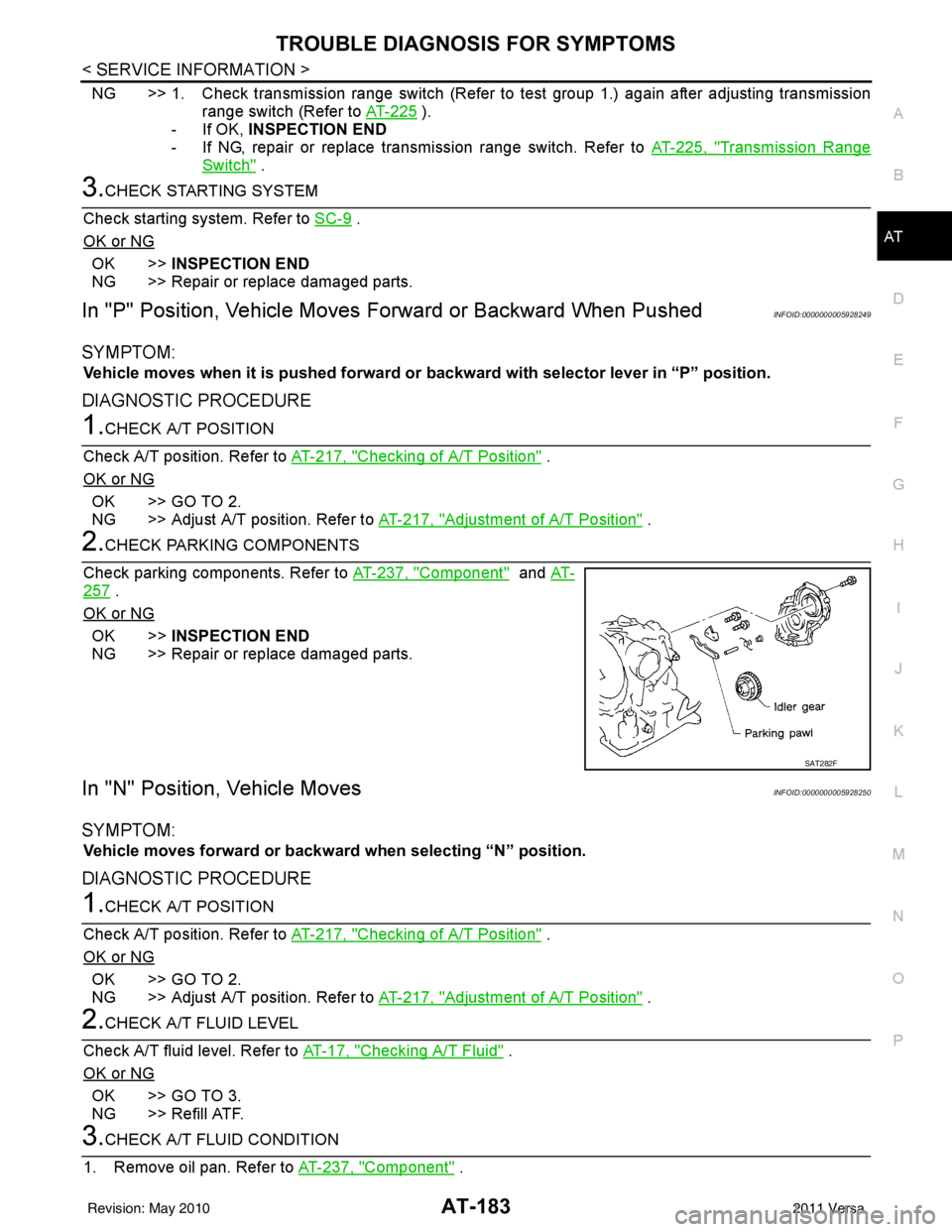
2.CHECK PARKING COMPONENTS
Check parking components. Refer to AT-237, "
Component" and AT-
257 .
OK or NG
OK >> INSPECTION END
NG >> Repair or replace damaged parts.
In "N" Position, Vehicle MovesINFOID:0000000005928250
SYMPTOM:
Vehicle moves forward or backwar d when selecting “N” position.
DIAGNOSTIC PROCEDURE
1.CHECK A/T POSITION
Check A/T position. Refer to AT-217, "
Checking of A/T Position" .
OK or NG
OK >> GO TO 2.
NG >> Adjust A/T position. Refer to AT-217, "
Adjustment of A/T Position" .
2.CHECK A/T FLUID LEVEL
Check A/T fluid level. Refer to AT-17, "
Checking A/T Fluid" .
OK or NG
OK >> GO TO 3.
NG >> Refill ATF.
3.CHECK A/T FLUID CONDITION
1. Remove oil pan. Refer to AT-237, "
Component" .
SAT282F
Revision: May 2010 2011 Versa
Page 206 of 3787
TROUBLE DIAGNOSIS FOR SYMPTOMSAT-189
< SERVICE INFORMATION >
DE
F
G H
I
J
K L
M A
B
AT
N
O P
7.DETECT MALFUNCTIONING ITEM
1. Remove control valve assembly. Refer to AT-222, "
Control Valve Assembly and Accumulators" .
2. Check the following items:
- Shift valve A
- Shift valve B
- Shift solenoid valve A
- Shift solenoid valve B
- Pilot valve
- Pilot filter
OK or NG
OK >> GO TO 8.
NG >> Repair or replace damage parts.
8.CHECK SYMPTOM
Check again. Refer to AT-58, "
Cruise Test - Part 1" .
OK or NG
OK >> INSPECTION END
NG >> GO TO 9.
9.CHECK TCM
1. Check TCM input/output signals. Refer to AT-75, "
TCM Terminal and Reference Value" .
2. If NG, recheck TCM pin terminals for dam age or loose connection with harness connector.
OK or NG
OK >> INSPECTION END
NG >> Repair or replace damaged parts.
A/T Does Not Shift: D1→ D2or Does Not Kickdown: D4→ D2INFOID:0000000005928255
SYMPTOM:
•A/T does not shift from D1 to D2 at the specified speed on “Cruise Test — Part 1”.
• A/T does not shift from D
4 to D2 when depressing accelerator pedal fully at the specified speed on
“Cruise Test — Part 2”.
DIAGNOSTIC PROCEDURE
1.CHECK SYMPTOM
Check symptom . Refer to AT-56, "
Check at Idle" and AT-58, "Cruise Test - Part 1" .
Are
“Vehicle Dose Not Creep Forward in “D”, “2” or “1” Position” and “Vehicle Cannot Be Started from D1” OK?
YES >> GO TO 2.
NO >> Go to AT-186, "
Vehicle Does Not Creep Forward in "D", "2" or "1" Position" and AT-187, "Vehicle
Cannot Be Started from D1" .
2.CHECK A/T POSITION
Check A/T position. Refer to AT-217, "
Checking of A/T Position" .
OK or NG
OK >> GO TO 3.
NG >> Adjust A/T position. Refer to AT-217, "
Adjustment of A/T Position" .
3.CHECK OUTPUT SPEED SENSOR AND VEHICLE SPEED SIGNAL CIRCUIT
Check output speed sensor and vehicle speed signal circuit. Refer to AT-100
and AT-153 .
OK or NG
OK >> GO TO 4.
NG >> Repair or replace output speed sensor and vehicle speed signal circuits.
4.CHECK ACCELERATOR PEDAL POSITION SENSOR
Check accelerator pedal position sensor. Refer to EC-415, "
Description" (HR16DE), EC-982, "Component
Description" (MR18DE).
Revision: May 2010 2011 Versa
Page 208 of 3787
TROUBLE DIAGNOSIS FOR SYMPTOMSAT-191
< SERVICE INFORMATION >
DE
F
G H
I
J
K L
M A
B
AT
N
O P
A/T does not shift from D2 to D3 at the specified speed on “Cruise Test — Part 1” and “Cruise Test —
Part 2”.
DIAGNOSTIC PROCEDURE
1.CHECK SYMPTOM
Check symptom. Refer to AT-56, "
Check at Idle" and AT-58, "Cruise Test - Part 1" .
Are
“Vehicle Does Not Creep Forward in “D”, “2” or “1” Position” and “Vehicle Cannot Be Started from D1” OK?
YES >> GO TO 2.
NO >> Go to AT-186, "
Vehicle Does Not Creep Forward in "D", "2" or "1" Position" and AT-187, "Vehicle
Cannot Be Started from D1" .
2.CHECK A/T POSITION
Check A/T position. Refer to AT-217, "
Checking of A/T Position" .
OK or NG
OK >> GO TO 3.
NG >> Adjust A/T position. Refer to AT-217, "
Adjustment of A/T Position" .
3.CHECK OUTPUT SPEED SENSOR AND VEHICLE SPEED SIGNAL CIRCUIT
Check output speed sensor and vehicle speed signal circuit. Refer to AT-100
and AT-153 .
OK or NG
OK >> GO TO 4.
NG >> Repair or replace output speed sensor and vehicle speed signal circuits.
4.CHECK ACCELERATOR PEDAL POSITION SENSOR
Check accelerator pedal position sensor. Refer to EC-415, "
Description" (HR16DE), EC-982, "Component
Description" (MR18DE).
OK or NG
OK >> GO TO 5.
NG >> Repair or replace accelerator pedal position sensor.
5.CHECK A/T FLUID CONDITION
1. Remove oil pan. Refer to AT-237, "
Component" .
2. Check A/T fluid condition. Refer to AT-51, "
Inspections Before Trouble Diagnosis" .
OK or NG
OK >> GO TO 7.
NG >> GO TO 6.
6.DETECT MALFUNCTIONING ITEM
1. Remove control valve assembly. Refer to AT-222, "
Control Valve Assembly and Accumulators" .
2. Check the following items:
- Shift valve B
- Shift solenoid valve B
- Pilot valve
- Pilot filter
3. Disassemble A/T. Refer to AT-257, "
Disassembly" .
4. Check the following items:
- Servo piston assembly
- High clutch assembly. Refer to AT-302, "
High Clutch" .
- Oil pump assembly. Refer to AT-278, "
Oil Pump" .
OK or NG
OK >> GO TO 8.
NG >> Repair or replace damaged parts.
7.DETECT MALFUNCTIONING ITEM
1. Remove control valve assembly. Refer to AT-222, "
Control Valve Assembly and Accumulators" .
2. Check the following items:
- Shift valve B
Revision: May 2010 2011 Versa