Page 28 of 3787
PREPARATIONAT-11
< SERVICE INFORMATION >
DE
F
G H
I
J
K L
M A
B
AT
N
O P
PREPARATION
Special Service ToolINFOID:0000000005928068
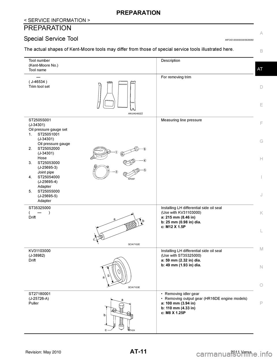
The actual shapes of Kent-Moore tools may differ from those of special service tools illustrated here.
Tool number
(Kent-Moore No.)
Tool name Description
—
( J-46534 )
Trim tool set For removing trim
ST2505S001
(J-34301)
Oil pressure gauge set
1. ST25051001 (J-34301)
Oil pressure gauge
2. ST25052000 (J-34301)
Hose
3. ST25053000 (J-25695-3)
Joint pipe
4. ST25054000 (J-25695-4)
Adapter
5. ST25055000 (J-25695-5)
Adapter Measuring line pressure
ST35325000
( — )
Drift Installing LH differential side oil seal
(Use with KV31103000)
a: 215 mm (8.46 in)
b: 25 mm (0.98 in) dia.
c: M12 X 1.5P
KV31103000
(J-38982)
Drift Installing LH differential side oil seal
(Use with ST35325000)
a: 59 mm (2.32 in) dia.
b: 49 mm (1.93 in) dia.
ST27180001
(J-25726-A)
Puller • Removing idler gear
• Removing output gear (HR16DE engine models)
a: 100 mm (3.94 in)
b: 110 mm (4.33 in)
c: M8 X 1.25P
AWJIA0483ZZ
NT097
SCIA7102E
SCIA7103E
NT424
Revision: May 2010
2011 Versa
Page 30 of 3787
PREPARATIONAT-13
< SERVICE INFORMATION >
DE
F
G H
I
J
K L
M A
B
AT
N
O P
ST35272000
(J-26092)
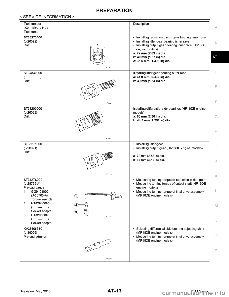
Drift • Installing reduction pinion gear bearing inner race
• Installing idler gear bearing inner race
• Installing output gear bearing inner race (HR16DE
engine models)
a: 72 mm (2.83 in) dia.
b: 40 mm (1.57 in) dia.
c: 35.5 mm (1.398 in) dia.
ST37830000
( — )
Drift Installing idler gear bearing outer race
a: 61.9 mm (2.437 in) dia.
b: 39 mm (1.54 in) dia.
ST33200000
(J-26082)
Drift Installing differential side bearings (HR16DE engine
models)
a: 60 mm (2.36 in) dia.
b: 44.5 mm (1.752 in) dia.
ST35271000
(J-26091)
Drift • Installing idler gear
• Installing output gear (HR16DE engine models)
a: 72 mm (2.83 in) dia.
b: 63 mm (2.48 in) dia.
ST3127S000
(J-25765-A)
Preload gauge
1. GG9103000 (J-25765-A)
Torque wrench
2. HT62940000 ( — )
Socket adapter
3. HT62900000 ( — )
Socket adapter • Measuring turning torque of reduction pinion gear
• Measuring turning torque of output shaft (HR16DE
engine models)
• Measuring turning torque of final drive assembly (MR18DE engine models)
KV38105710
(J-39026)
Preload adapter • Selecting differential side bearing adjusting shim
(MR18DE engine models)
• Measuring turning torque of final drive assembly
(MR18DE engine models)
Tool number
(Kent-Moore No.)
Tool name
Description
NT107
NT084
NT091
NT115
NT124
NT087
Revision: May 2010
2011 Versa
Page 31 of 3787
AT-14
< SERVICE INFORMATION >
PREPARATION
Commercial Service Tool
INFOID:0000000005928069
ST35321000
( — )
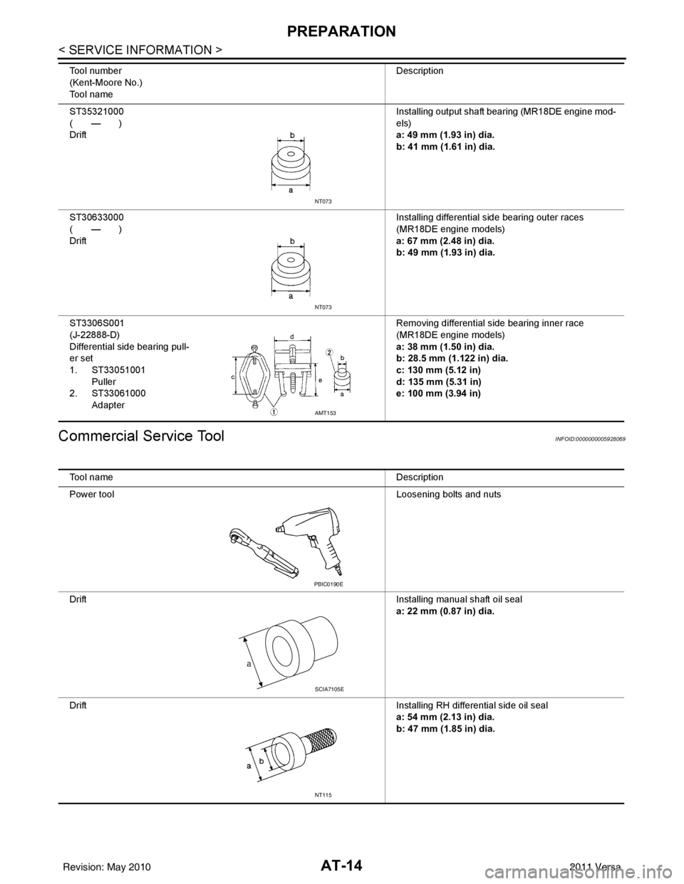
Drift Installing output shaft bearing (MR18DE engine mod-
els)
a: 49 mm (1.93 in) dia.
b: 41 mm (1.61 in) dia.
ST30633000
( — )
Drift Installing differential side bearing outer races
(MR18DE engine models)
a: 67 mm (2.48 in) dia.
b: 49 mm (1.93 in) dia.
ST3306S001
(J-22888-D)
Differential side bearing pull-
er set
1. ST33051001 Puller
2. ST33061000 Adapter Removing differential side bearing inner race
(MR18DE engine models)
a: 38 mm (1.50 in) dia.
b: 28.5 mm (1.122 in) dia.
c: 130 mm (5.12 in)
d: 135 mm (5.31 in)
e: 100 mm (3.94 in)
Tool number
(Kent-Moore No.)
Tool name
Description
NT073
NT073
AMT153
Tool name
Description
Power tool Loosening bolts and nuts
Drift Installing manual shaft oil seal
a: 22 mm (0.87 in) dia.
Drift Installing RH differential side oil seal
a: 54 mm (2.13 in) dia.
b: 47 mm (1.85 in) dia.
PBIC0190E
SCIA7105E
NT115
Revision: May 2010 2011 Versa
Page 247 of 3787
AT-230
< SERVICE INFORMATION >
ON-VEHICLE SERVICE
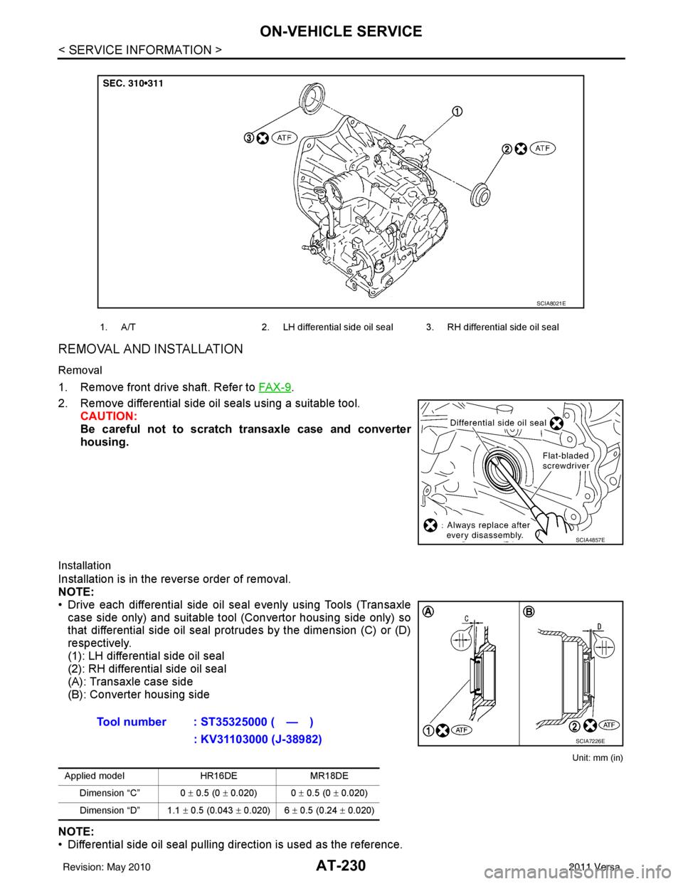
REMOVAL AND INSTALLATION
Removal
1. Remove front drive shaft. Refer to FA X - 9.
2. Remove differential side oil seals using a suitable tool. CAUTION:
Be careful not to scratch transaxle case and converter
housing.
Installation
Installation is in the reverse order of removal.
NOTE:
• Drive each differential side oil seal evenly using Tools (Transaxlecase side only) and suitable tool (Convertor housing side only) so
that differential side oil seal prot rudes by the dimension (C) or (D)
respectively.
(1): LH differential side oil seal
(2): RH differential side oil seal
(A): Transaxle case side
(B): Converter housing side
Unit: mm (in)
NOTE:
• Differential side oil seal pulling direction is used as the reference.
1. A/T 2. LH differential side oil seal 3. RH differential side oil seal
SCIA8021E
SCIA4857E
Tool number : ST35325000 ( — )
: KV31103000 (J-38982)
Applied model HR16DEMR18DE
Dimension “C” 0 ± 0.5 (0 ± 0.020) 0 ± 0.5 (0 ± 0.020)
Dimension “D” 1.1 ± 0.5 (0.043 ± 0.020) 6 ± 0.5 (0.24 ± 0.020)
SCIA7226E
Revision: May 2010 2011 Versa
Page 345 of 3787
AT-328
< SERVICE INFORMATION >
REPAIR FOR COMPONENT PARTS
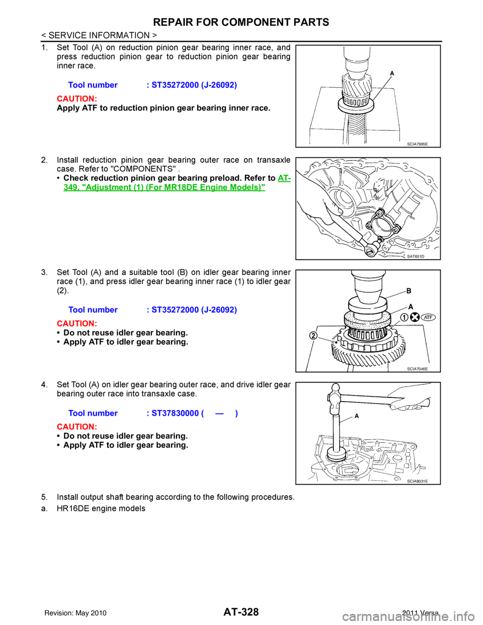
1. Set Tool (A) on reduction pinion gear bearing inner race, andpress reduction pinion gear to reduction pinion gear bearing
inner race.
CAUTION:
Apply ATF to reduction pini on gear bearing inner race.
2. Install reduction pinion gear bearing outer race on transaxle case. Refer to "COMPONENTS" .
•Check reduction pinion gear bearing preload. Refer to AT-
349, "Adjustment (1) (For MR18DE Engine Models)"
3. Set Tool (A) and a suitable tool (B) on idler gear bearing inner
race (1), and press idler gear bearing inner race (1) to idler gear
(2).
CAUTION:
• Do not reuse idler gear bearing.
• Apply ATF to idler gear bearing.
4. Set Tool (A) on idler gear bearing outer race, and drive idler gear bearing outer race into transaxle case.
CAUTION:
• Do not reuse idler gear bearing.
• Apply ATF to idler gear bearing.
5. Install output shaft bearing according to the following procedures.
a. HR16DE engine models Tool number : ST35272000 (J-26092)
SCIA7995E
SAT651D
Tool number : ST35272000 (J-26092)
SCIA7046E
Tool number : ST37830000 ( — )
SCIA8031E
Revision: May 2010
2011 Versa
Page 361 of 3787
AT-344
< SERVICE INFORMATION >
ASSEMBLY
ASSEMBLY
Assembly (1)INFOID:0000000005928303
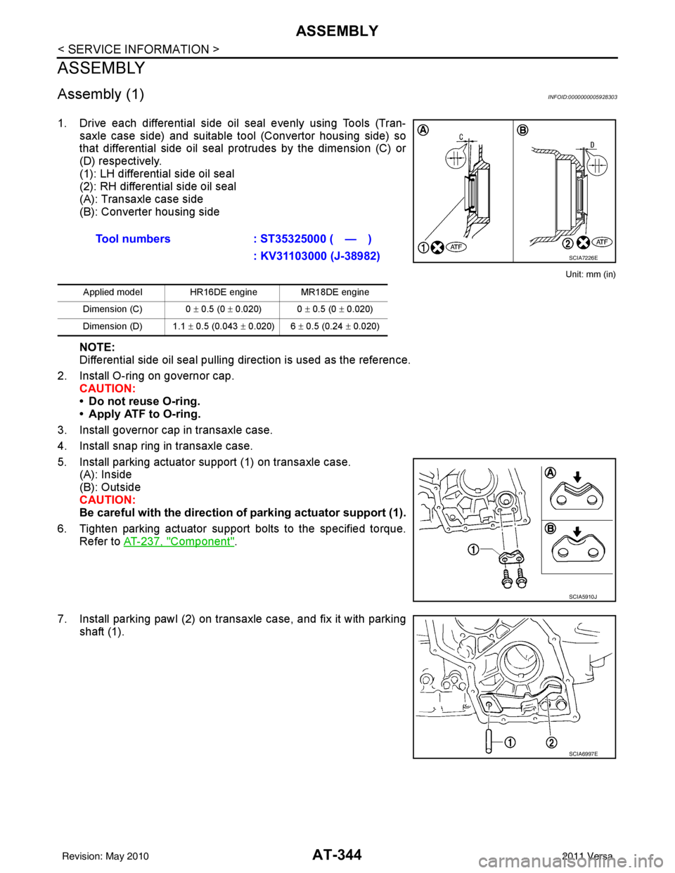
1. Drive each differential side oil seal evenly using Tools (Tran-saxle case side) and suitable tool (Convertor housing side) so
that differential side oil seal protrudes by the dimension (C) or
(D) respectively.
(1): LH differential side oil seal
(2): RH differential side oil seal
(A): Transaxle case side
(B): Converter housing side
Unit: mm (in)
NOTE:
Differential side oil seal pulling direction is used as the reference.
2. Install O-ring on governor cap. CAUTION:
• Do not reuse O-ring.
• Apply ATF to O-ring.
3. Install governor cap in transaxle case.
4. Install snap ring in transaxle case.
5. Install parking actuator support (1) on transaxle case. (A): Inside
(B): Outside
CAUTION:
Be careful with the direction of parking actuator support (1).
6. Tighten parking actuator support bolts to the specified torque. Refer to AT-237, "
Component".
7. Install parking pawl (2) on transaxle case, and fix it with parking shaft (1).Tool numbers
: ST35325000 ( — )
: KV31103000 (J-38982)
Applied model HR16DE engine MR18DE engine
Dimension (C) 0 ± 0.5 (0 ± 0.020) 0 ± 0.5 (0 ± 0.020)
Dimension (D) 1.1 ± 0.5 (0.043 ± 0.020) 6 ± 0.5 (0.24 ± 0.020)
SCIA7226E
SCIA5910J
SCIA6997E
Revision: May 2010 2011 Versa
Page 367 of 3787
AT-350
< SERVICE INFORMATION >
ASSEMBLY
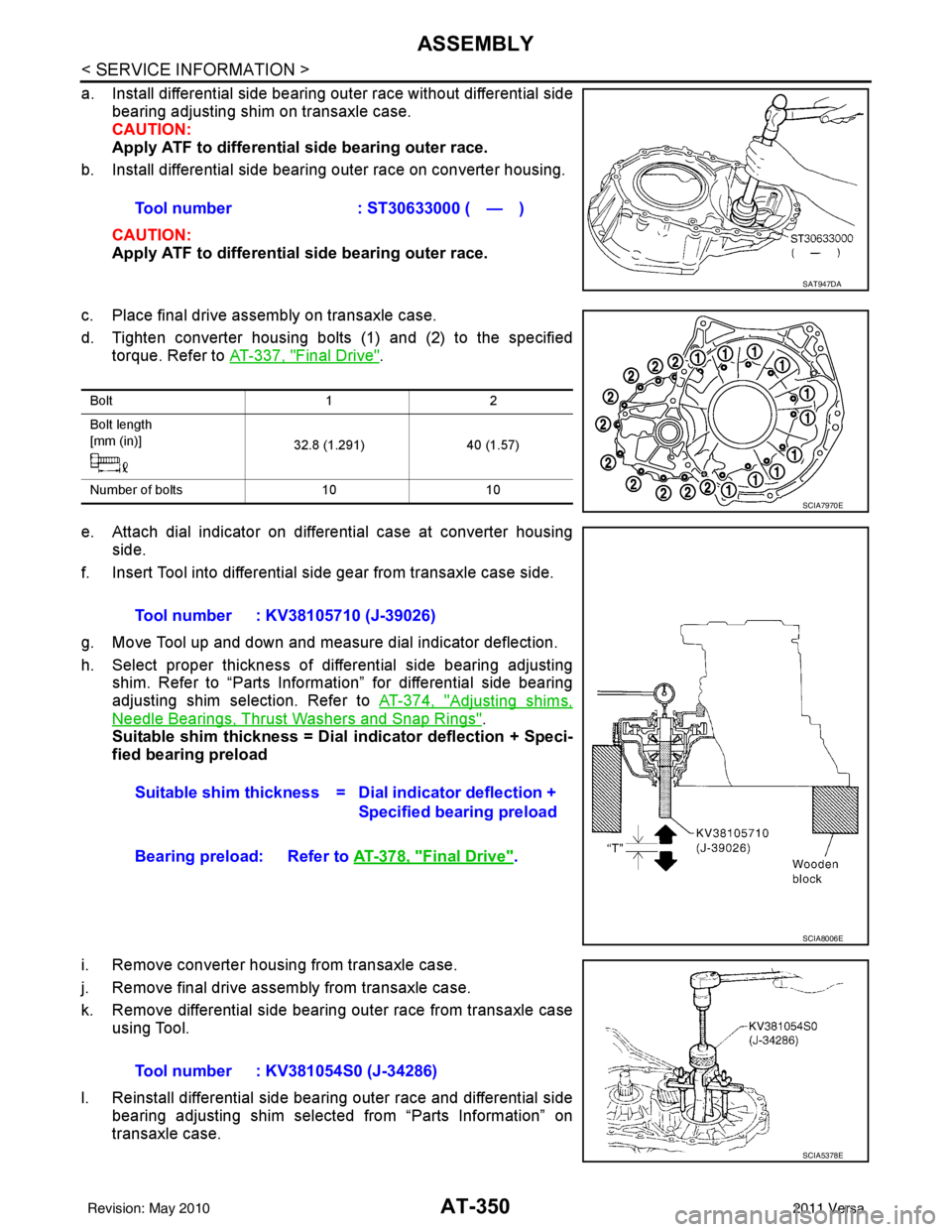
a. Install differential side bearing outer race without differential sidebearing adjusting shim on transaxle case.
CAUTION:
Apply ATF to differential side bearing outer race.
b. Install differential side bearing outer race on converter housing.
CAUTION:
Apply ATF to differential side bearing outer race.
c. Place final drive assembly on transaxle case.
d. Tighten converter housing bolts (1) and (2) to the specified torque. Refer to AT-337, "
Final Drive".
e. Attach dial indicator on differential case at converter housing side.
f. Insert Tool into differential side gear from transaxle case side.
g. Move Tool up and down and measure dial indicator deflection.
h. Select proper thickness of differential side bearing adjusting shim. Refer to “Parts Information” for differential side bearing
adjusting shim selection. Refer to AT-374, "
Adjusting shims,
Needle Bearings, Thrust Washers and Snap Rings".
Suitable shim thickness = Dial indicator deflection + Speci-
fied bearing preload
i. Remove converter housing from transaxle case.
j. Remove final drive assembly from transaxle case.
k. Remove differential side bearing outer race from transaxle case using Tool.
l. Reinstall differential side bearing outer race and differential side bearing adjusting shim selected from “Parts Information” on
transaxle case.Tool number : ST30633000 ( — )
SAT947DA
Bolt
12
Bolt length
[mm (in)] 32.8 (1.291)40 (1.57)
Number of bolts 1010
SCIA7970E
Tool number : KV38105710 (J-39026)
Suitable shim thickness = D ial indicator deflection +
Specified bearing preload
Bearing preload: Refer to AT-378, "
Final Drive".
SCIA8006E
Tool number : KV381054S0 (J-34286)
SCIA5378E
Revision: May 2010 2011 Versa
Page 1004 of 3787
![NISSAN TIIDA 2011 Service Repair Manual CO-4
< PRECAUTION >[HR16DE]
PRECAUTIONS
1. Remove old liquid gasket adhering to the liquid gasket applica-
tion surface and the mating surface, using scraper.
• Remove liquid gasket completely from](/manual-img/5/57396/w960_57396-1003.png "NISSAN TIIDA 2011 Service Repair Manual CO-4
< PRECAUTION >[HR16DE]
PRECAUTIONS
1. Remove old liquid gasket adhering to the liquid gasket applica-
tion surface and the mating surface, using scraper.
• Remove liquid gasket completely from")
CO-4
< PRECAUTION >[HR16DE]
PRECAUTIONS
1. Remove old liquid gasket adhering to the liquid gasket applica-
tion surface and the mating surface, using scraper.
• Remove liquid gasket completely from the groove of the liquidgasket application surface, bolts, and bolt holes.
2. Thoroughly clean the mating surfaces and remove adhering moisture, grease and foreign materials.
3. Attach liquid gasket tube to Tool.
Use Genuine RTV Silicone Seal ant or equivalent. Refer to GI-42, "
Recommended Chemical Prod-
uct and Sealant".
4. Apply liquid gasket without breaks to the specif ied location with the specified dimensions.
• If there is a groove for the liquid gasket application, apply liquid gasket to the groove.
• As for the bolt holes, normally apply liquid gasket inside the holes. Occasionally, it should be applied outside the holes.
Make sure to read the text of service manual.
• Within five minutes of liquid gasket application, install the mat- ing component.
• If liquid gasket protrudes, wipe it off immediately.
• Do not retighten nuts or bolts after the installation.
• After 30 minutes or more have passed from the installation, fill engine oil and engine coolant.
CAUTION:
If there are specific instructions in this manual, observe them.
Tool number : WS39930000 ( — )
PBIC0003E
WBIA0567E
SEM159F
Revision: May 2010
2011 Versa