2011 NISSAN TIIDA oil temperature
[x] Cancel search: oil temperaturePage 3180 of 3787
PERIODIC MAINTENANCEMA-9
< SERVICE INFORMATION >
C
DE
F
G H
I
J
K
M A
B
MA
N
O P
PERIODIC MAINTENANCE
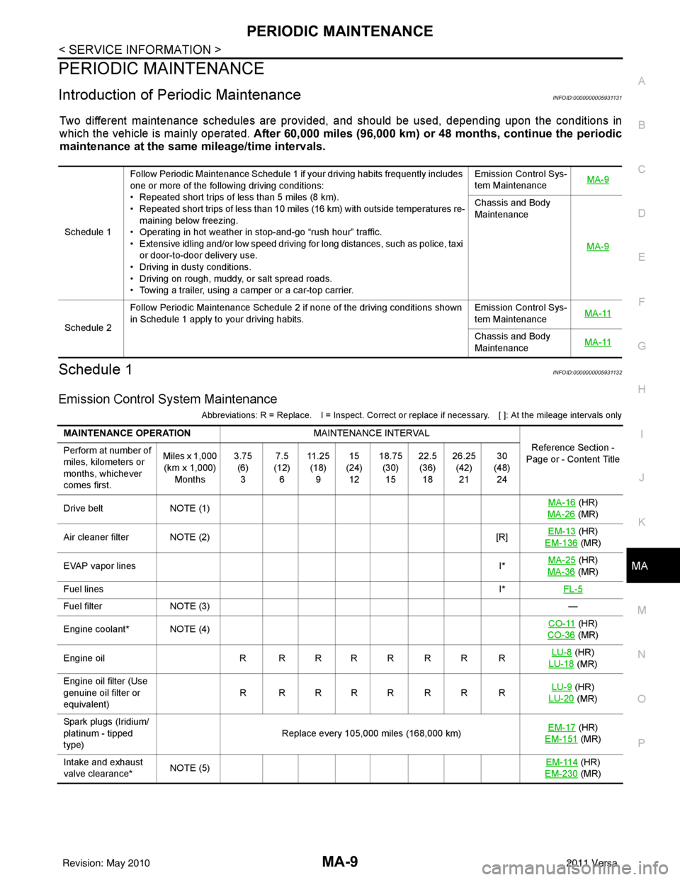
Introduction of Periodic MaintenanceINFOID:0000000005931131
Two different maintenance schedules are provi ded, and should be used, depending upon the conditions in
which the vehicle is mainly operated. After 60,000 miles (96,000 km) or 48 months, continue the periodic
maintenance at the same mileage/time intervals.
Schedule 1INFOID:0000000005931132
Emission Control System Maintenance
Abbreviations: R = Replace. I = Inspect. Correct or r eplace if necessary. [ ]: At the mileage intervals only
Schedule 1Follow Periodic Maintenance Schedule 1 if your driving habits frequently includes
one or more of the following driving conditions:
• Repeated short trips of less than 5 miles (8 km).
• Repeated short trips of less than 10 miles (16 km) with outside temperatures re-
maining below freezing.
• Operating in hot weather in stop-and-go “rush hour” traffic.
• Extensive idling and/or low speed driving for long distances, such as police, taxi
or door-to-door delivery use.
• Driving in dusty conditions.
• Driving on rough, muddy, or salt spread roads.
• Towing a trailer, using a camper or a car-top carrier. Emission Control Sys-
tem Maintenance
MA-9
Chassis and Body
Maintenance
MA-9
Schedule 2Follow Periodic Maintenance Schedule 2 if none of the driving conditions shown
in Schedule 1 apply to your driving habits.
Emission Control Sys-
tem Maintenance
MA-11Chassis and Body
Maintenance
MA-11
MAINTENANCE OPERATION
MAINTENANCE INTERVAL
Reference Section -
Page or - Content Title
Perform at number of
miles, kilometers or
months, whichever
comes first. Miles x 1,000
(km x 1,000) Months 3.75
(6)3 7.5
(12) 6 11 . 2 5
(18) 9 15
(24) 12 18.75
(30)15 22.5
(36) 18 26.25
(42)21 30
(48) 24
Drive belt NOTE (1) MA-16
(HR)
MA-26
(MR)
Air cleaner filter NOTE (2) [R]EM-13
(HR)
EM-136
(MR)
EVAP vapor lines I*MA-25
(HR)
MA-36
(MR)
Fuel lines I*FL-5
Fuel filter NOTE (3) —
Engine coolant* NOTE (4) CO-11
(HR)
CO-36
(MR)
Engine oil R R R R R R R R LU-8
(HR)
LU-18
(MR)
Engine oil filter (Use
genuine oil filter or
equivalent) RRRRRRRR
LU-9
(HR)
LU-20
(MR)
Spark plugs (Iridium/
platinum - tipped
type) Replace every 105,000 miles (168,000 km)
EM-17
(HR)
EM-151
(MR)
Intake and exhaust
valve clearance* NOTE (5) EM-114
(HR)
EM-230
(MR)
Revision: May 2010 2011 Versa
Page 3186 of 3787
RECOMMENDED FLUIDS AND LUBRICANTSMA-15
< SERVICE INFORMATION >
C
DE
F
G H
I
J
K
M A
B
MA
N
O P
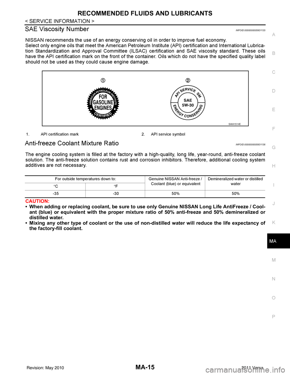
SAE Viscosity NumberINFOID:0000000005931135
NISSAN recommends the use of an energy conser ving oil in order to improve fuel economy.
Select only engine oils that meet the American Petroleum Institute (API) certification and International Lubrica-
tion Standardization and Approval Committee (ILSAC) ce rtification and SAE viscosity standard. These oils
have the API certification mark on the front of the container. Oils which do not have the specified quality label
should not be used as they could cause engine damage.
Anti-freeze Coolant Mixture RatioINFOID:0000000005931136
The engine cooling system is filled at the factory wit h a high-quality, long life, year-round, anti-freeze coolant
solution. The anti-freeze solution contains rust and corrosion inhibitors. Therefore, additional cooling system
additives are not necessary.
CAUTION:
• When adding or replacing coolant, be sure to u se only Genuine NISSAN Long Life AntiFreeze / Cool-
ant (blue) or equivalent with the proper mixture ratio of 50% an ti-freeze and 50% demineralized or
distilled water.
• Mixing any other type of coolant or the use of non-distilled water will reduce the life expectancy of
the factory-fi ll coolant.
SAIA1514E
1. API certification mark 2. API service symbol
For outside temperatures down to :Genuine NISSAN Anti-freeze /
Coolant (blue) or equivalent Demineralized water or distilled
water
° C °F
-35 -3050% 50%
Revision: May 2010 2011 Versa
Page 3193 of 3787
MA-22
< SERVICE INFORMATION >
ENGINE MAINTENANCE (HR16DE)
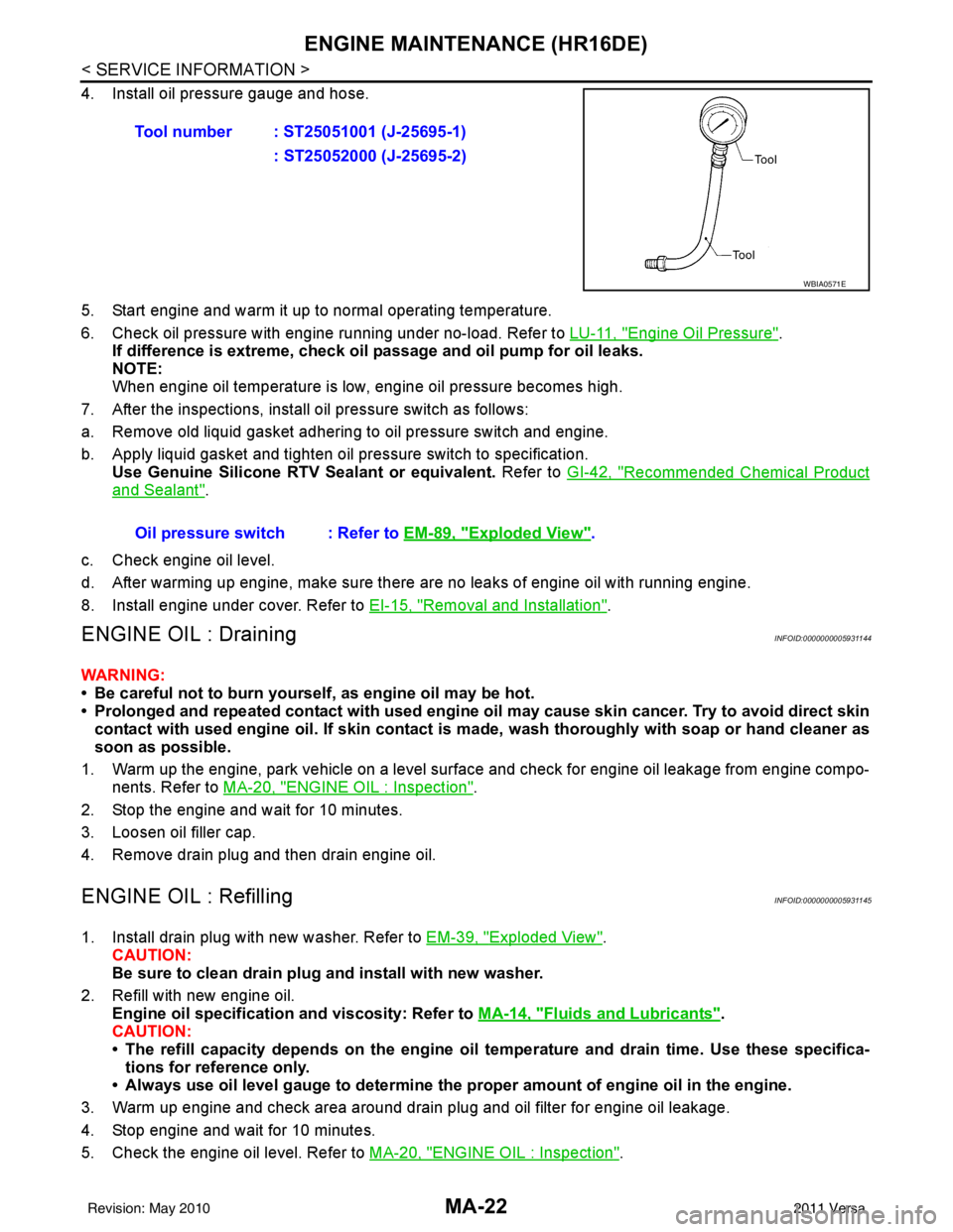
4. Install oil pressure gauge and hose.
5. Start engine and warm it up to normal operating temperature.
6. Check oil pressure with engine running under no-load. Refer to LU-11, "
Engine Oil Pressure".
If difference is extreme, check oil passage and oil pump for oil leaks.
NOTE:
When engine oil temperature is low, engine oil pressure becomes high.
7. After the inspections, install oil pressure switch as follows:
a. Remove old liquid gasket adhering to oil pressure switch and engine.
b. Apply liquid gasket and tighten oil pressure switch to specification. Use Genuine Silicone RTV Sealant or equivalent. Refer to GI-42, "
Recommended Chemical Product
and Sealant".
c. Check engine oil level.
d. After warming up engine, make sure there are no leaks of engine oil with running engine.
8. Install engine under cover. Refer to EI-15, "
Removal and Installation".
ENGINE OIL : DrainingINFOID:0000000005931144
WARNING:
• Be careful not to burn yourself, as engine oil may be hot.
• Prolonged and repeated contact with used engine oil may cause ski n cancer. Try to avoid direct skin
contact with used engine oil. If skin contact is made, wash thoroughly with soap or hand cleaner as
soon as possible.
1. Warm up the engine, park vehicle on a level surface and check for engine oil leakage from engine compo- nents. Refer to MA-20, "
ENGINE OIL : Inspection".
2. Stop the engine and wait for 10 minutes.
3. Loosen oil filler cap.
4. Remove drain plug and then drain engine oil.
ENGINE OIL : RefillingINFOID:0000000005931145
1. Install drain plug with new washer. Refer to EM-39, "Exploded View".
CAUTION:
Be sure to clean drain plug and install with new washer.
2. Refill with new engine oil. Engine oil specification and viscosity: Refer to MA-14, "
Fluids and Lubricants".
CAUTION:
• The refill capacity depends on the engine oi l temperature and drain time. Use these specifica-
tions for reference only.
• Always use oil level gauge to determine the pr oper amount of engine oil in the engine.
3. Warm up engine and check area around drain plug and oil filter for engine oil leakage.
4. Stop engine and wait for 10 minutes.
5. Check the engine oil level. Refer to MA-20, "
ENGINE OIL : Inspection".
Tool number : ST25051001 (J-25695-1)
: ST25052000 (J-25695-2)
WBIA0571E
Oil pressure switch : Refer to EM-89, "Exploded View".
Revision: May 2010 2011 Versa
Page 3203 of 3787
MA-32
< SERVICE INFORMATION >
ENGINE MAINTENANCE (MR18DE)
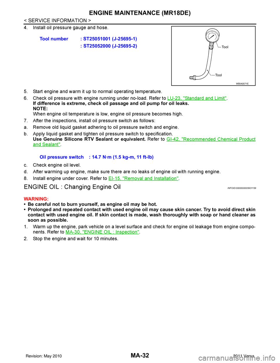
4. Install oil pressure gauge and hose.
5. Start engine and warm it up to normal operating temperature.
6. Check oil pressure with engine running under no-load. Refer to LU-23, "
Standard and Limit".
If difference is extreme, check oil passage and oil pump for oil leaks.
NOTE:
When engine oil temperature is low, engine oil pressure becomes high.
7. After the inspections, install oil pressure switch as follows:
a. Remove old liquid gasket adhering to oil pressure switch and engine.
b. Apply liquid gasket and tighten oil pressure switch to specification. Use Genuine Silicone RTV Sealant or equivalent. Refer to GI-42, "
Recommended Chemical Product
and Sealant".
c. Check engine oil level.
d. After warming up engine, make sure there are no leaks of engine oil with running engine.
8. Install engine under cover. Refer to EI-15, "
Removal and Installation".
ENGINE OIL : Changing Engine OilINFOID:0000000005931159
WARNING:
• Be careful not to burn yourself, as engine oil may be hot.
• Prolonged and repeated contact with used engine oil may cause ski n cancer. Try to avoid direct skin
contact with used engine oil. If skin contact is made, wash thoroughly with soap or hand cleaner as
soon as possible.
1. Warm up the engine, park vehicle on a level surface and check for engine oil leakage from engine compo- nents. Refer to MA-30, "
ENGINE OIL : Inspection".
2. Stop the engine and wait for 10 minutes. Tool number : ST25051001 (J-25695-1)
: ST25052000 (J-25695-2)
WBIA0571E
Oil pressure switch : 14.7 N·m (1.5 kg-m, 11 ft-lb)
Revision: May 2010 2011 Versa
Page 3204 of 3787
ENGINE MAINTENANCE (MR18DE)MA-33
< SERVICE INFORMATION >
C
DE
F
G H
I
J
K
M A
B
MA
N
O P
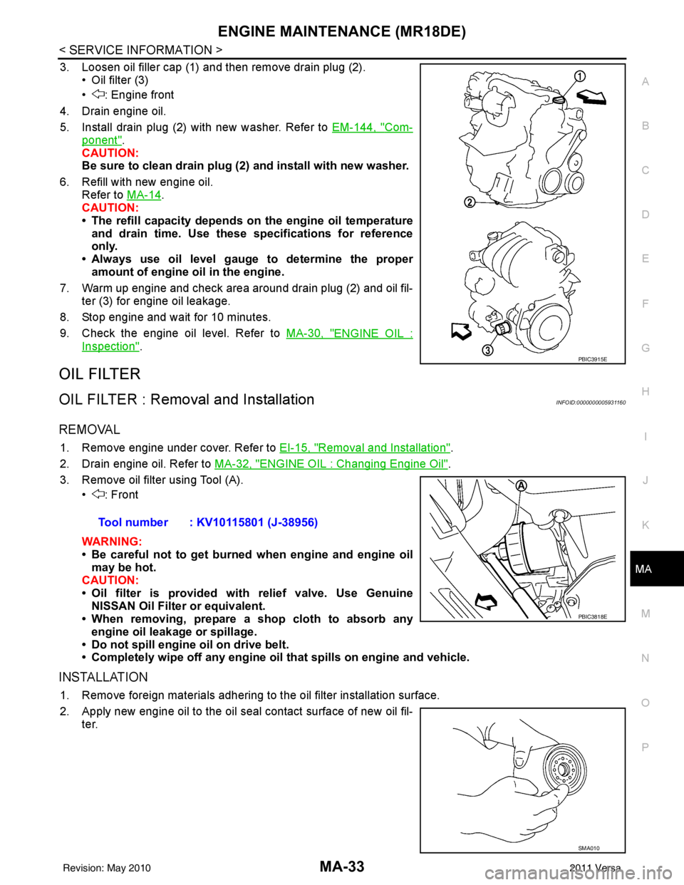
3. Loosen oil filler cap (1) and then remove drain plug (2). • Oil filter (3)
• : Engine front
4. Drain engine oil.
5. Install drain plug (2) with new washer. Refer to EM-144, "
Com-
ponent".
CAUTION:
Be sure to clean drain plug (2 ) and install with new washer.
6. Refill with new engine oil. Refer to MA-14
.
CAUTION:
• The refill capacity depends on the engine oil temperature
and drain time. Use these specifications for reference
only.
• Always use oil level gauge to determine the proper amount of engine oil in the engine.
7. Warm up engine and check area around drain plug (2) and oil fil- ter (3) for engine oil leakage.
8. Stop engine and wait for 10 minutes.
9. Check the engine oil level. Refer to MA-30, "
ENGINE OIL :
Inspection".
OIL FILTER
OIL FILTER : Removal and InstallationINFOID:0000000005931160
REMOVAL
1. Remove engine under cover. Refer to EI-15, "Removal and Installation".
2. Drain engine oil. Refer to MA-32, "
ENGINE OIL : Changing Engine Oil".
3. Remove oil filter using Tool (A). • : Front
WARNING:
• Be careful not to get burned when engine and engine oil
may be hot.
CAUTION:
• Oil filter is provided with relief valve. Use Genuine
NISSAN Oil Filter or equivalent.
• When removing, prepare a s hop cloth to absorb any
engine oil leakage or spillage.
• Do not spill engine oil on drive belt.
• Completely wipe off any engine oil that spills on engine and vehicle.
INSTALLATION
1. Remove foreign materials adhering to the oil filter installation surface.
2. Apply new engine oil to the oil seal contact surface of new oil fil-
ter.
PBIC3915E
Tool number : KV10115801 (J-38956)
PBIC3818E
SMA010
Revision: May 2010 2011 Versa
Page 3323 of 3787
PRECAUTIONSMTC-7
< SERVICE INFORMATION >
C
DE
F
G H
I
K L
M A
B
MTC
N
O P
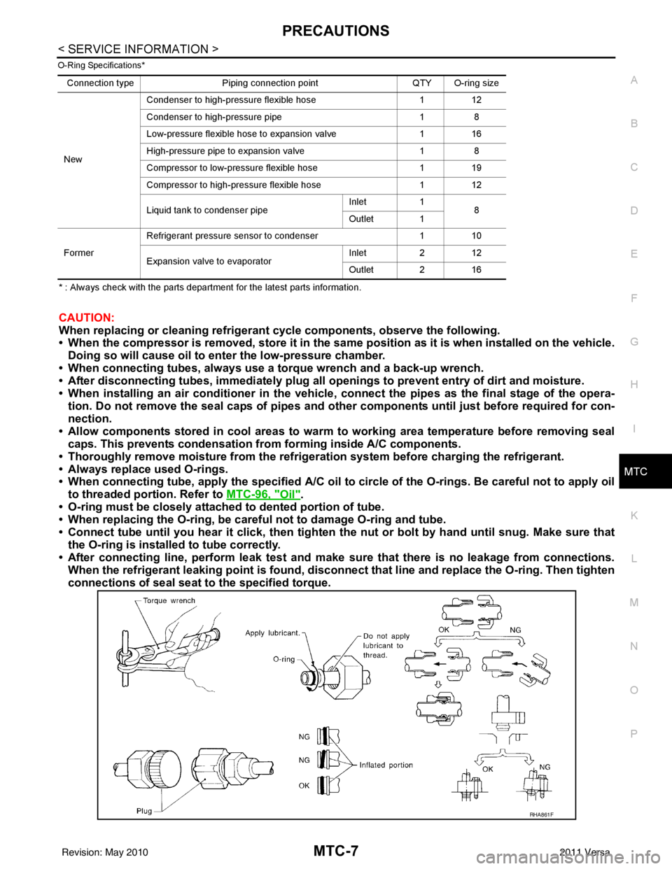
O-Ring Specifications*
* : Always check with the parts department for the latest parts information.
CAUTION:
When replacing or cleaning refrigerant cycle components, observe the following.
• When the compressor is removed, store it in the sam e position as it is when installed on the vehicle.
Doing so will cause oil to en ter the low-pressure chamber.
• When connecting tubes, always use a to rque wrench and a back-up wrench.
• After disconnecting tubes, immediately plug all op enings to prevent entry of dirt and moisture.
• When installing an air conditione r in the vehicle, connect the pipes as the final stage of the opera-
tion. Do not remove the seal caps of pipes and other components until just before required for con-
nection.
• Allow components stored in cool areas to warm to working area temperature before removing seal
caps. This prevents condensation from forming inside A/C components.
• Thoroughly remove moisture from the refrigeration system before charging the refrigerant.
• Always replace used O-rings.
• When connecting tube, apply the speci fied A/C oil to circle of the O-rings. Be careful not to apply oil
to threaded portion. Refer to MTC-96, "
Oil".
• O-ring must be closely attached to dented portion of tube.
• When replacing the O-ring, be careful not to damage O-ring and tube.
• Connect tube until you hear it cl ick, then tighten the nut or bolt by hand until snug. Make sure that
the O-ring is installed to tube correctly.
• After connecting line, perform leak test and make sure that there is no leakage from connections.
When the refrigerant leaking point is found, disconnect that line and replace the O-ring. Then tighten
connections of seal seat to the specified torque.
Connection type Piping connection point QTY O-ring size
New Condenser to high-pressure flexible hose
112
Condenser to high-pressure pipe 18
Low-pressure flexible hose to expansion valve 116
High-pressure pipe to expansion valve 18
Compressor to low-pressure flexible hose 119
Compressor to high-pressure flexible hose 112
Liquid tank to condenser pipe Inlet
1
8
Outlet 1
Former Refrigerant pressure sensor to condenser
110
Expansion valve to evaporator Inlet
212
Outlet 2 16
RHA861F
Revision: May 2010 2011 Versa
Page 3339 of 3787
TROUBLE DIAGNOSISMTC-23
< SERVICE INFORMATION >
C
DE
F
G H
I
K L
M A
B
MTC
N
O P
WORK SUPPORT
Display Item List
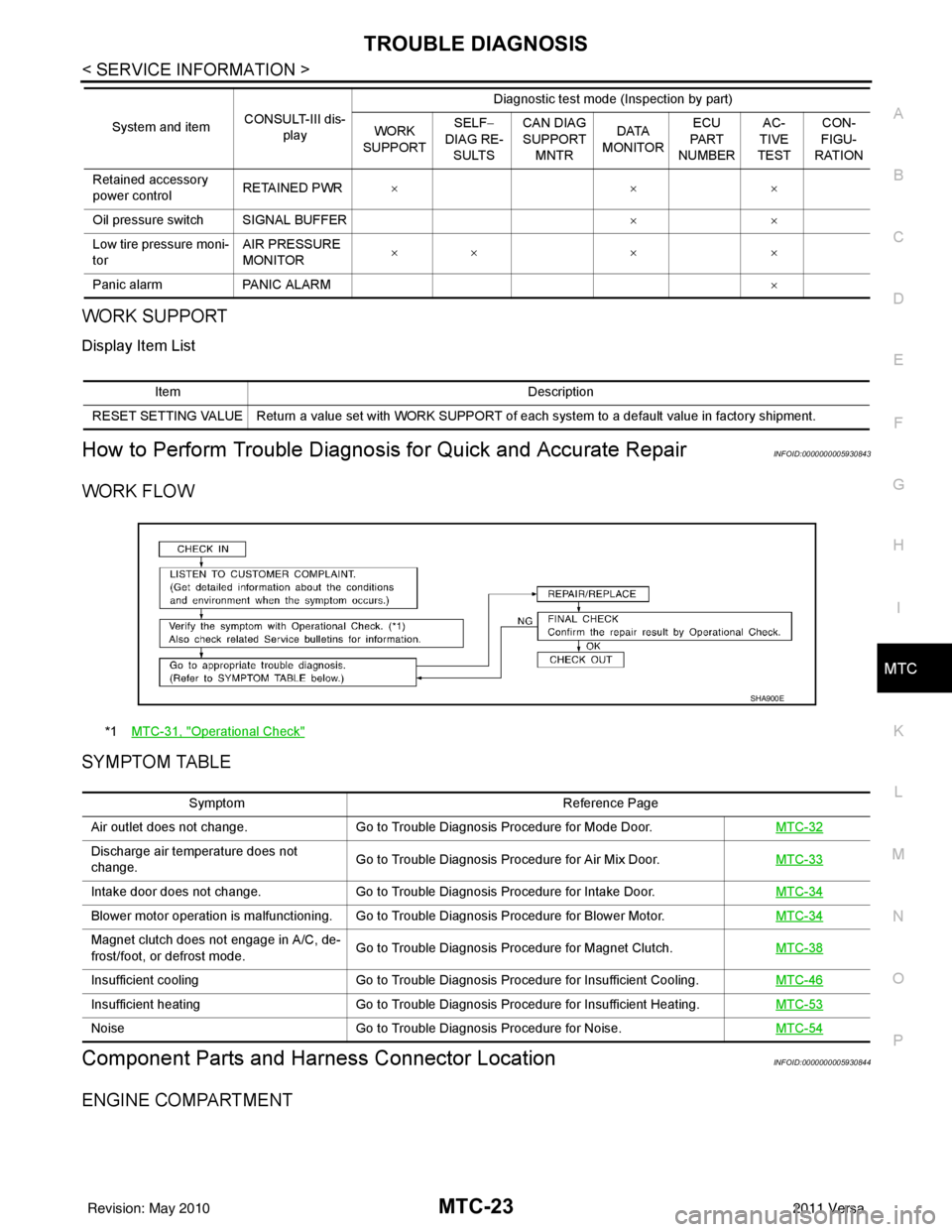
How to Perform Trouble Diagnosis for Quick and Accurate RepairINFOID:0000000005930843
WORK FLOW
SYMPTOM TABLE
Component Parts and Har ness Connector LocationINFOID:0000000005930844
ENGINE COMPARTMENT
Retained accessory
power controlRETAINED PWR
×× ×
Oil pressure switch SIGNAL BUFFER ××
Low tire pressure moni-
tor AIR PRESSURE
MONITOR
××
× ×
Panic alarm PANIC ALARM ×
System and item
CONSULT-III dis-
play Diagnostic test mode (Inspection by part)
WORK
SUPPORT SELF
−
DIAG RE-
SULTS CAN DIAG
SUPPORT
MNTR DATA
MONITOR ECU
PA R T
NUMBER AC-
TIVE
TEST CON-
FIGU-
RATION
Item Description
RESET SETTING VALUE Return a value set with WORK SUPPORT of each system to a default value in factory shipment.
*1 MTC-31, "Operational Check"
SHA900E
Symptom Reference Page
Air outlet does not change. Go to Trouble Diagnosis Procedure for Mode Door. MTC-32
Discharge air temperature does not
change.Go to Trouble Diagnosis Procedure for Air Mix Door.
MTC-33
Intake door does not change.Go to Trouble Diagnosis Procedure for Intake Door. MTC-34
Blower motor operation is malfunctioning. Go to Trouble Diagnosis Procedure for Blower Motor. MTC-34
Magnet clutch does not engage in A/C, de-
frost/foot, or defrost mode.Go to Trouble Diagnosis Procedure for Magnet Clutch.
MTC-38
Insufficient coolingGo to Trouble Diagnosis Procedure for Insufficient Cooling. MTC-46
Insufficient heatingGo to Trouble Diagnosis Procedure for Insufficient Heating. MTC-53
NoiseGo to Trouble Diagnosis Procedure for Noise. MTC-54
Revision: May 2010 2011 Versa
Page 3367 of 3787
TROUBLE DIAGNOSISMTC-51
< SERVICE INFORMATION >
C
DE
F
G H
I
K L
M A
B
MTC
N
O P
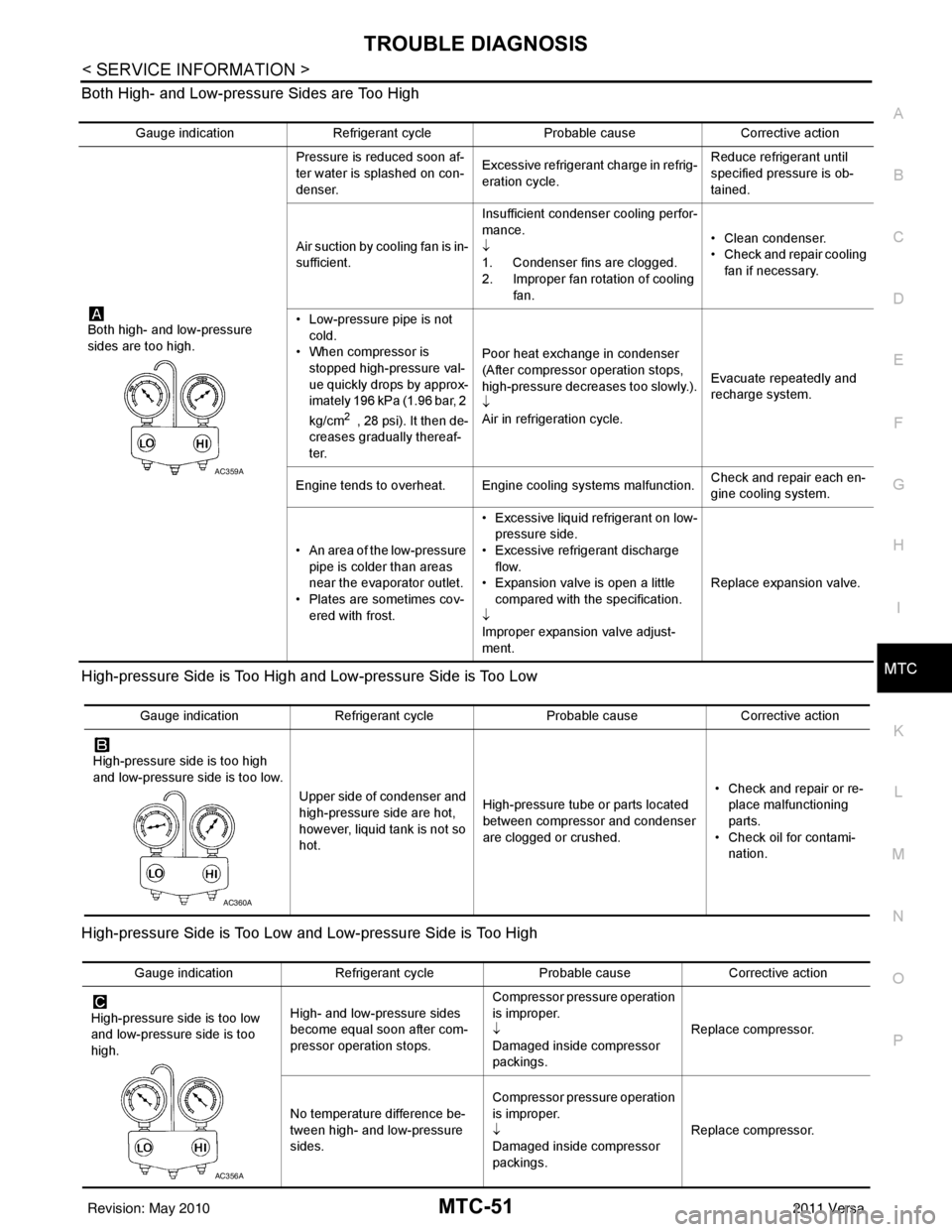
Both High- and Low-pressure Sides are Too High
High-pressure Side is Too High and Low-pressure Side is Too Low
High-pressure Side is Too Low and Low-pressure Side is Too High
Gauge indication
Refrigerant cycle Probable causeCorrective action
Both high- and low-pressure
sides are too high. Pressure is reduced soon af-
ter water is splashed on con-
denser.
Excessive refrigerant charge in refrig-
eration cycle. Reduce refrigerant until
specified pressure is ob-
tained.
Air suction by cooling fan is in-
sufficient. Insufficient condenser cooling perfor-
mance.
↓
1. Condenser fins are clogged.
2. Improper fan rotation of cooling
fan. • Clean condenser.
• Check and repair cooling
fan if necessary.
• Low-pressure pipe is not cold.
• When compressor is
stopped high-pressure val-
ue quickly drops by approx-
imately 196 kPa (1.96 bar, 2
kg/cm
2 , 28 psi). It then de-
creases gradually thereaf-
ter. Poor heat exchange in condenser
(After compressor operation stops,
high-pressure decreases too slowly.).
↓
Air in refrigeration cycle.
Evacuate repeatedly and
recharge system.
Engine tends to overheat. Engine cooling systems malfunction. Check and repair each en-
gine cooling system.
• An area of the low-pressure pipe is colder than areas
near the evaporator outlet.
• Plates are sometimes cov- ered with frost. • Excessive liquid refrigerant on low-
pressure side.
• Excessive refrigerant discharge flow.
• Expansion valve is open a little
compared with the specification.
↓
Improper expansion valve adjust-
ment. Replace expansion valve.
AC359A
Gauge indication
Refrigerant cycle Probable causeCorrective action
High-pressure side is too high
and low-pressure side is too low. Upper side of condenser and
high-pressure side are hot,
however, liquid tank is not so
hot.High-pressure tube or parts located
between compressor and condenser
are clogged or crushed. • Check and repair or re-
place malfunctioning
parts.
• Check oil for contami- nation.
AC360A
Gauge indication Refrigerant cycle Probable causeCorrective action
High-pressure side is too low
and low-pressure side is too
high. High- and low-pressure sides
become equal soon after com-
pressor operation stops. Compressor pressure operation
is improper.
↓
Damaged inside compressor
packings.
Replace compressor.
No temperature difference be-
tween high- and low-pressure
sides. Compressor pressure operation
is improper.
↓
Damaged inside compressor
packings.
Replace compressor.
AC356A
Revision: May 2010
2011 Versa