2011 NISSAN TIIDA cool fan diagnosis
[x] Cancel search: cool fan diagnosisPage 2858 of 3787
![NISSAN TIIDA 2011 Service Repair Manual LAN-12
< SERVICE INFORMATION >[CAN FUNDAMENTAL]
TROUBLE DIAGNOSIS
NOTE:
• When data link connector branch line is open, transmission and reception of CAN communication signals
are not affected. Ther](/manual-img/5/57396/w960_57396-2857.png "NISSAN TIIDA 2011 Service Repair Manual LAN-12
< SERVICE INFORMATION >[CAN FUNDAMENTAL]
TROUBLE DIAGNOSIS
NOTE:
• When data link connector branch line is open, transmission and reception of CAN communication signals
are not affected. Ther")
LAN-12
< SERVICE INFORMATION >[CAN FUNDAMENTAL]
TROUBLE DIAGNOSIS
NOTE:
• When data link connector branch line is open, transmission and reception of CAN communication signals
are not affected. Therefore, no symptoms occur. However, be sure to repair malfunctioning circuit.
• The model (all units on CAN communication system are Diag on CAN) cannot perform CAN diagnosis with
CONSULT-III if the following error occu rs. The error is judged by the symptom.
Example: Main Line Between Data Link Connector and ABS Actuator and Electric Un it (Control Unit) Open Circuit
Unit name Symptom
ECM
Normal operation.
BCM
EPS control unit
Combination meter
ABS actuator and electric unit (control unit)
TCM
IPDM E/R
Error Difference of symptom
Data link connector branch line open circuit Normal operation.
CAN-H, CAN-L harness short-circuit Most of the units which are connected to the CAN communication
system enter fail-safe mode or are deactivated.
SKIB8740E
Unit name
Symptom
ECM Engine torque limiting is affected, and shift harshness increases.
BCM • Reverse warning chime does not sound.
• The front wiper moves under continuous operation mode even though the front wip-
er switch being in the intermittent position.
EPS control unit The steering effort increases.
Combination meter • The shift position indicator and OD OFF indicator turn OFF.
• The speedometer is inoperative.
• The odo/trip meter stops.
ABS actuator and electric unit (control unit) Normal operation.
TCM No impact on operation.
IPDM E/R When the ignition switch is ON,
• The headlamps (Lo) turn ON.
• The cooling fan continues to rotate.
Revision: May 2010
2011 Versa
Page 2859 of 3787
![NISSAN TIIDA 2011 Service Repair Manual TROUBLE DIAGNOSISLAN-13
< SERVICE INFORMATION > [CAN FUNDAMENTAL]
C
D
E
F
G H
I
J
L
M A
B
LAN
N
O P
Example: CAN-H, CAN-L Harness Short Circuit
CAN Diagnosis with CONSULT-IIIINFOID:0000000005928521
CA](/manual-img/5/57396/w960_57396-2858.png "NISSAN TIIDA 2011 Service Repair Manual TROUBLE DIAGNOSISLAN-13
< SERVICE INFORMATION > [CAN FUNDAMENTAL]
C
D
E
F
G H
I
J
L
M A
B
LAN
N
O P
Example: CAN-H, CAN-L Harness Short Circuit
CAN Diagnosis with CONSULT-IIIINFOID:0000000005928521
CA")
TROUBLE DIAGNOSISLAN-13
< SERVICE INFORMATION > [CAN FUNDAMENTAL]
C
D
E
F
G H
I
J
L
M A
B
LAN
N
O P
Example: CAN-H, CAN-L Harness Short Circuit
CAN Diagnosis with CONSULT-IIIINFOID:0000000005928521
CAN diagnosis on CONSULT-III extracts the root
cause by receiving the following information.
• Response to the system call
• Control unit diagnosis information
• Self-diagnosis
• CAN diagnostic support monitor
SKIB8741E
Unit name Symptom
ECM • Engine torque limiting is affected, and shift harshness increases.
• Engine speed drops.
BCM • Reverse warning chime does not sound.
• The front wiper moves under continuous operation mode even though the front
wiper switch being in the intermittent position.
• The room lamp does not turn ON.
• The engine does not start (if an error or malfunction occurs while turning the igni- tion switch OFF.)
• The steering lock does not release (if an error or malfunction occurs while turning the ignition switch OFF.)
EPS control unit The steering effort increases.
Combination meter • The tachometer and the speedometer do not move.
• Warning lamps turn ON.
• Indicator lamps do not turn ON.
ABS actuator and electric unit (control unit) Normal operation.
TCM No impact on operation.
IPDM E/R When the ignition switch is ON,
• The headlamps (Lo) turn ON.
• The cooling fan continues to rotate.
Revision: May 2010
2011 Versa
Page 3317 of 3787

MTC-1
AIR CONDITIONER
C
DE
F
G H
I
K L
M
SECTION MTC
A
B
MTC
N
O P
CONTENTS
MANUAL AIR CONDITIONER
SERVICE INFORMATION .. ..........................3
PRECAUTIONS .............................................. .....3
Precaution for Supplemental Restraint System
(SRS) "AIR BAG" and "SEAT BELT PRE-TEN-
SIONER" ............................................................. ......
3
Precaution Necessary for Steering Wheel Rota-
tion After Battery Disconnect ............................... ......
3
Precaution for Procedure without Cowl Top Cover ......4
Precaution for Working with HFC-134a (R-134a) ......4
General Refrigerant Precaution ................................4
Oil Precaution ............................................................5
Precaution for Refrigerant Connection ......................5
Precaution for Service of Compressor ................ ......8
Precaution for Service Equipment ....................... ......8
Precaution for Leak Detection Dye ...........................9
PREPARATION ..................................................11
HFC-134a (R-134a) Service Tool and Equipment ....11
Commercial Service Tool ........................................14
REFRIGERATION SYSTEM ..............................15
Refrigerant Cycle ................................................ ....15
Refrigerant System Protection ................................15
Component Part Location ................................... ....16
OIL ......................................................................17
Maintenance of Oil Quantity in Compressor ....... ....17
AIR CONDITIONER CONTROL .........................19
Control Operation ................................................ ....19
Discharge Air Flow ..................................................20
System Description .................................................20
TROUBLE DIAGNOSIS .....................................22
CONSULT-III Function (BCM) ............................. ....22
How to Perform Trouble Diagnosis for Quick and
Accurate Repair ......................................................
23
Component Parts and Harness Connector Loca-
tion ...................................................................... ....
23
Schematic ...............................................................26
Wiring Diagram - Heater - .......................................27
Wiring Diagram - A/C,M - .................................... ....28
Operational Check ...................................................31
Mode Door ...............................................................32
Air Mix Door .............................................................33
Intake Door ..............................................................34
Front Blower Motor Circuit .......................................34
Magnet Clutch Circuit (If Equipped) ..................... ....38
Insufficient Cooling ..................................................46
Insufficient Heating ..................................................53
Noise .......................................................................54
CONTROLLER ..................................................56
Removal and Installation .........................................56
Disassembly and Assembly .....................................57
THERMO CONTROL AMPLIFIER ....................58
Removal and Installation .........................................58
A/C UNIT ASSEMBLY ......................................59
Removal and Installation .........................................59
Disassembly and Assembly .....................................61
BLOWER MOTOR ............................................63
Removal and Installation .........................................63
INTAKE DOOR ..................................................64
Intake Door Cable Adjustment .................................64
AIR MIX DOOR .................................................65
Air Mix Door Cable Adjustment ...............................65
MODE DOOR ....................................................66
Mode Door Cable Adjustment .................................66
BLOWER FAN RESISTOR ...............................67
Removal and Installation .........................................67
HEATER CORE .................................................68
Removal and Installation .........................................68
DUCTS AND GRILLES .....................................69
Removal and Installation .........................................69
Revision: May 2010 2011 Versa
Page 3348 of 3787
MTC-32
< SERVICE INFORMATION >
TROUBLE DIAGNOSIS
1. Turn blower control dial clockwise to "1" position. Blower should operate on low speed.
2. Turn blower control dial clockwise to "2" position, and continue checking blower speed until all speeds are
checked.
3. Leave blower on Maximum speed.
If NG, go to trouble diagnosis procedure for MTC-34, "
Front Blower Motor Circuit".
If OK, continue the check.
CHECKING DISCHARGE AIR
1. Turn mode door control dial to each position.
2. Confirm that discharge air comes out according to the air distribution table. Refer to MTC-20, "
Discharge
Air Flow".
If NG, go to trouble diagnosis procedure for MTC-32, "
Mode Door".
If OK, continue the check.
CHECKING RECIRCULATION
1. Set intake door lever to REC position.
2. Operate intake door lever to FRE position.
3. Listen for intake door position change (you should hear blower sound change slightly).
If NG, go to trouble diagnosis procedure for MTC-34, "
Intake Door".
If OK, continue the check.
CHECKING TEMPERATURE DECREASE
1. Turn temperature control dial counterclockwise to full cold position.
2. Check for cold air at discharge air outlets.
If NG, go to trouble diagnosis procedure for MTC-46, "
Insufficient Cooling".
If OK, continue the check.
CHECKING TEMPERATURE INCREASE
1. Turn temperature control dial clockwise to full hot position.
2. Check for hot air at discharge air outlets.
If NG, go to trouble diagnosis procedure for MTC-53, "
Insufficient Heating".
If OK, continue the check.
CHECKING A/C SWITCH (IF EQUIPPED)
1. Turn fan control dial to the desired (1 to 4 speed) position.
2. Press A/C switch.
3. A/C switch indicator will turn ON.
• Confirm that the compressor clutch engages (sound or visual inspection).
If NG, go to trouble diagnosis procedure for MTC-38, "
Magnet Clutch Circuit (If Equipped)".
If OK, continue the check.
CHECKING DEFROST A/C SWITCH (IF EQUIPPED)
1. Turn fan control dial to the desired (1 to 4 speed) position.
2. Turn mode dial to ( ) DEF.
3. Confirm that the compressor clutch engages (sound or visual inspection) and the A/C switch indicator illu- minates.
If NG, go to trouble diagnosis procedure for MTC-38, "
Magnet Clutch Circuit (If Equipped)".
If all operational checks are OK (symptom cannot be duplicated), go to MTC-23, "
How to Perform Trouble
Diagnosis for Quick and Accurate Repair" and perform tests as outlined. If symptom appears, refer to MTC-23,
"How to Perform Trouble Diagnosis for Quick and Accurate Repair" and perform applicable trouble diagnosis
procedures.
Mode DoorINFOID:0000000005930849
SYMPTOM: Air outlet does not change.
INSPECTION FLOW
Revision: May 2010 2011 Versa
Page 3354 of 3787
MTC-38
< SERVICE INFORMATION >
TROUBLE DIAGNOSIS
OK >> GO TO 11.
NG >> Repair harness or connector.
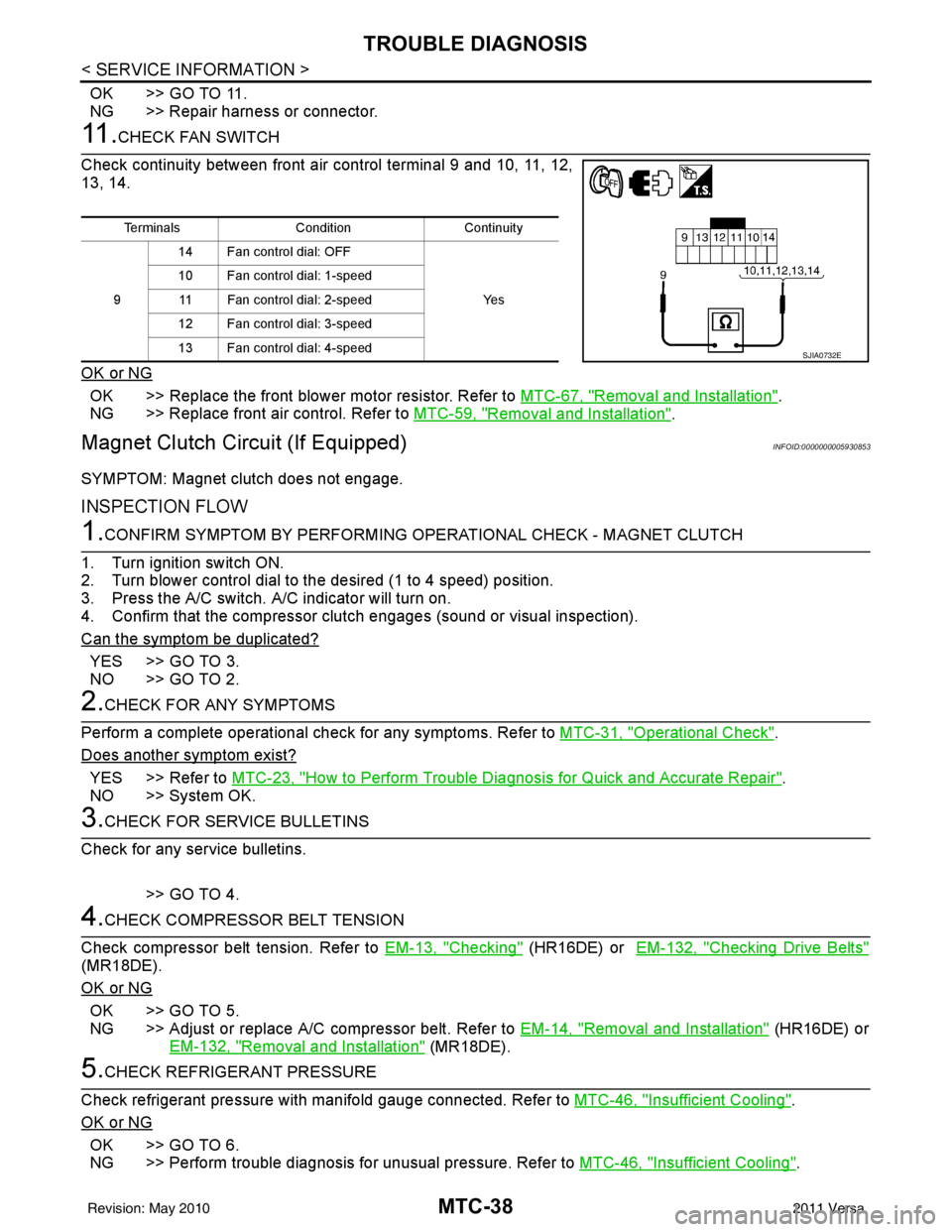
11 .CHECK FAN SWITCH
Check continuity between front air control terminal 9 and 10, 11, 12,
13, 14.
OK or NG
OK >> Replace the front blower motor resistor. Refer to MTC-67, "Removal and Installation".
NG >> Replace front air control. Refer to MTC-59, "
Removal and Installation".
Magnet Clutch Circuit (If Equipped)INFOID:0000000005930853
SYMPTOM: Magnet clutch does not engage.
INSPECTION FLOW
1.CONFIRM SYMPTOM BY PERFORMING OP ERATIONAL CHECK - MAGNET CLUTCH
1. Turn ignition switch ON.
2. Turn blower control dial to the desired (1 to 4 speed) position.
3. Press the A/C switch. A/C indicator will turn on.
4. Confirm that the compressor clut ch engages (sound or visual inspection).
Can the symptom be duplicated?
YES >> GO TO 3.
NO >> GO TO 2.
2.CHECK FOR ANY SYMPTOMS
Perform a complete operational check for any symptoms. Refer to MTC-31, "
Operational Check".
Does another symptom exist?
YES >> Refer to MTC-23, "How to Perform Trouble Diagnosis for Quick and Accurate Repair".
NO >> System OK.
3.CHECK FOR SERVICE BULLETINS
Check for any service bulletins.
>> GO TO 4.
4.CHECK COMPRESSOR BELT TENSION
Check compressor belt tension. Refer to EM-13, "
Checking" (HR16DE) or EM-132, "Checking Drive Belts"
(MR18DE).
OK or NG
OK >> GO TO 5.
NG >> Adjust or replace A/C compressor belt. Refer to EM-14, "
Removal and Installation" (HR16DE) or
EM-132, "
Removal and Installation" (MR18DE).
5.CHECK REFRIGERANT PRESSURE
Check refrigerant pressure with manifold gauge connected. Refer to MTC-46, "
Insufficient Cooling".
OK or NG
OK >> GO TO 6.
NG >> Perform trouble diagnosis for unusual pressure. Refer to MTC-46, "
Insufficient Cooling".
TerminalsConditionContinuity
9 14 Fan control dial: OFF
Ye s
10 Fan control dial: 1-speed
11 Fan control dial: 2-speed
12 Fan control dial: 3-speed
13 Fan control dial: 4-speed
SJIA0732E
Revision: May 2010 2011 Versa
Page 3362 of 3787
MTC-46
< SERVICE INFORMATION >
TROUBLE DIAGNOSIS
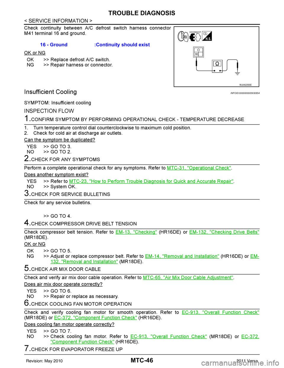
Check continuity between A/C defrost switch harness connector
M41 terminal 16 and ground.
OK or NG
OK >> Replace defrost A/C switch.
NG >> Repair harness or connector.
Insufficient CoolingINFOID:0000000005930854
SYMPTOM: Insufficient cooling
INSPECTION FLOW
1.CONFIRM SYMPTOM BY PERFORMING OPERATIONAL CHECK - TEMPERATURE DECREASE
1. Turn temperature control dial counterclockwise to maximum cold position.
2. Check for cold air at discharge air outlets.
Can the symptom be duplicated?
YES >> GO TO 3.
NO >> GO TO 2.
2.CHECK FOR ANY SYMPTOMS
Perform a complete operational check for any symptoms. Refer to MTC-31, "
Operational Check".
Does another symptom exist?
YES >> Refer to MTC-23, "How to Perform Trouble Diagnosis for Quick and Accurate Repair".
NO >> System OK.
3.CHECK FOR SERVICE BULLETINS
Check for any service bulletins.
>> GO TO 4.
4.CHECK COMPRESSOR DRIVE BELT TENSION
Check compressor belt tension. Refer to EM-13, "
Checking" (HR16DE) or EM-132, "Checking Drive Belts"
(MR18DE).
OK or NG
OK >> GO TO 5.
NG >> Adjust or replace compressor belt. Refer to EM-14, "
Removal and Installation" (HR16DE) or EM-
132, "Removal and Installation" (MR18DE).
5.CHECK AIR MIX DOOR CABLE
Check and verify air mix door cable operation. Refer to MTC-65, "
Air Mix Door Cable Adjustment".
Does air mix door operate correctly?
YES >> GO TO 6.
NO >> Repair or replace as necessary.
6.CHECK COOLING FAN MOTOR OPERATION
Check and verify cooling fan motor for smooth operation. Refer to EC-913, "
Overall Function Check"
(MR18DE) or EC-372, "Component Function Check" (HR16DE).
Does cooling fan motor operate correctly?
YES >> GO TO 7.
NO >> Check cooling fan motor. Refer to EC-913, "
Overall Function Check" (MR18DE) or EC-372,
"Component Function Check" (HR16DE).
7.CHECK FOR EVAPORATOR FREEZE UP16 - Ground :Continuity should exist
WJIA2255E
Revision: May 2010
2011 Versa
Page 3367 of 3787
TROUBLE DIAGNOSISMTC-51
< SERVICE INFORMATION >
C
DE
F
G H
I
K L
M A
B
MTC
N
O P
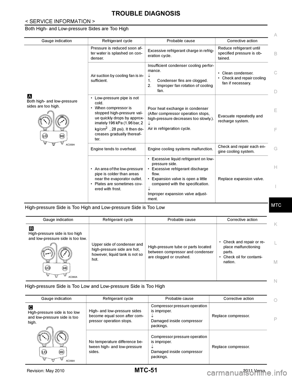
Both High- and Low-pressure Sides are Too High
High-pressure Side is Too High and Low-pressure Side is Too Low
High-pressure Side is Too Low and Low-pressure Side is Too High
Gauge indication
Refrigerant cycle Probable causeCorrective action
Both high- and low-pressure
sides are too high. Pressure is reduced soon af-
ter water is splashed on con-
denser.
Excessive refrigerant charge in refrig-
eration cycle. Reduce refrigerant until
specified pressure is ob-
tained.
Air suction by cooling fan is in-
sufficient. Insufficient condenser cooling perfor-
mance.
↓
1. Condenser fins are clogged.
2. Improper fan rotation of cooling
fan. • Clean condenser.
• Check and repair cooling
fan if necessary.
• Low-pressure pipe is not cold.
• When compressor is
stopped high-pressure val-
ue quickly drops by approx-
imately 196 kPa (1.96 bar, 2
kg/cm
2 , 28 psi). It then de-
creases gradually thereaf-
ter. Poor heat exchange in condenser
(After compressor operation stops,
high-pressure decreases too slowly.).
↓
Air in refrigeration cycle.
Evacuate repeatedly and
recharge system.
Engine tends to overheat. Engine cooling systems malfunction. Check and repair each en-
gine cooling system.
• An area of the low-pressure pipe is colder than areas
near the evaporator outlet.
• Plates are sometimes cov- ered with frost. • Excessive liquid refrigerant on low-
pressure side.
• Excessive refrigerant discharge flow.
• Expansion valve is open a little
compared with the specification.
↓
Improper expansion valve adjust-
ment. Replace expansion valve.
AC359A
Gauge indication
Refrigerant cycle Probable causeCorrective action
High-pressure side is too high
and low-pressure side is too low. Upper side of condenser and
high-pressure side are hot,
however, liquid tank is not so
hot.High-pressure tube or parts located
between compressor and condenser
are clogged or crushed. • Check and repair or re-
place malfunctioning
parts.
• Check oil for contami- nation.
AC360A
Gauge indication Refrigerant cycle Probable causeCorrective action
High-pressure side is too low
and low-pressure side is too
high. High- and low-pressure sides
become equal soon after com-
pressor operation stops. Compressor pressure operation
is improper.
↓
Damaged inside compressor
packings.
Replace compressor.
No temperature difference be-
tween high- and low-pressure
sides. Compressor pressure operation
is improper.
↓
Damaged inside compressor
packings.
Replace compressor.
AC356A
Revision: May 2010
2011 Versa
Page 3442 of 3787
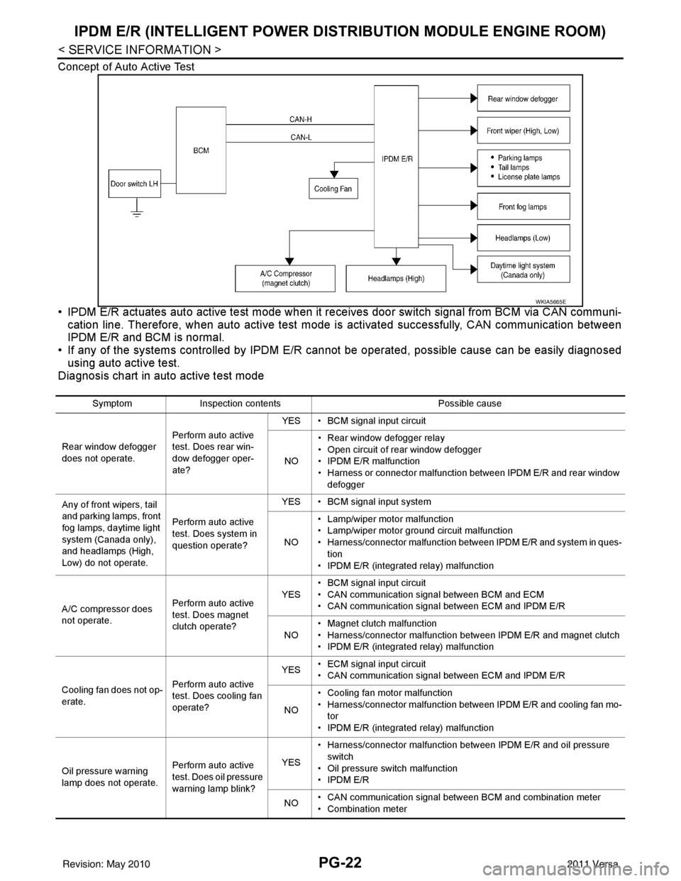
PG-22
< SERVICE INFORMATION >
IPDM E/R (INTELLIGENT POWER DISTRIBUTION MODULE ENGINE ROOM)
Concept of Auto Active Test
• IPDM E/R actuates auto active test mode when it re ceives door switch signal from BCM via CAN communi-
cation line. Therefore, when auto active test mode is activated successfully, CAN communication between
IPDM E/R and BCM is normal.
• If any of the systems controll ed by IPDM E/R cannot be operated, possible cause can be easily diagnosed
using auto active test.
Diagnosis chart in auto active test mode
WKIA5665E
Symptom Inspection contents Possible cause
Rear window defogger
does not operate. Perform auto active
test. Does rear win-
dow defogger oper-
ate?YES • BCM signal input circuit
NO • Rear window defogger relay
• Open circuit of rear window defogger
•IPDM E/R malfunction
• Harness or connector malfunction between IPDM E/R and rear window
defogger
Any of front wipers, tail
and parking lamps, front
fog lamps, daytime light
system (Canada only),
and headlamps (High,
Low) do not operate. Perform auto active
test. Does system in
question operate?YES • BCM signal input system
NO • Lamp/wiper motor malfunction
• Lamp/wiper motor ground circuit malfunction
• Harness/connector malfunction between IPDM E/R and system in ques-
tion
• IPDM E/R (integrated relay) malfunction
A/C compressor does
not operate. Perform auto active
test. Does magnet
clutch operate?YES
• BCM signal input circuit
• CAN communication signal between BCM and ECM
• CAN communication signal between ECM and IPDM E/R
NO • Magnet clutch malfunction
• Harness/connector malfunction between IPDM E/R and magnet clutch
• IPDM E/R (integrated relay) malfunction
Cooling fan does not op-
erate. Perform auto active
test. Does cooling fan
operate?YES
• ECM signal input circuit
• CAN communication signal between ECM and IPDM E/R
NO • Cooling fan motor malfunction
• Harness/connector malfunction between IPDM E/R and cooling fan mo-
tor
• IPDM E/R (integrated relay) malfunction
Oil pressure warning
lamp does not operate. Perform auto active
test. Does oil pressure
warning lamp blink?YES
• Harness/connector malfunction between IPDM E/R and oil pressure
switch
• Oil pressure switch malfunction
•IPDM E/R
NO • CAN communication signal between BCM and combination meter
• Combination meter
Revision: May 2010
2011 Versa