2011 NISSAN TIIDA air condition
[x] Cancel search: air conditionPage 555 of 3787
POWER DOOR LOCK SYSTEMBL-45
< SERVICE INFORMATION >
C
DE
F
G H
J
K L
M A
B
BL
N
O P
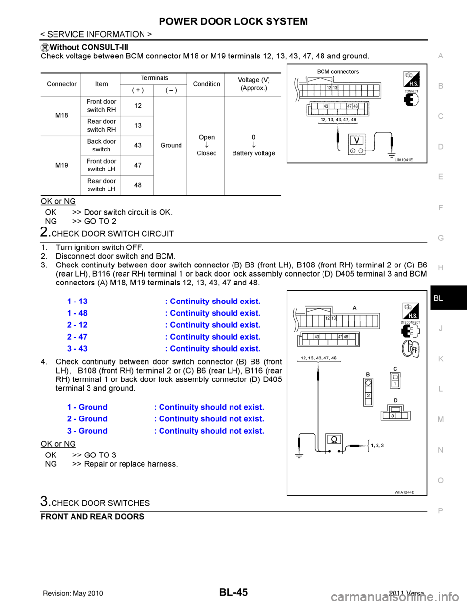
Without CONSULT-III
Check voltage between BCM connector M18 or M19 terminals 12, 13, 43, 47, 48 and ground.
OK or NG
OK >> Door switch circuit is OK.
NG >> GO TO 2
2.CHECK DOOR SWITCH CIRCUIT
1. Turn ignition switch OFF.
2. Disconnect door switch and BCM.
3. Check continuity between door switch connector (B) B8 (front LH), B108 (front RH) terminal 2 or (C) B6
(rear LH), B116 (rear RH) terminal 1 or back door lock assembly connector (D) D405 terminal 3 and BCM
connectors (A) M18, M19 te rminals 12, 13, 43, 47 and 48.
4. Check continuity between door switch connector (B) B8 (front LH), B108 (front RH) terminal 2 or (C) B6 (rear LH), B116 (rear
RH) terminal 1 or back door lo ck assembly connector (D) D405
terminal 3 and ground.
OK or NG
OK >> GO TO 3
NG >> Repair or replace harness.
3.CHECK DOOR SWITCHES
FRONT AND REAR DOORS
Connector Item Te r m i n a l s
ConditionVoltage (V)
(Approx.)
( + ) ( – )
M18 Front door
switch RH 12
Ground Open
↓
Closed 0
↓
Battery voltage
Rear door
switch RH 13
M19 Back door
switch 43
Front door switch LH 47
Rear door switch LH 48
LIIA1041E
1 - 13
: Continuity should exist.
1 - 48 : Continuity should exist.
2 - 12 : Continuity should exist.
2 - 47 : Continuity should exist.
3 - 43 : Continuity should exist.
1 - Ground : Continuity should not exist.
2 - Ground : Continuity should not exist.
3 - Ground : Continuity should not exist.
WIIA1244E
Revision: May 2010 2011 Versa
Page 558 of 3787
BL-48
< SERVICE INFORMATION >
POWER DOOR LOCK SYSTEM
OK or NG
OK >> GO TO 3
NG >> Repair or replace harness.
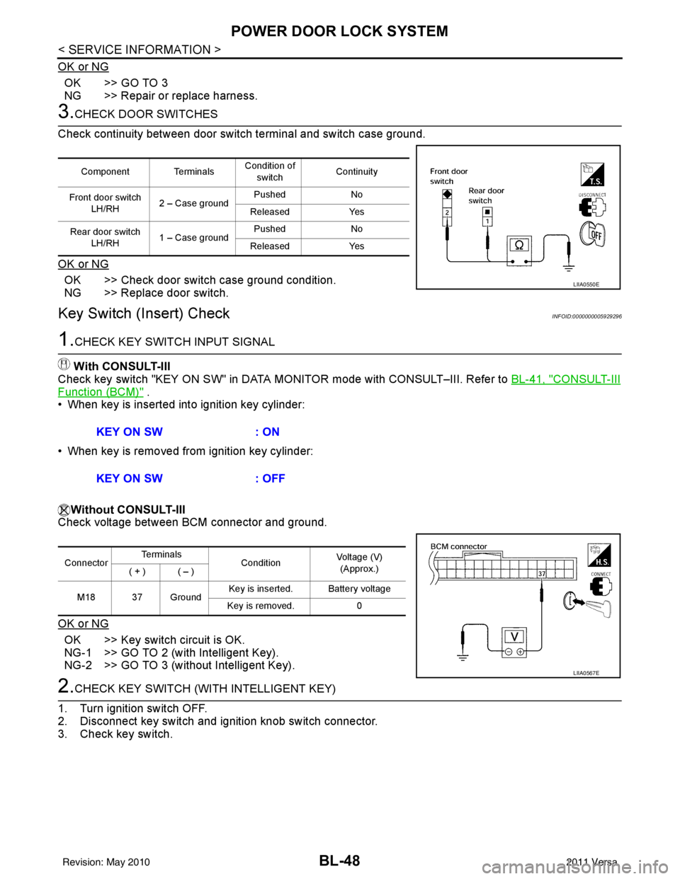
3.CHECK DOOR SWITCHES
Check continuity between door switch terminal and switch case ground.
OK or NG
OK >> Check door switch case ground condition.
NG >> Replace door switch.
Key Switch (I nsert) CheckINFOID:0000000005929296
1.CHECK KEY SWITCH INPUT SIGNAL
With CONSULT-III
Check key switch "KEY ON SW" in DATA MONITOR mode with CONSULT–III. Refer to BL-41, "
CONSULT-III
Function (BCM)" .
• When key is inserted into ignition key cylinder:
• When key is removed from ignition key cylinder:
Without CONSULT-III
Check voltage between BCM connector and ground.
OK or NG
OK >> Key switch circuit is OK.
NG-1 >> GO TO 2 (with Intelligent Key).
NG-2 >> GO TO 3 (without Intelligent Key).
2.CHECK KEY SWITCH (WITH INTELLIGENT KEY)
1. Turn ignition switch OFF.
2. Disconnect key switch and ignition knob switch connector.
3. Check key switch.
Component Terminals Condition of
switch Continuity
Front door switch LH/RH 2 – Case ground Pushed
No
Released Yes
Rear door switch LH/RH 1 – Case ground Pushed
No
Released Yes
LIIA0550E
KEY ON SW : ON
KEY ON SW : OFF
ConnectorTe r m i n a l s
ConditionVoltage (V)
(Approx.)
( + ) ( – )
M18 37 Ground Key is inserted. Battery voltage
Key is removed. 0
LIIA0567E
Revision: May 2010 2011 Versa
Page 563 of 3787
POWER DOOR LOCK SYSTEMBL-53
< SERVICE INFORMATION >
C
DE
F
G H
J
K L
M A
B
BL
N
O P
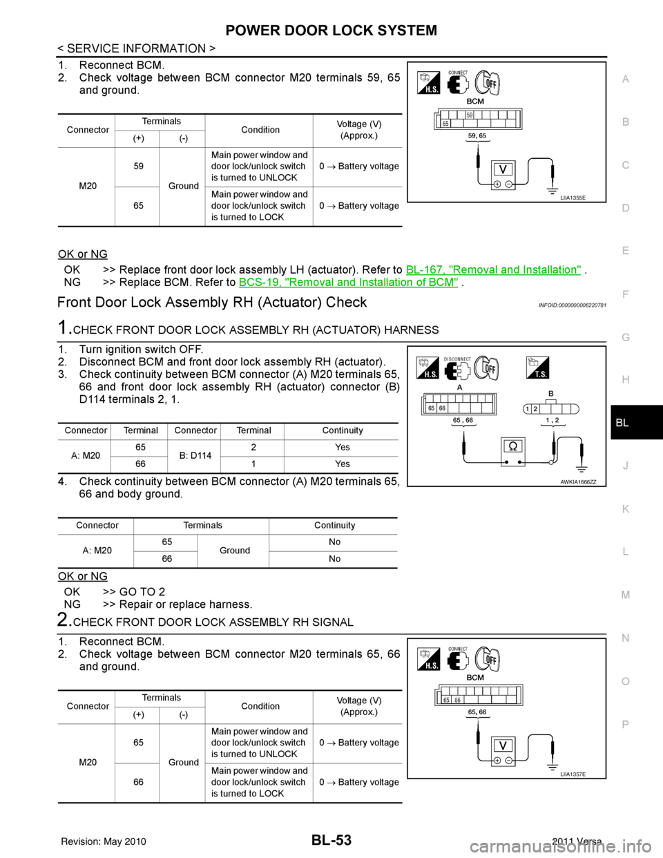
1. Reconnect BCM.
2. Check voltage between BCM connector M20 terminals 59, 65 and ground.
OK or NG
OK >> Replace front door lock assembly LH (actuator). Refer to BL-167, "Removal and Installation" .
NG >> Replace BCM. Refer to BCS-19, "
Removal and Installation of BCM" .
Front Door Lock Assembly RH (Actuator) CheckINFOID:0000000006220781
1.CHECK FRONT DOOR LOCK ASSEMBLY RH (ACTUATOR) HARNESS
1. Turn ignition switch OFF.
2. Disconnect BCM and front door lock assembly RH (actuator).
3. Check continuity between BCM connector (A) M20 terminals 65, 66 and front door lock assembly RH (actuator) connector (B)
D114 terminals 2, 1.
4. Check continuity between BCM connector (A) M20 terminals 65, 66 and body ground.
OK or NG
OK >> GO TO 2
NG >> Repair or replace harness.
2.CHECK FRONT DOOR LOCK ASSEMBLY RH SIGNAL
1. Reconnect BCM.
2. Check voltage between BCM connector M20 terminals 65, 66 and ground.
Connector Te r m i n a l s
ConditionVoltage (V)
(Approx.)
(+) (-)
M20 59
Ground Main power window and
door lock/unlock switch
is turned to UNLOCK
0
→ Battery voltage
65 Main power window and
door lock/unlock switch
is turned to LOCK 0
→ Battery voltage
LIIA1355E
Connector Terminal Connector Terminal Continuity
A: M20 65
B: D114 2Y
es
66 1Yes
Connector Terminals Continuity
A: M20 65
Ground No
66 No
AWKIA1666ZZ
ConnectorTe r m i n a l s
ConditionVoltage (V)
(Approx.)
(+) (-)
M20 65
Ground Main power window and
door lock/unlock switch
is turned to UNLOCK
0
→ Battery voltage
66 Main power window and
door lock/unlock switch
is turned to LOCK
0
→ Battery voltage
LIIA1357E
Revision: May 2010 2011 Versa
Page 564 of 3787

BL-54
< SERVICE INFORMATION >
POWER DOOR LOCK SYSTEM
OK or NG
OK >> Replace front door lock assembly RH (actuator). Refer to BL-167, "Removal and Installation" .
NG >> Replace BCM. Refer to BCS-19, "
Removal and Installation of BCM" .
Rear Door Lock Actuator LH/RH CheckINFOID:0000000005929299
1.CHECK DOOR LOCK ACTUATOR HARNESS
NOTE:
For models with Intelligent Key, insure that passenger select unlock relay remains connected during this test.
1. Turn ignition switch OFF.
2. Disconnect BCM and each door lock actuator.
3. Check continuity between BCM connector (A) M20 terminals 65, 66 and rear door lock actuator RH connector (B) D305, rear
door lock actuator LH connector (C) D205 terminals 2, 3.
4. Check continuity between BCM connector (A) M20 terminals 65, 66 and body ground.
OK or NG
OK >> GO TO 2
NG >> Check the following: • Without Intelligent Key: Repair or replace harness.
• With Intelligent Key: Repair or replace harness or pas-senger select unlock relay.
2.CHECK DOOR LOCK ACTUATOR SIGNAL
1. Reconnect BCM.
2. Check voltage between BCM connector M20 terminals 65, 66 and ground.
OK or NG
OK >> Replace rear door lock actuator LH/RH. Refer to BL-170, "Removal and Installation" .
NG >> Replace BCM. Refer to BCS-19, "
Removal and Installation of BCM" .
Front Door Lock Assembly LH (Key Cylinder Switch) CheckINFOID:0000000005929300
1.CHECK FRONT DOOR LOCK ASSEMB LY LH (KEY CYLINDER SWITCH)
With CONSULT-III
Connector Terminal Connector Terminal Continuity
A: M20 65
B: D305
C: D205 3Y
es
66 2Yes
Connector Terminals Continuity
A: M20 65
Ground No
66 No
LIIA2526E
ConnectorTe r m i n a l s
ConditionVoltage (V)
(Approx.)
(+) (-)
M20 65
Ground Main power window and
door lock/unlock switch is
turned to UNLOCK
0
→ Battery voltage
66 Main power window and
door lock/unlock switch is
turned to LOCK 0
→ Battery voltage
LIIA1357E
Revision: May 2010 2011 Versa
Page 565 of 3787
POWER DOOR LOCK SYSTEMBL-55
< SERVICE INFORMATION >
C
DE
F
G H
J
K L
M A
B
BL
N
O P
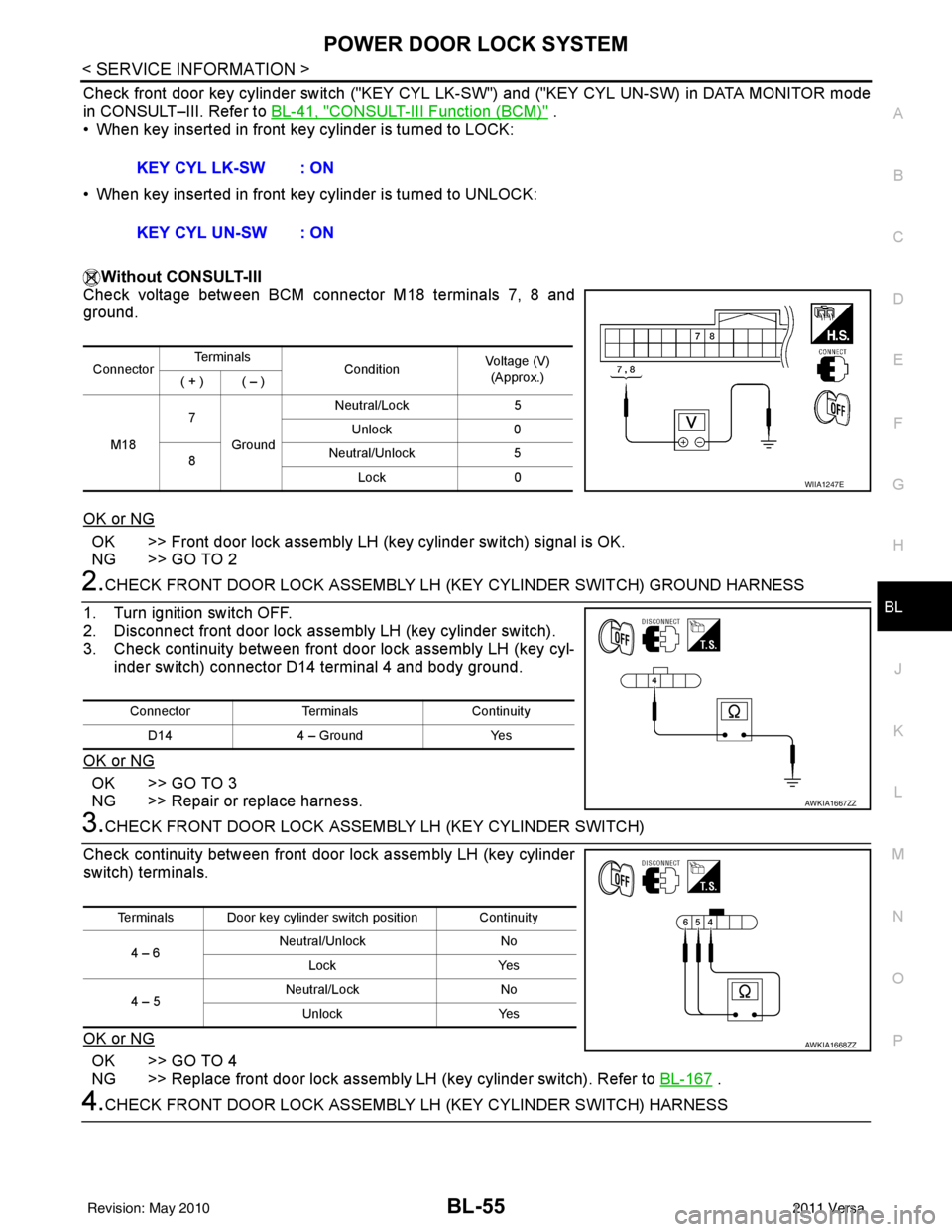
Check front door key cylinder switch ("KEY CYL LK -SW") and ("KEY CYL UN-SW) in DATA MONITOR mode
in CONSULT–III. Refer to BL-41, "
CONSULT-III Function (BCM)" .
• When key inserted in front key cylinder is turned to LOCK:
• When key inserted in front key cylinder is turned to UNLOCK:
Without CONSULT-III
Check voltage between BCM connector M18 terminals 7, 8 and
ground.
OK or NG
OK >> Front door lock assembly LH (key cylinder switch) signal is OK.
NG >> GO TO 2
2.CHECK FRONT DOOR LOCK ASSEMBLY LH (KEY CYLINDER SWITCH) GROUND HARNESS
1. Turn ignition switch OFF.
2. Disconnect front door lock assembly LH (key cylinder switch).
3. Check continuity between front door lock assembly LH (key cyl- inder switch) connector D14 terminal 4 and body ground.
OK or NG
OK >> GO TO 3
NG >> Repair or replace harness.
3.CHECK FRONT DOOR LOCK ASSEM BLY LH (KEY CYLINDER SWITCH)
Check continuity between front door lock assembly LH (key cylinder
switch) terminals.
OK or NG
OK >> GO TO 4
NG >> Replace front door lock assembly LH (key cylinder switch). Refer to BL-167
.
4.CHECK FRONT DOOR LOCK ASSEMBLY LH (KEY CYLINDER SWITCH) HARNESS
KEY CYL LK-SW : ON
KEY CYL UN-SW : ON
Connector
Te r m i n a l s
ConditionVoltage (V)
(Approx.)
( + ) ( – )
M18 7
Ground Neutral/Lock
5
Unlock 0
8 Neutral/Unlock
5
Lock 0
WIIA1247E
Connector TerminalsContinuity
D14 4 – Ground Yes
AWKIA1667ZZ
Terminals Door key cylinder switch position Continuity
4 – 6 Neutral/Unlock
No
Lock Yes
4 – 5 Neutral/Lock
No
Unlock Yes
AWKIA1668ZZ
Revision: May 2010 2011 Versa
Page 567 of 3787

POWER DOOR LOCK SYSTEMBL-57
< SERVICE INFORMATION >
C
DE
F
G H
J
K L
M A
B
BL
N
O P
1. Check continuity between passenger select unlock relay con- nector (A) M2 terminal 4 and rear door lock actuator LH connec-
tor (B) D205 or rear door lock actuator RH connector (C) D305
terminal 3.
2. Check continuity between passenger select unlock relay con- nector (A) M2 terminal 4 and ground.
OK or NG
OK >> Replace passenger select unlock relay.
NG >> Repair or replace harness between relay and actuator.
4.CHECK REAR DOOR LOCK ACTUATOR ASSEMBLY
1. Reconnect BCM.
2. Check voltage between rear door lock actuator connector LH (A) D205 or rear door lock actuator connector RH (B) D305 termi-
nals 2 and 3.
3. Check voltage between rear door lock actuator connector LH (A) D205 or rear door lock actuator connector RH (B) D305 termi-
nals 2 and 3.
OK or NG
OK >> Replace rear door lock actuator. Refer to BL-170, "Removal and Installation" .
NG >> Repair or replace harness between actuator and splice. 4 - 3
: Continuity should exist.
4 - Ground : Continuity should not exist.
WIIA1166E
ConnectorTe r m i n a l s
Condition Voltage (V)
(Approx.)
(+) (-)
A: D205 (LH)
B: D305 (RH) 32Main power window and
door lock/unlock switch is
turned to LOCK 0
→ Battery voltage
WIIA1167E
Connector Te r m i n a l s
Condition Voltage (V)
(Approx.)
(+) (-)
A: D205 (LH)
B: D305 (RH) 23Main power window and
door lock/unlock switch is
turned to UNLOCK 0
→ Battery voltage
WIIA1216E
Revision: May 2010 2011 Versa
Page 579 of 3787
REMOTE KEYLESS ENTRY SYSTEMBL-69
< SERVICE INFORMATION >
C
DE
F
G H
J
K L
M A
B
BL
N
O P
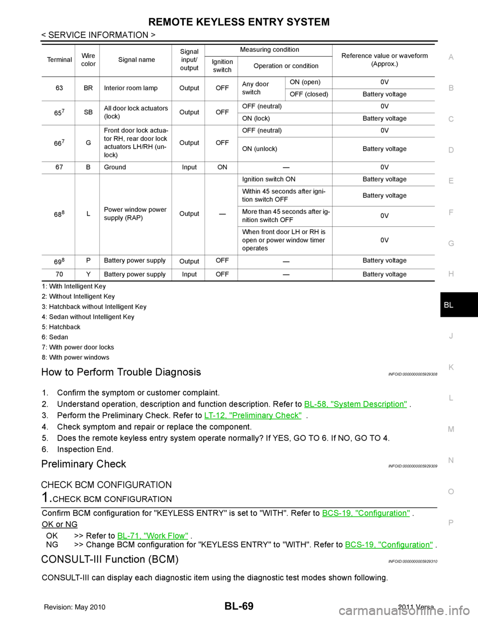
1: With Intelligent Key
2: Without Intelligent Key
3: Hatchback without Intelligent Key
4: Sedan without Intelligent Key
5: Hatchback
6: Sedan
7: With power door locks
8: With power windows
How to Perform Trouble DiagnosisINFOID:0000000005929308
1. Confirm the symptom or customer complaint.
2. Understand operation, description and function description. Refer to BL-58, "
System Description" .
3. Perform the Preliminary Check. Refer to LT-12, "
Preliminary Check" .
4. Check symptom and repair or replace the component.
5. Does the remote keyless entry system operate normally? If YES, GO TO 6. If NO, GO TO 4.
6. Inspection End.
Preliminary CheckINFOID:0000000005929309
CHECK BCM CONFIGURATION
1.CHECK BCM CONFIGURATION
Confirm BCM configuration for "KEYLESS ENTRY" is set to "WITH". Refer to BCS-19, "
Configuration" .
OK or NG
OK >> Refer to BL-71, "Work Flow" .
NG >> Change BCM configuration for "KEYLESS ENTRY" to "WITH". Refer to BCS-19, "
Configuration" .
CONSULT-III Function (BCM)INFOID:0000000005929310
CONSULT-III can display each diagnostic item using the diagnostic test modes shown following.
63 BR Interior room lamp Output OFFAny door
switchON (open)
0V
OFF (closed) Battery voltage
65
7SB All door lock actuators
(lock) Output OFFOFF (neutral)
0V
ON (lock) Battery voltage
66
7G Front door lock actua-
tor RH, rear door lock
actuators LH/RH (un-
lock) Output OFFOFF (neutral)
0V
ON (unlock) Battery voltage
67 B Ground Input ON—0V
68
8L Power window power
supply (RAP)
Output —Ignition switch ON
Battery voltage
Within 45 seconds after igni-
tion switch OFF Battery voltage
More than 45 seconds after ig-
nition switch OFF 0V
When front door LH or RH is
open or power window timer
operates 0V
69
8P Battery power supply OutputOFF
— Battery voltage
70 Y Battery power supply Input OFF —Battery voltage
Te r m i n a l
Wire
color Signal name Signal
input/
output Measuring condition
Reference value or waveform
(Approx.)
Ignition
switch Operation or condition
Revision: May 2010
2011 Versa
Page 581 of 3787
REMOTE KEYLESS ENTRY SYSTEMBL-71
< SERVICE INFORMATION >
C
DE
F
G H
J
K L
M A
B
BL
N
O P
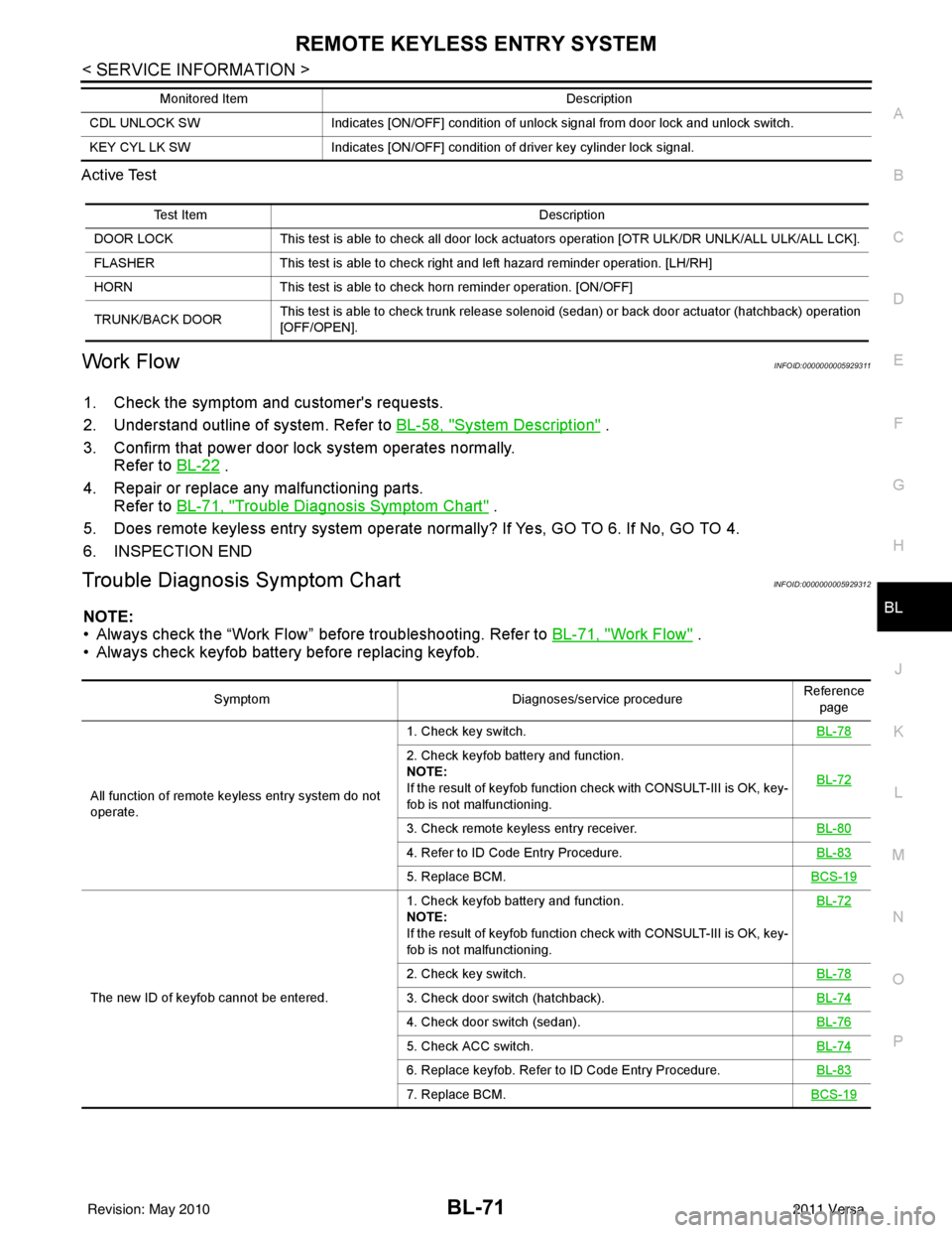
Active Test
Work FlowINFOID:0000000005929311
1. Check the symptom and customer's requests.
2. Understand outline of system. Refer to
BL-58, "
System Description" .
3. Confirm that power door lock system operates normally. Refer to BL-22
.
4. Repair or replace any malfunctioning parts. Refer to BL-71, "
Trouble Diagnosis Symptom Chart" .
5. Does remote keyless entry system operate normally? If Yes, GO TO 6. If No, GO TO 4.
6. INSPECTION END
Trouble Diagnosis Symptom ChartINFOID:0000000005929312
NOTE:
• Always check the “Work Flow” before troubleshooting. Refer to BL-71, "
Work Flow" .
• Always check keyfob battery before replacing keyfob.
CDL UNLOCK SW Indicates [ON/OFF] condition of unlock signal from door lock and unlock switch.
KEY CYL LK SW Indicates [ON/OFF] condition of driver key cylinder lock signal.
Monitored Item
Description
Test ItemDescription
DOOR LOCK This test is able to check all door lock actuators operation [OTR ULK/DR UNLK/ALL ULK/ALL LCK].
FLASHER This test is able to check right and left hazard reminder operation. [LH/RH]
HORN This test is able to check horn reminder operation. [ON/OFF]
TRUNK/BACK DOOR This test is able to check trunk release solenoid (sedan) or back door actuator (hatchback) operation
[OFF/OPEN].
Symptom
Diagnoses/service procedureReference
page
All function of remote keyless entry system do not
operate. 1. Check key switch.
BL-78
2. Check keyfob battery and function.
NOTE:
If the result of keyfob function check with CONSULT-III is OK, key-
fob is not malfunctioning.BL-72
3. Check remote keyless entry receiver.
BL-80
4. Refer to ID Code Entry Procedure.BL-83
5. Replace BCM.BCS-19
The new ID of keyfob cannot be entered.1. Check keyfob battery and function.
NOTE:
If the result of keyfob function check with CONSULT-III is OK, key-
fob is not malfunctioning.
BL-72
2. Check key switch.
BL-78
3. Check door switch (hatchback).BL-74
4. Check door switch (sedan).BL-76
5. Check ACC switch.BL-74
6. Replace keyfob. Refer to ID Code Entry Procedure.BL-83
7. Replace BCM.BCS-19
Revision: May 2010 2011 Versa