2011 NISSAN TIIDA hood
[x] Cancel search: hoodPage 2353 of 3787

FRONT GRILLEEI-23
< ON-VEHICLE REPAIR >
C
DE
F
G H
J
K L
M A
B
EI
N
O P
FRONT GRILLE
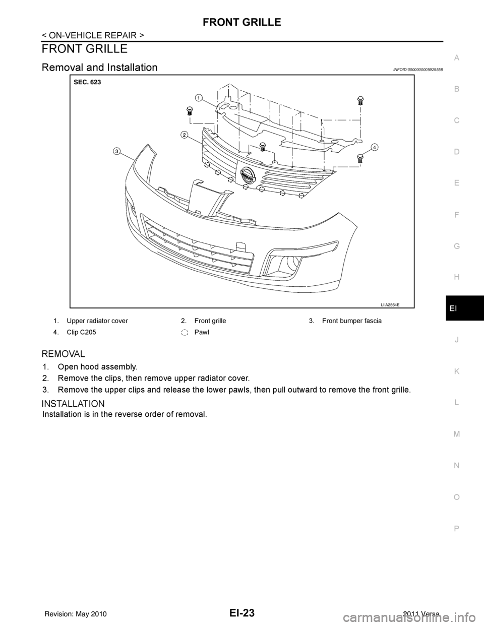
Removal and InstallationINFOID:0000000005929558
REMOVAL
1. Open hood assembly.
2. Remove the clips, then remove upper radiator cover.
3. Remove the upper clips and release the lower pawls, then pull outward to remove the front grille.
INSTALLATION
Installation is in the reverse order of removal.
LIIA2564E
1. Upper radiator cover2. Front grille3. Front bumper fascia
4. Clip C205 Pawl
Revision: May 2010 2011 Versa
Page 2473 of 3787
![NISSAN TIIDA 2011 Service Repair Manual ENGINE ASSEMBLYEM-83
< REMOVAL AND INSTALLATION > [HR16DE]
C
D
E
F
G H
I
J
K L
M A
EM
NP
O
• If items or work required are not covered by the engine section, follow the procedures in the applica-
bl NISSAN TIIDA 2011 Service Repair Manual ENGINE ASSEMBLYEM-83
< REMOVAL AND INSTALLATION > [HR16DE]
C
D
E
F
G H
I
J
K L
M A
EM
NP
O
• If items or work required are not covered by the engine section, follow the procedures in the applica-
bl](/manual-img/5/57396/w960_57396-2472.png)
ENGINE ASSEMBLYEM-83
< REMOVAL AND INSTALLATION > [HR16DE]
C
D
E
F
G H
I
J
K L
M A
EM
NP
O
• If items or work required are not covered by the engine section, follow the procedures in the applica-
ble sections.
• Always use the support poin t specified for lifting.
• Use either 2-pole lift type or separate type lift as best you can. If board-on type is used for unavoid-
able reasons, support at the rear axle jacking point with a transmission jack or similar tool before
starting work, in preparation for the backward shif t of center of gravity.
• For supporting points fo r lifting and jacking point at rear axle, refer to GI-38, "
Garage Jack and
Safety Stand and 2-Pole Lift".
REMOVAL
Outline
Remove the engine and the transaxle assembly from t he vehicle downward. Separate the engine and the tran-
saxle.
Preparation
1. Remove the hood assembly. Refer to BL-14, "Removal and Installation".
2. Remove the cowl top cover and cowl top extension assembly. Refer to EI-24, "
Removal and Installation".
3. Release fuel pressure. Refer to EC-499, "
Inspection".
4. Drain engine coolant from radiator. Refer to CO-11, "
Changing Engine Coolant".
CAUTION:
• Perform this step when the engine is cold.
• Never spill engine coolant on drive belt.
5. Remove the following parts. • Engine under cover. Refer to EI-15, "
Removal and Installation".
• Front road wheels and tires. Refer to WT-7, "
Adjustment".
• Front fender protector (RH and LH). Refer to EI-26, "
Removal and Installation".
• Battery and battery tray. Refer to SC-7, "
Removal and Installation".
• Drive belt. Refer to EM-14, "
Removal and Installation".
• Air duct and air cleaner case assembly. Refer to EM-25, "
Exploded View".
• Radiator hose (upper and lower). Refer to CO-16, "
Component".
• Disconnect cooling fan controller wiring harness.
• Remove coolant reservoir tank.
• Remove fan shroud and cooling fan assembly. Refer to CO-18, "
Component (Models with A/C)" or CO-
18, "Component (Models without A/C)".
Engine Room LH
1. Disconnect all connections of engine harness around the engine mounting insulator (LH), and then tem-
porarily secure the engine harness into the engine side.
CAUTION:
Protect connectors using a resin bag against foreign materials.
2. Remove ground cable at transaxle side.
3. Disconnect fuel feed hose at engine side. Refer to EM-33, "
Exploded View".
4. Disconnect EVAP purge hose and brake booster vacuum hose.
5. Disconnect heater hoses, and install plugs them to prevent engine coolant from draining. Refer to CO-16,
"Component".
6. Disconnect control linkage from transaxle. Refer to AT-213, "
A/T Shift Selector Removal and Installation"
(A/T), MT-14, "Exploded View" (M/T).
7. Disconnect the clutch tube at tr ansmission side (if equipped). Refer to CL-15, "
Removal and Installation".
Engine Room RH
1. Remove ground cable between front cover and vehicle.
2. Remove generator and generator br acket (A/C models). Refer to SC-25, "
Removal and Installation".
3. Remove A/C compressor with piping connected from t he engine. Temporarily secure it on the vehicle side
with a rope to avoid putting load on it (if equipped). Refer to MTC-78, "
Removal and Installation of Com-
pressor - HR16DE".
Vehicle Underbody
1. Remove front wheel sensor (LH and RH) for ABS from steering knuckle (if equipped). Refer to BRC-33,
"Removal and Installation" (ABS) or BRC-86, "Removal and Installation" (VDC/TCS/ABS).
Revision: May 2010 2011 Versa
Page 2588 of 3787
![NISSAN TIIDA 2011 Service Repair Manual EM-198
< SERVICE INFORMATION >[MR18DE]
ENGINE ASSEMBLY
• Use either 2-pole lift type or separate type lift as
best you can. If board-on type is used for unavoid-
able reasons, support at the rear a NISSAN TIIDA 2011 Service Repair Manual EM-198
< SERVICE INFORMATION >[MR18DE]
ENGINE ASSEMBLY
• Use either 2-pole lift type or separate type lift as
best you can. If board-on type is used for unavoid-
able reasons, support at the rear a](/manual-img/5/57396/w960_57396-2587.png)
EM-198
< SERVICE INFORMATION >[MR18DE]
ENGINE ASSEMBLY
• Use either 2-pole lift type or separate type lift as
best you can. If board-on type is used for unavoid-
able reasons, support at the rear axle jacking point with a transmission jack or similar tool before
starting work, in preparation for the backward shift of center of gravity.
• For supporting points for lifting and jacking point at rear axle, refer to GI-38, "
Garage Jack and
Safety Stand and 2-Pole Lift".
REMOVAL
Remove the engine and the transaxle assembly from t he vehicle downward. Separate the engine and the tran-
saxle.
1. Remove engine under cover. Refer to EI-15, "
Removal and Installation".
2. Drain engine coolant from radiator. Refer to CO-36, "
Changing Engine Coolant".
CAUTION:
• Perform this step when the engine is cold.
• Do not spill engine coolant on drive belt.
3. Drain clutch fluid (M/T models). Refer to CL-9, "
Air Bleeding Procedure".
4. Remove front fender protector (RH and LH). Refer to EI-26
.
5. Remove exhaust front tube. Refer to EX-10
.
6. Remove drive shafts (LH and RH) from steering knuckle. Refer to FA X - 9
.
7. Remove transaxle joint bolts which pierce at oil pan (upper) lower rear side. Refer to AT-233
(A/T models),
CVT-180, "
Removal and Installation" (CVT models) or MT-61, "Removal and Installation" (M/T models).
8. Remove rear torque rod (1). NOTE:
A/T model shown CVT and M/T models similar.
9. Remove hood assembly. Refer to BL-13
.
10. Remove cowl top cover and cowl top extension assembly. Refer to EI-24
.
11. Release fuel pressure. Refer to EC-582, "
Fuel Pressure Check".
12. Remove battery and battery tray. Refer to SC-5
.
13. Remove drive belt; Refer to EM-132, "
Component".
14. Remove engine room cover.
15. Remove air duct and air cleaner case assembly. Refer to EM-135
.
16. Remove cooling fan assembly. Refer to CO-44, "
Removal and Installation".
17. Remove radiator hose (upper and lower). Refer to CO-40
.
18. Disconnect A/T fluid cooler hoses or CVT water hoses. Refer to CO-40, "
Component" (A/T) or CVT-175,
"WATER HOSE : Exploded View" (CVT).
NOTE:
Cap or plug opening(s) to prevent fluid from spilling.
19. Disconnect all connections of engine harness around the engine mounting insulator (LH), and then tem- porarily secure the engine harness into the engine side.
CAUTION:
Protect connectors using a resin bag to protect against foreign materials during the operation.
20. Disconnect fuel feed hose at engine side. Refer to EM-154, "
Component".
NOTE:
Cap or plug opening(s) to revent fluid from spilling.
21. Disconnect heater hoses. Refer to CO-50, "
Component".
NOTE:
Cap or plug opening(s) to revent fluid from spilling.
LBIA0460E
Revision: May 2010 2011 Versa
Page 2722 of 3787

GI-18
< SERVICE INFORMATION >
HOW TO USE THIS MANUAL
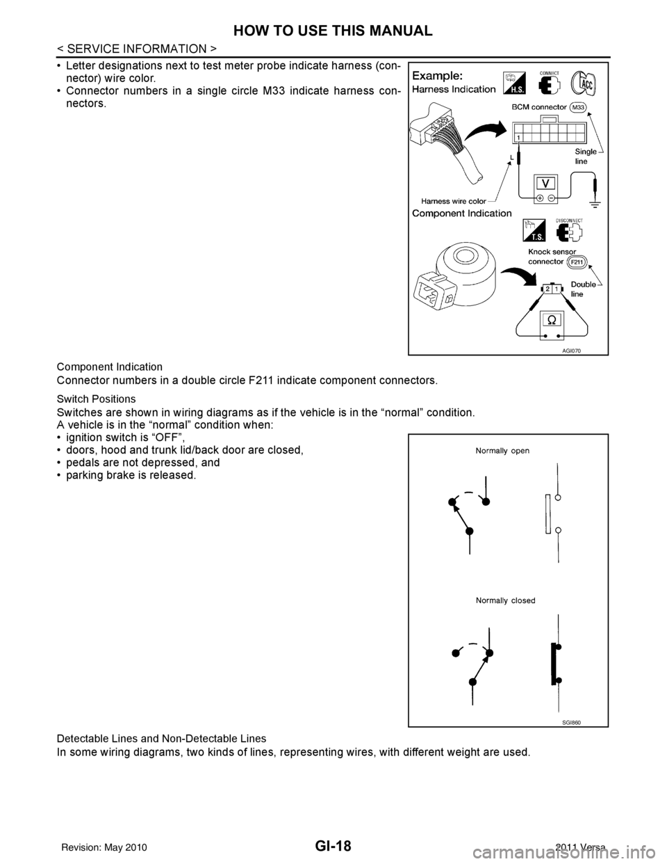
• Letter designations next to test meter probe indicate harness (con-nector) wire color.
• Connector numbers in a single circle M33 indicate harness con-
nectors.
Component Indication
Connector numbers in a double circle F211 indicate component connectors.
Switch Positions
Switches are shown in wiring diagrams as if the vehicle is in the “normal” condition.
A vehicle is in the “normal” condition when:
• ignition switch is “OFF”,
• doors, hood and trunk lid/back door are closed,
• pedals are not depressed, and
• parking brake is released.
Detectable Lines and Non-Detectable Lines
In some wiring diagrams, two kinds of lines, r epresenting wires, with different weight are used.
AGI070
SGI860
Revision: May 2010 2011 Versa
Page 2730 of 3787

GI-26
< SERVICE INFORMATION >
SERVICE INFORMATION FOR ELECTRICAL INCIDENT
• Cold or hot start up
Get a thorough description of the incident from the customer. It is important for simulating the conditions of the
problem.
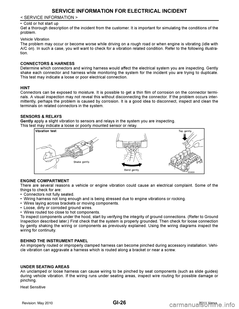
Vehicle Vibration
The problem may occur or become worse while driving on a rough road or when engine is vibrating (idle with
A/C on). In such a case, you will want to check for a vibration related condition. Refer to the following illustra-
tion.
CONNECTORS & HARNESS
Determine which connectors and wiring harness would affect the electrical system you are inspecting. Gently
shake each connector and harness while monitoring the sy stem for the incident you are trying to duplicate.
This test may indicate a loose or poor electrical connection.
HINT
Connectors can be exposed to moisture. It is possible to get a thin film of corrosion on the connector termi-
nals. A visual inspection may not reveal this without disconnecting the connector. If the problem occurs inter-
mittently, perhaps the problem is caused by corrosion. It is a good idea to disconnect, inspect and clean the
terminals on related connectors in the system.
SENSORS & RELAYS
Gently apply a slight vibration to sensors and relays in the system you are inspecting.
This test may indicate a loose or poorly mounted sensor or relay.
ENGINE COMPARTMENT
There are several reasons a vehicle or engine vibration could cause an e\
lectrical complaint. Some of the
things to check for are:
• Connectors not fully seated.
• Wiring harness not long enough and is being stressed due to engine vibrations or rocking.
• Wires laying across brackets or moving components.
• Loose, dirty or corroded ground wires.
• Wires routed too close to hot components.
To inspect components under the hood, start by verifyi ng the integrity of ground connections. (Refer to Ground
Inspection described later.) First check that the system is properly grounded. Then check for loose connection
by gently shaking the wiring or components as previous ly explained. Using the wiring diagrams inspect the
wiring for continuity.
BEHIND THE INSTRUMENT PANEL
An improperly routed or improperly clamped harness can become pinched during accessory installation. Vehi-
cle vibration can aggravate a harness which is routed along a bracket or near a screw.
UNDER SEATING AREAS
An unclamped or loose harness can cause wiring to be pinched by seat components (such as slide guides)
during vehicle vibration. If the wiring runs under s eating areas, inspect wire routing for possible damage or
pinching.
Heat Sensitive
SGI839
Revision: May 2010 2011 Versa
Page 2763 of 3787

SQUEAK AND RATTLE TROUBLE DIAGNOSESGW-9
< SERVICE INFORMATION >
C
DE
F
G H
J
K L
M A
B
GW
N
O P
Most of these incidents can be repaired by adjusting, se curing or insulating the item(s) or component(s) caus-
ing the noise.
SUNROOF/HEADLINING
Noises in the sunroof/headlining area can often be traced to one of the following:
1. Sunroof lid, rail, linkage or seals making a rattle or light knocking noise
2. Sun visor shaft shaking in the holder
3. Front or rear windshield touching headliner and squeaking
Again, pressing on the components to stop the noise while duplicating the conditions can isolate most of these
incidents. Repairs usually consist of insulating with felt cloth tape.
OVERHEAD CONSOLE (FRONT AND REAR)
Overhead console noises are often caused by the cons ole panel clips not being engaged correctly. Most of
these incidents are repaired by pushing up on the c onsole at the clip locations until the clips engage.
In addition look for:
1. Loose harness or harness connectors.
2. Front console map/reading lamp lense loose.
3. Loose screws at console attachment points.
SEATS
When isolating seat noise it's important to note the position the seat is in and the load placed on the seat when
the noise is present. These conditions should be duplicated when verifying and isolating the cause of the
noise.
Cause of seat noise include:
1. Headrest rods and holder
2. A squeak between the seat pad cushion and frame
3. The rear seatback lock and bracket
These noises can be isolated by moving or pressing on the suspected components while duplicating the con-
ditions under which the noise occurs. Most of thes e incidents can be repaired by repositioning the component
or applying urethane tape to the contact area.
UNDERHOOD
Some interior noise may be caused by components under the hood or on the engine wall. The noise is then
transmitted into the passenger compartment.
Causes of transmitted underhood noise include:
1. Any component mounted to the engine wall
2. Components that pass through the engine wall
3. Engine wall mounts and connectors
4. Loose radiator mounting pins
5. Hood bumpers out of adjustment
6. Hood striker out of adjustment
These noises can be difficult to isolate since they cannot be reached from the interior of the vehicle. The best
method is to secure, move or insulate one component at a time and test drive the vehicle. Also, engine RPM
or load can be changed to isolate the noise. Repairs can usually be made by moving, adjusting, securing, or
insulating the component causing the noise.
Revision: May 2010 2011 Versa
Page 2829 of 3787

IP-8
< SYMPTOM DIAGNOSIS >
SQUEAK AND RATTLE TROUBLE DIAGNOSES
2. Trunk lid striker out of adjustment
3. The trunk lid torsion bars knocking together
4. A loose license plate or bracket
Most of these incidents can be repaired by adjusting, securing or insulating the item(s) or component(s) caus-
ing the noise.
SUNROOF/HEADLINING
Noises in the sunroof/headlining area c an often be traced to one of the following:
1. Sunroof lid, rail, linkage or seals making a rattle or light knocking noise
2. Sun visor shaft shaking in the holder
3. Front or rear windshield touching headliner and squeaking
Again, pressing on the components to stop the noise while duplicating the conditions can isolate most of these
incidents. Repairs usually consist of insulating with felt cloth tape.
OVERHEAD CONSOLE (FRONT AND REAR)
Overhead console noises are often caused by the c onsole panel clips not being engaged correctly. Most of
these incidents are repaired by pushing up on the c onsole at the clip locations until the clips engage.
In addition look for:
1. Loose harness or harness connectors.
2. Front console map/reading lamp lens loose.
3. Loose screws at console attachment points.
SEATS
When isolating seat noise it's important to note the pos ition the seat is in and the load placed on the seat when
the noise is present. These conditions should be duplicated when verifying and isolating the cause of the
noise.
Cause of seat noise include:
1. Headrest rods and holder
2. A squeak between the seat pad cushion and frame
3. The rear seatback lock and bracket
These noises can be isolated by moving or pressing on the suspected components while duplicating the con-
ditions under which the noise occurs. Most of thes e incidents can be repaired by repositioning the component
or applying urethane tape to the contact area.
UNDERHOOD
Some interior noise may be caused by components under the hood or on the engine wall. The noise is then
transmitted into the passenger compartment.
Causes of transmitted underhood noise include:
1. Any component mounted to the engine wall
2. Components that pass through the engine wall
3. Engine wall mounts and connectors
4. Loose radiator mounting pins
5. Hood bumpers out of adjustment
6. Hood striker out of adjustment
These noises can be difficult to isolate since they cannot be reached from the interior of the vehicle. The best
method is to secure, move or insulate one component at a time and test drive the \
vehicle. Also, engine RPM
or load can be changed to isolate the noise. Repairs can usually be made by moving, adjusting, securing, or
insulating the component causing the noise.
Revision: May 2010 2011 Versa
Page 2837 of 3787

IP-16
< ON-VEHICLE REPAIR >
INSTRUMENT PANEL ASSEMBLY
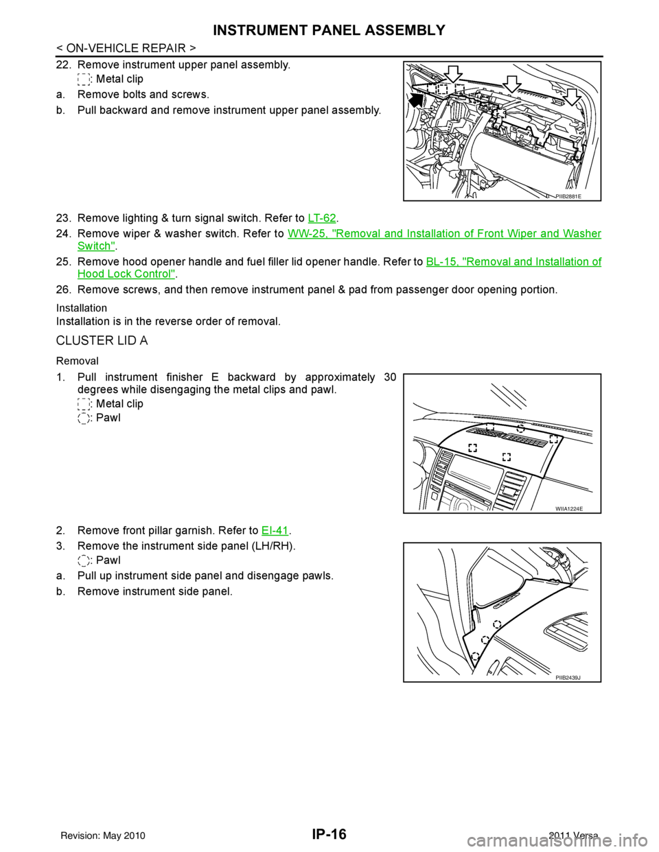
22. Remove instrument upper panel assembly.: Metal clip
a. Remove bolts and screws.
b. Pull backward and remove instrument upper panel assembly.
23. Remove lighting & turn signal switch. Refer to LT- 6 2
.
24. Remove wiper & washer switch. Refer to WW-25, "
Removal and Installation of Front Wiper and Washer
Switch".
25. Remove hood opener handle and fuel filler lid opener handle. Refer to BL-15, "
Removal and Installation of
Hood Lock Control".
26. Remove screws, and then remove instrument panel & pad from passenger door opening portion.
Installation
Installation is in the reverse order of removal.
CLUSTER LID A
Removal
1. Pull instrument finisher E backward by approximately 30
degrees while disengaging the metal clips and pawl.
: Metal clip
: Pawl
2. Remove front pillar garnish. Refer to EI-41
.
3. Remove the instrument side panel (LH/RH). : Pawl
a. Pull up instrument side panel and disengage pawls.
b. Remove instrument side panel.
PIIB2881E
WIIA1224E
PIIB2439J
Revision: May 2010 2011 Versa