Page 156 of 3787
P0750 SHIFT SOLENOID AAT-139
< SERVICE INFORMATION >
DE
F
G H
I
J
K L
M A
B
AT
N
O P
Wiring Diagram - AT - SSV/AINFOID:0000000005928191
TCM TERMINALS AND REFERENCE VALUES
Refer to AT-75, "TCM Terminal and Reference Value".
BCWA0655E
Revision: May 2010 2011 Versa
Page 161 of 3787
AT-144
< SERVICE INFORMATION >
P0755 SHIFT SOLENOID B
Wiring Diagram - AT - SSV/B
INFOID:0000000005928199
TCM TERMINALS AND REFERENCE VALUES
Refer to AT-75, "TCM Terminal and Reference Value".
BCWA0656E
Revision: May 2010 2011 Versa
Page 166 of 3787
P1760 OVERRUN CLUTCH SOLENOIDAT-149
< SERVICE INFORMATION >
DE
F
G H
I
J
K L
M A
B
AT
N
O P
Wiring Diagram - AT - OVRCSVINFOID:0000000005928207
TCM TERMINALS AND REFERENCE VALUES
Refer to AT-75, "TCM Terminal and Reference Value".
BCWA0657E
Revision: May 2010 2011 Versa
Page 171 of 3787
AT-154
< SERVICE INFORMATION >
VEHICLE SPEED SIGNAL
Wiring Diagram - AT - VSSMTR
INFOID:0000000005928215
TCM TERMINALS AND REFERENCE VALUES
Refer to AT-75, "TCM Terminal and Reference Value".
BCWA0658E
Revision: May 2010 2011 Versa
Page 174 of 3787
BATT/FLUID TEMP SENAT-157
< SERVICE INFORMATION >
DE
F
G H
I
J
K L
M A
B
AT
N
O P
Wiring Diagram - AT - BA/FTSINFOID:0000000005928222
TCM TERMINALS AND REFERENCE VALUES
Refer to AT-75, "TCM Terminal and Reference Value".
BCWA0659E
Revision: May 2010 2011 Versa
Page 176 of 3787

BATT/FLUID TEMP SENAT-159
< SERVICE INFORMATION >
DE
F
G H
I
J
K L
M A
B
AT
N
O P
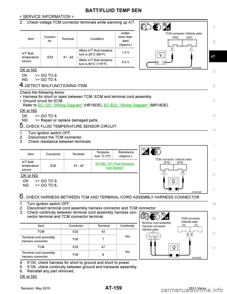
2. Check voltage TCM connector terminals while warming up A/T.
OK or NG
OK >> GO TO 9.
NG >> GO TO 4.
4.DETECT MALFUNCTIONING ITEM
Check the following items:
• Harness for short or open between TCM, ECM and terminal cord assembly
• Ground circuit for ECM Refer to EC-123, "
Wiring Diagram" (HR16DE), EC-633, "Wiring Diagram" (MR18DE).
OK or NG
OK >> GO TO 5.
NG >> Repair or replace damaged parts.
5. CHECK FLUID TEMPERATURE SENSOR CIRCUIT
1. Turn ignition switch OFF.
2. Disconnect the TCM connector.
3. Check resistance between terminals.
OK or NG
OK >> GO TO 9.
NG >> GO TO 6.
6. CHECK HARNESS BETWEEN TCM AND TERMINAL CORD ASSEMBLY HARNESS CONNECTOR
1. Turn ignition switch OFF.
2. Disconnect terminal cord assemb ly harness connector and TCM connector.
3. Check continuity between terminal cord assembly harness con- nector terminal and TCM connector terminal.
4. If OK, check harness for short to ground and short to power.
5. If OK, check continuity between ground and transaxle assembly.
6. Reinstall any part removed.
OK or NG
Item Connec-
tor Terminal
Condition Judge-
ment stan-
dard
(Approx.)
A/T fluid
temperature
sensor E32 47 - 42 When A/T fluid tempera-
ture is 20
°C (68 °F). 1.5 V
When A/T fluid tempera-
ture is 80 °C (176 °F). 0.5 V
SCIA2658E
Item Connector Terminal Te m p e r a -
ture ° C (°F) Resistance
(Approx.)
A/T fluid
temperature
sensor E32
47 - 42AT- 3 8 0 , "
A/T Fluid Tempera-
ture Sensor"
SCIA2338E
Item
Connector Terminal Continuity
TCM E3242
Ye s
Terminal cord assembly
harness connector F30
7
TCM E3247
Ye s
Terminal cord assembly
harness connector F30
6
SCIA2660E
Revision: May 2010 2011 Versa
Page 180 of 3787
INPUT SPEED SENSOR AAT-163
< SERVICE INFORMATION >
DE
F
G H
I
J
K L
M A
B
AT
N
O P
Wiring Diagram - AT - PT/SENINFOID:0000000005928230
TCM TERMINALS AND REFERENCE VALUES
Refer to AT-75, "TCM Terminal and Reference Value".
ABDWA0214GB
Revision: May 2010 2011 Versa
Page 181 of 3787

AT-164
< SERVICE INFORMATION >
INPUT SPEED SENSOR A
Diagnosis Procedure
INFOID:0000000005928231
1.CHECK INPUT SIGNAL
With CONSULT-III
1. Start engine.
2. Select “TCM INPUT SIGNALS” in “DATA MONITOR” mode for “TRANSMISSION” with CONSULT-III.
3. Read out the value of “INPUT SPEED” while driving. Check the value changes according to driving speed.
OK or NG
OK >> GO TO 8.
NG >> GO TO 2.
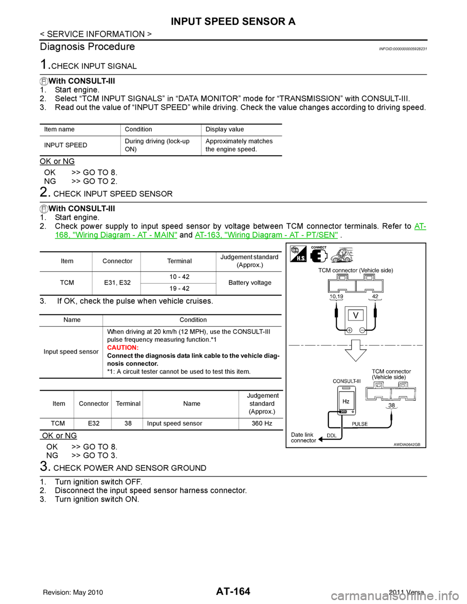
2. CHECK INPUT SPEED SENSOR
With CONSULT-III
1. Start engine.
2. Check power supply to input speed sensor by voltage between TCM connector terminals. Refer to AT-
168, "Wiring Diagram - AT - MAIN" and AT-163, "Wiring Diagram - AT - PT/SEN" .
3. If OK, check the pulse when vehicle cruises.
OK or NG
OK >> GO TO 8.
NG >> GO TO 3.
3. CHECK POWER AND SENSOR GROUND
1. Turn ignition switch OFF.
2. Disconnect the input speed sensor harness connector.
3. Turn ignition switch ON.
Item name ConditionDisplay value
INPUT SPEED During driving (lock-up
ON)Approximately matches
the engine speed.
Item Connector
TerminalJudgement standard
(Approx.)
TCM E31, E32 10 - 42
Battery voltage
19 - 42
Name Condition
Input speed sensor When driving at 20 km/h (12 MPH), use the CONSULT-III
pulse frequency measuring function.*1
CAUTION:
Connect the diagnosis data link
cable to the vehicle diag-
nosis connector.
*1: A circuit tester cannot be used to test this item.
Item Connector Terminal Name Judgement
standard
(Approx.)
TCM E32 38 Input speed sensor 360 Hz
AWDIA0642GB
Revision: May 2010 2011 Versa