2011 NISSAN TIIDA remote control
[x] Cancel search: remote controlPage 729 of 3787

VEHICLE SECURITY (THEFT WARNING) SYSTEMBL-219
< SERVICE INFORMATION >
C
DE
F
G H
J
K L
M A
B
BL
N
O P
• to combination meter terminal 27 (security indicator lamp)
• through 40A fusible link (letter g, located in the fuse and fusible link box)
• to BCM terminal 70
• through 10A fuse [No. 8, located in the fuse block (J/B)]
• to BCM terminal 57
• through 10A fuse (No. 28, located in the fuse and fusible link box)
• to horn relay terminal 2
• through 15A fuse (No. 52, located in the IPDM E/R)
• to IPDM E/R internal CPU.
• through 20A fuse (No. 53, located in the IPDM E/R)
• to IPDM E/R internal CPU.
With the ignition switch in the ACC or ON position, power is supplied• through 10A fuse [No. 20, located in the fuse block (J/B)]
• to BCM terminal 11.
With the ignition switch in the ON or START position, power is supplied• through 10A fuse [No. 6, located in the fuse block (J/B)]
• to BCM terminal 38.
Ground is supplied• to BCM terminal 67
• through body grounds M57 and M61.
INITIAL CONDITION TO ACTIVATE THE SYSTEM
The operation of the vehicle security system is controlled by the doors and trunk (sedan).
To activate the vehicle security system, BCM must receive signals indicating the ignition switch is OFF, doors
and trunk (sedan) are closed and locked.
When a door or trunk (sedan) is open, BCM terminal 12, 13, 42, 43, 47 or 48 receives a ground signal from
each door or trunk switch. In addition to BCM, when back door is open, the Intelligent Key unit terminal 23
receives a ground signal from back door or trunk (sedan) through BCM terminal 30.
When front door LH is unlocked, BCM terminal 46 receives a signal from terminal 6 of main power window and
door lock/unlock switch.
When front door RH is unlocked, BCM terminal 46 receives a signal from terminal 2 of power window and door
lock/unlock switch RH.
VEHICLE SECURITY SYSTEM ALARM OPERATION
The vehicle security system is triggered by
• Opening a door without using the key, keyfob or Intelligent Key.
• Opening trunk without using the key, keyfob or Intelligent Key (sedan).
The vehicle security system will be triggered once the system is in armed phase,
• when BCM receives a ground signal at terminals 12, 13, 47, 48 (front or rear door switch), terminal 42 (sedan, trunk switch) or terminal 43 (hatchback, back door switch).
When the vehicle security system is triggered, ground is supplied intermittently
• from IPDM E/R terminal 45
• to horn relay terminal 1.
The headlamps flash and the hor n sounds intermittently.
The alarm automatically turns off after 50 seconds, but will reactivate if the vehicle is tampered with again.
VEHICLE SECURITY SYSTEM DEACTIVATION
To deactivate the vehicle security system, a door or trunk (sedan) must be unlocked with the key, keyfob or
Intelligent Key.
When the key is used to unlock the driver door, BCM terminal 7 receives signal
• from terminal 3 of the front door lock assembly LH (key cylinder switch).
When the key is used to open the trunk (sedan), BCM terminal 41 receives signal
• from terminal 1 of the trunk key cylinder switch.
When the BCM receives an unlock signal from keyfob, Intelligent Key, front door key cylinder switch LH or
trunk key cylinder switch (sedan), the vehicle security system is deactivated (Disarmed phase).
PANIC ALARM OPERATION
Intelligent Key and remote keyless entry system may or may not operate vehicle security system (horn and
headlamps) as required.
When the vehicle security system is triggered, ground is supplied intermittently
Revision: May 2010 2011 Versa
Page 737 of 3787
VEHICLE SECURITY (THEFT WARNING) SYSTEMBL-227
< SERVICE INFORMATION >
C
DE
F
G H
J
K L
M A
B
BL
N
O P
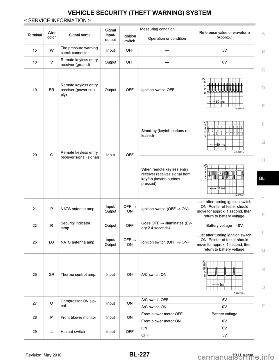
15 W Tire pressure warning
check connector
Input OFF
—5V
18 V Remote keyless entry
receiver (ground) Output OFF
—0V
19 BR Remote keyless entry
receiver (power sup-
ply) Output OFF Ignition switch OFF
20 G Remote keyless entry
receiver signal (signal)
Input OFFStand-by (keyfob buttons re-
leased)
When remote keyless entry
receiver receives signal from
keyfob (keyfob buttons
pressed)
21 P NATS antenna amp. Input/
Output OFF
→
ON Ignition switch (OFF → ON) Just after turning ignition switch
ON: Pointer of tester should
move for approx. 1 second, then
return to battery voltage.
23 R Security indicator
lamp Output OFF
Goes OFF
→ illuminates (Ev-
ery 2.4 seconds) Battery voltage
→ 0V
25 LG NATS antenna amp. Input/
Output OFF
→
ON Ignition switch (OFF → ON) Just after turning ignition switch
ON: Pointer of tester should
move for approx. 1 second, then return to battery voltage.
26 GR Thermo control amp. Input ON A/C switch ON
27 O Compressor ON sig-
nal Input ONA/C switch OFF
5V
A/C switch ON 0V
28 P Front blower monitor Input ON Front blower motor OFF
Battery voltage
Front blower motor ON 0V
29 L Hazard switch Input OFFON
0V
OFF 5V
Te r m i n a l
Wire
color Signal name Signal
input/
output Measuring condition
Reference value or waveform
(Approx.)
Ignition
switch Operation or condition
LIIA1893E
LIIA1894E
LIIA1895E
ZJIA0719J
Revision: May 2010
2011 Versa
Page 761 of 3787
NATS (NISSAN ANTI-THEFT SYSTEM)BL-251
< SERVICE INFORMATION >
C
DE
F
G H
J
K L
M A
B
BL
N
O P
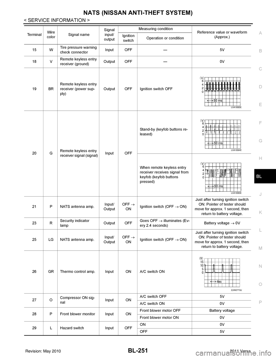
15 W Tire pressure warning
check connector
Input OFF
—5V
18 V Remote keyless entry
receiver (ground) Output OFF
—0V
19 BR Remote keyless entry
receiver (power sup-
ply) Output OFF Ignition switch OFF
20 G Remote keyless entry
receiver signal (signal)
Input OFFStand-by (keyfob buttons re-
leased)
When remote keyless entry
receiver receives signal from
keyfob (keyfob buttons
pressed)
21 P NATS antenna amp. Input/
Output OFF
→
ON Ignition switch (OFF → ON) Just after turning ignition switch
ON: Pointer of tester should
move for approx. 1 second, then
return to battery voltage.
23 R Security indicator
lamp Output OFF
Goes OFF
→ illuminates (Ev-
ery 2.4 seconds) Battery voltage
→ 0V
25 LG NATS antenna amp. Input/
Output OFF
→
ON Ignition switch (OFF → ON) Just after turning ignition switch
ON: Pointer of tester should
move for approx. 1 second, then return to battery voltage.
26 GR Thermo control amp. Input ON A/C switch ON
27 O Compressor ON sig-
nal Input ONA/C switch OFF
5V
A/C switch ON 0V
28 P Front blower monitor Input ON Front blower motor OFF
Battery voltage
Front blower motor ON 0V
29 L Hazard switch Input OFFON
0V
OFF 5V
Te r m i n a l
Wire
color Signal name Signal
input/
output Measuring condition
Reference value or waveform
(Approx.)
Ignition
switch Operation or condition
LIIA1893E
LIIA1894E
LIIA1895E
ZJIA0719J
Revision: May 2010
2011 Versa
Page 3083 of 3787

TURN SIGNAL AND HAZARD WARNING LAMPSLT-51
< SERVICE INFORMATION >
C
DE
F
G H
I
J
L
M A
B
LT
N
O P
• through grounds B7 and B19.
The BCM also sends a request, via the CAN communication lines, to the combination meter to flash the left
turn signal indicator. The unified meter control unit in the combination meter supplies ground to the \
left turn
signal indicator lamp and activates the audible turn signal indicator.
With power, ground and input supplied, the BCM controls the flashing of the turn signal lamps.
RH Turn Signal Lamp
When turn signal switch is moved to the right turn position, the BCM receives an input signal requesting right
turn signals to flash. The BCM then supplies power
• through BCM terminal 61
• to front combination lamp RH terminal 4 and
• to rear combination lamp RH terminal 6.
Ground is supplied
• to front combination lamp RH terminal 5
• through grounds E15 and E24,
• to rear combination lamp RH terminal 1
• through grounds B117, B132 (all models) and D402 (with hatchback).
The BCM also sends a request, via the CAN communication lines, to the combination meter to flash the right
turn signal indicator. The unified meter control unit in the combination meter supplies ground to the right turn
signal indicator lamp and activates the audible turn signal indicator.
With power, ground and input supplied, the BCM controls the flashing of the turn signal lamps.
HAZARD LAMP OPERATION
Power is supplied at all times
• through 40A fusible link (letter g , located in fuse, fusible link and relay box)
• to BCM terminal 70,
• through 10A fuse [No. 8, located in fuse block (J/B)]
• to BCM terminal 57,
• through 10A fuse [No. 13, located in fuse block (J/B)]
• to combination meter terminal 27.
Ground is supplied
• to hazard switch terminal 1,
• to BCM terminal 67, and
• to combination meter terminals 21, 22 and 23
• through grounds M57 and M61.
When hazard switch is depressed, ground is supplied
• through hazard switch terminal 2
• to BCM terminal 29.
BCM then supplies power
• to front combination lamp LH terminal 4 and
• to rear combination lamp LH terminal 6
• through BCM terminal 60,
• to front combination lamp RH terminal 4 and
• to rear combination lamp RH terminal 6
• through BCM terminal 61.
Ground is supplied
• to front combination lamp LH and RH terminal 5
• through grounds E15 and E24,
• to rear combination lamp LH terminal 1
• through grounds B7 and B19,
• to rear combination lamp RH terminal 1
• through grounds B117, B132 and D402 (hatchback).
The BCM also supplies input to combination meter ac ross the CAN communication lines. This input is pro-
cessed by unified meter control unit in combination mete r, which in turn supplies ground to the left and right
turn signal indicator lamps.
With power and input supplied, BCM controls flashing of hazard warning lamps.
REMOTE KEYLESS ENTRY SYSTEM OPERATION
Power is supplied at all times
• through 40A fusible link (letter g , located in fuse, fusible link and relay box)
• to BCM terminal 70,
• through 10A fuse [No. 13, located in fuse block (J/B)]
Revision: May 2010 2011 Versa
Page 3084 of 3787

LT-52
< SERVICE INFORMATION >
TURN SIGNAL AND HAZARD WARNING LAMPS
• to combination meter terminal 27.
Ground is supplied
• to BCM terminal 67 and
• to combination meter terminals 21, 22 and 23
• through grounds M57 and M61.
When the remote keyless entry system is triggered by input from the keyfob, the BCM supplies power
• through BCM terminal 60
• to front combination lamp LH terminal 4 and
• to rear combination lamp LH terminal 6,
• through BCM terminal 61
• to front turn signal lamp RH terminal 4 and
• to rear combination lamp RH terminal 6.
Ground is supplied
• to front combination lamp LH and RH terminals 5
• through grounds E15 and E24,
• to rear combination lamp LH terminal 1
• through grounds B7 and B19,
• to rear combination lamp RH terminal 1
• through grounds B117, B132 (all m odels) and D402 (with hatchback).
The BCM also supplies input to combination meter via the CAN communication lines. This input is processed
by the unified meter control unit in combination meter, which in turn supplies ground to the left and right turn
signal indicator lamps.
With power and ground supplied, BCM controls flashing of hazard warning lamps when keyfob is used to acti-
vate remote keyless entry system.
COMBINATION SWITCH READING FUNCTION
Refer to BCS-4, "System Description" .
CAN Communication System DescriptionINFOID:0000000005929082
Refer to LAN-7, "System Description" .
Revision: May 2010 2011 Versa
Page 3136 of 3787

LT-104
< SERVICE INFORMATION >
INTERIOR ROOM LAMP
1 : With remote keyless entry system
2: With Intelligent Key system
WORK SUPPORT
Display Item List
Interior Room Lamp Control Does Not Operate (With Map Lamp)INFOID:0000000005929146
1.CHECK EACH SWITCH
Select "BCM" on CONSULT-III. With "INT LAMP" data monitor, make sure switches listed in display item list
turn ON-OFF linked with switch operation. Refer to BCS-17, "
CONSULT-III Function (BCM)" for switches and
their functions.
OK or NG
OK >> GO TO 2.
NG >> Inspect malfunctioning switch system.
2.ACTIVE TEST
1. Select “BCM” on CONSULT-III. Select “INT LAMP" active test.
2. When room lamp switch is in DOOR position, make sure room lamp operates.
OK or NG
OK >> Replace BCM. Refer to BCS-19, "Removal and Installation of BCM" .
NG >> GO TO 3.
3.CHECK ROOM LAMP INPUT VOLTAGE
Blower fan switch sig-
nal
Air conditioner switch
signal AIR CONDITION-
ER
××
Combination switch COMB SW ×
NVIS (NATS) IMMU ××
Interior lamp battery
saver BATTERY SAV-
ER
××
×
Back door/Trunk TRUNK/BACK
DOOR ××
Theft alarm THEFT ALM×× ×
Retained accessory
power control RETAINED PWR
×× ×
Oil pressure swit ch SIGNAL BUFFER ××
Panic alarm PANIC ALARM ×
Remote keyless entry
system
1MULTI REMOTE
ENTRY ××
×
System and item
CONSULT-III dis-
play Diagnostic test mode (Inspection by part)
WORK
SUPPORT SELF
−
DIAG RE-
SULTS CAN DIAG
SUPPORT
MNTR DATA
MONITOR ECU
PA R T
NUMBER AC-
TIVE
TEST CON-
FIGU-
RATION
Item Description
RESET SETTING VALUE Return a value set with WORK SUPPORT of each system to a default value in factory shipment.
Room lamp should operate.
Revision: May 2010 2011 Versa
Page 3141 of 3787

ILLUMINATIONLT-109
< SERVICE INFORMATION >
C
DE
F
G H
I
J
L
M A
B
LT
N
O P
ILLUMINATION
System DescriptionINFOID:0000000005929150
The control of the illumination lamps operation is dependent upon the position of the lighting switch. When the
lighting switch is placed in the 1ST or 2ND position, the BCM (body control module) receives input signal
requesting the illumination lamps to illuminate. This input signal is communicated to IPDM E/R (intelligent
power distribution module engine room) across CAN communication lines. CPU (central processing unit)
located in the IPDM E/R controls the tail lamp relay coil . This relay, when energized, directs power to the illu-
mination lamps, which then illuminate.
Power is supplied at all times
• to ignition relay, located in IPDM E/R,
• to tail lamp relay, located in IPDM E/R,
• through 15A fuse (No. 52, located in IPDM E/R) and
• through 20A fuse (No. 53, located in IPDM E/R)
• to CPU located in IPDM E/R,
• through 40A fusible link (letter g, located in fuse and fusible link box)
• to BCM terminal 70, and
• through 10A fuse [No. 8, located in fuse block (J/B)]
• to BCM terminal 57.
With the ignition switch in the ON or START position, power is supplied
• to ignition relay, located in IPDM E/R, and
• through 10A fuse [No. 6, located in fuse block (J/B)]
• to BCM terminal 38.
With the ignition switch in the ACC or ON position, power is supplied
• through 10A fuse [No. 20, located in fuse block (J/B)]
• to BCM terminal 11.
Ground is supplied
• to BCM terminal 67
• through grounds M57 and M61
• to IPDM E/R terminals 39 and 59, and
• through grounds E15 and E24.
ILLUMINATION OPERATION BY LIGHTING SWITCH
With the lighting switch in the 1ST or 2ND positi on, BCM receives input signal requesting the illumination
lamps to illuminate. This input signal is communicat ed to IPDM E/R across CAN communication lines. CPU
located in the IPDM E/R controls the tail lamp relay coil, which, when energized, directs power
• through 10A fuse (No. 37, located in IPDM E/R)
• through IPDM E/R terminal 29
• to illumination control switch terminal 1
• to VDC OFF switch terminal 3 (with VDC)
• to audio unit terminal 9
• to front air control terminal 5
• to A/T shift selector terminal 3 (with 4-speed A/T)
• to CVT shift selector terminal 3 (with CVT)
• to hazard switch terminal 3
• to combination meter terminal 12
• to door mirror remote control switch terminal 16
• to combination switch (spiral cable) terminal 26 (with steering wheel audio control switches)
• to steering wheel audio control switches through combinat ion switch (spiral cable) terminal 18 (with steering
wheel audio control switches).
Ground is supplied
• to VDC OFF switch terminal 4 (with VDC)
• to illumination control switch terminal 3, and
• through grounds M57 and M61.
The illumination control switch controls illuminat ion intensity by varying the ground to the following
• through illumination control switch terminal 2
• to audio unit terminal 8
• to front air control terminal 6
• to A/T shift selector terminal 4 (with 4-speed A/T)
• to CVT shift selector terminal 3 (with CVT)
Revision: May 2010 2011 Versa
Page 3142 of 3787

LT-110
< SERVICE INFORMATION >
ILLUMINATION
• to hazard switch terminal 4
• to combination meter terminal 13
• to door mirror remote control switch terminal 15
• to combination switch (spiral cable) terminal 27 (with steering wheel audio control switches)
• to steering wheel audio control switches through combination switch (spiral cable) terminal 21 (with steeringwheel audio control switches).
With power and ground supplied, illumination lamps illuminate.
EXTERIOR LAMP BATTERY SAVER CONTROL
Refer to LT-74, "System Description".
CAN Communication System DescriptionINFOID:0000000005929151
Refer to LAN-7, "System Description" .
Revision: May 2010 2011 Versa