2011 NISSAN TIIDA fuel system
[x] Cancel search: fuel systemPage 2673 of 3787
FL-6
< SERVICE INFORMATION >
FUEL LEVEL SENSOR UNIT, FUEL FILTER AND FUEL PUMP ASSEMBLY
FUEL LEVEL SENSOR UNIT, FUEL FILTER AND FUEL PUMP ASSEMBLY
ComponentINFOID:0000000005931057
Removal and InstallationINFOID:0000000005931058
REMOVAL
WARNING:
Be sure to read “General Precautions” be fore working on the fuel system. Refer to FL-5, "
General Pre-
caution".
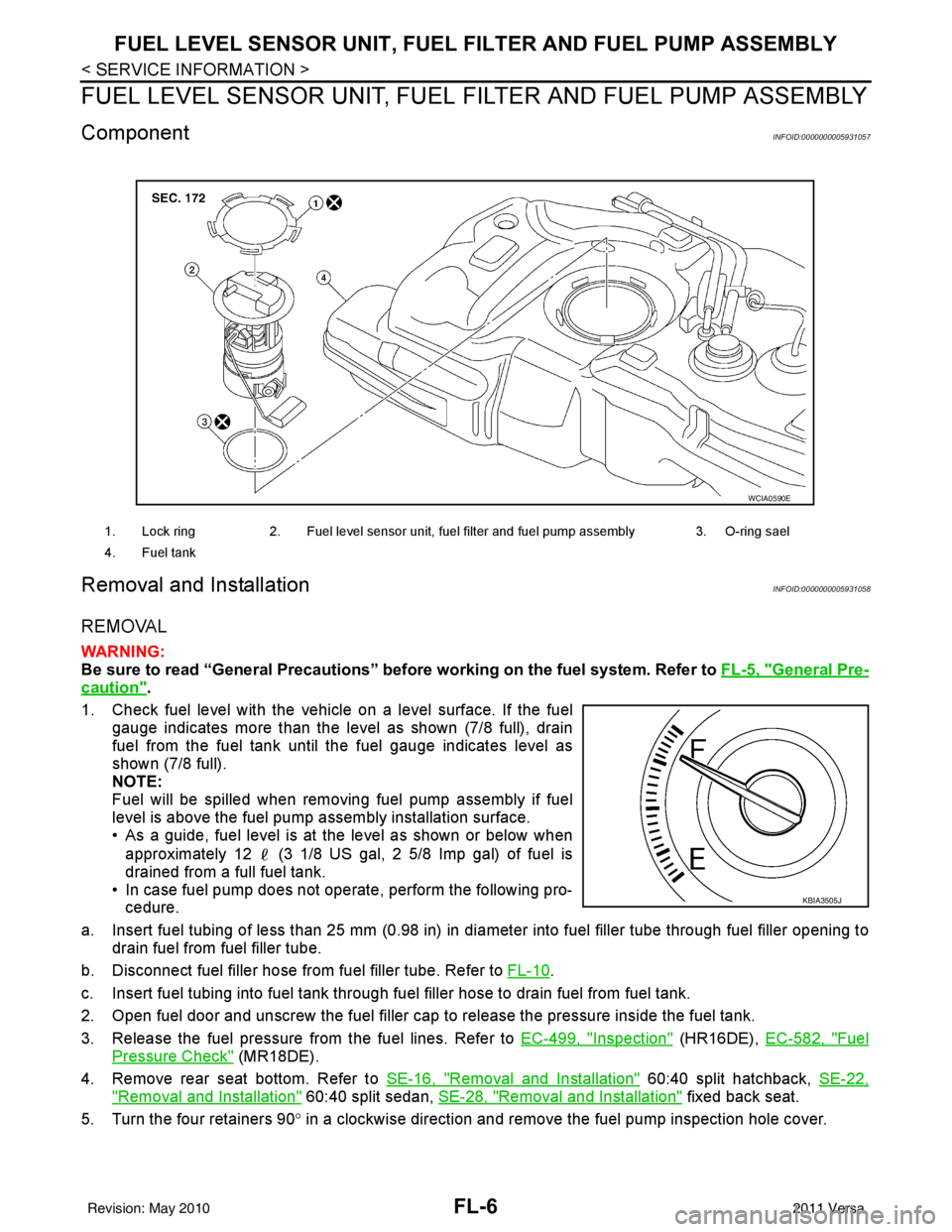
1. Check fuel level with the vehicle on a level surface. If the fuel gauge indicates more than the level as shown (7/8 full), drain
fuel from the fuel tank until the fuel gauge indicates level as
shown (7/8 full).
NOTE:
Fuel will be spilled when removing fuel pump assembly if fuel
level is above the fuel pump assembly installation surface.
• As a guide, fuel level is at the level as shown or below when
approximately 12 (3 1/8 US gal, 2 5/8 Imp gal) of fuel is
drained from a full fuel tank.
• In case fuel pump does not operate, perform the following pro- cedure.
a. Insert fuel tubing of less than 25 mm (0.98 in) in di ameter into fuel filler tube through fuel filler opening to
drain fuel from fuel filler tube.
b. Disconnect fuel filler hose from fuel filler tube. Refer to FL-10
.
c. Insert fuel tubing into fuel tank through f uel filler hose to drain fuel from fuel tank.
2. Open fuel door and unscrew the fuel filler cap to release the pressure inside the fuel tank.
3. Release the fuel pressure from the fuel lines. Refer to EC-499, "
Inspection" (HR16DE), EC-582, "Fuel
Pressure Check" (MR18DE).
4. Remove rear seat bottom. Refer to SE-16, "
Removal and Installation" 60:40 split hatchback, SE-22,
"Removal and Installation" 60:40 split sedan, SE-28, "Removal and Installation" fixed back seat.
5. Turn the four retainers 90 ° in a clockwise direction and remove the fuel pump inspection hole cover.
1. Lock ring 2. Fuel level sensor unit, fuel filter and fuel pump assembly 3. O-ring sael
4. Fuel tank
WCIA0590E
KBIA3505J
Revision: May 2010 2011 Versa
Page 2676 of 3787

FUEL LEVEL SENSOR UNIT, FUEL FILTER AND FUEL PUMP ASSEMBLYFL-9
< SERVICE INFORMATION >
C
DE
F
G H
I
J
K L
M A
FL
NP
O
Use the following procedure to check for fuel leaks.
1. Turn ignition switch “ON” (without starting the engi
ne), to check the connections for fuel leaks with the
electric fuel pump applying pressure to the fuel piping.
2. Start the engine and let it idle to check that ther e are no fuel leaks at the fuel system connections.
Revision: May 2010 2011 Versa
Page 2677 of 3787
FL-10
< SERVICE INFORMATION >
FUEL TANK
FUEL TANK
ComponentINFOID:0000000005931059
Removal and InstallationINFOID:0000000005931060
REMOVAL
WARNING:
Be sure to read “General Precautions” when working on the fuel system. Refer to FL-5, "
General Pre-
caution".
1. Drain fuel from fuel tank if necessary. Refer to FL-6, "
Removal and Installation".
CAUTION:
• Because fuel tank becomes unstable when installing/removing, fuel should be drained if the
level exceeds specification FL-6, "
Removal and Installation".
• Situate vehicle on a flat and solid surface.
2. Open fuel door and unscrew the fuel filler cap to release the pressure inside the fuel tank.
3. Release the fuel pressure from the fuel lines. Refer to EC-499, "
Inspection" (HR16DE), EC-582, "Fuel
Pressure Check" (MR18DE).
4. Remove rear seat bottom. Refer to SE-16, "
Removal and Installation" 60:40 split hatchback, SE-22,
"Removal and Installation" 60:40 split sedan, SE-28, "Removal and Installation" fixed back seat.
5. Turn the three retainers 90 ° in a clockwise direction and remove the fuel pump inspection hole cover.
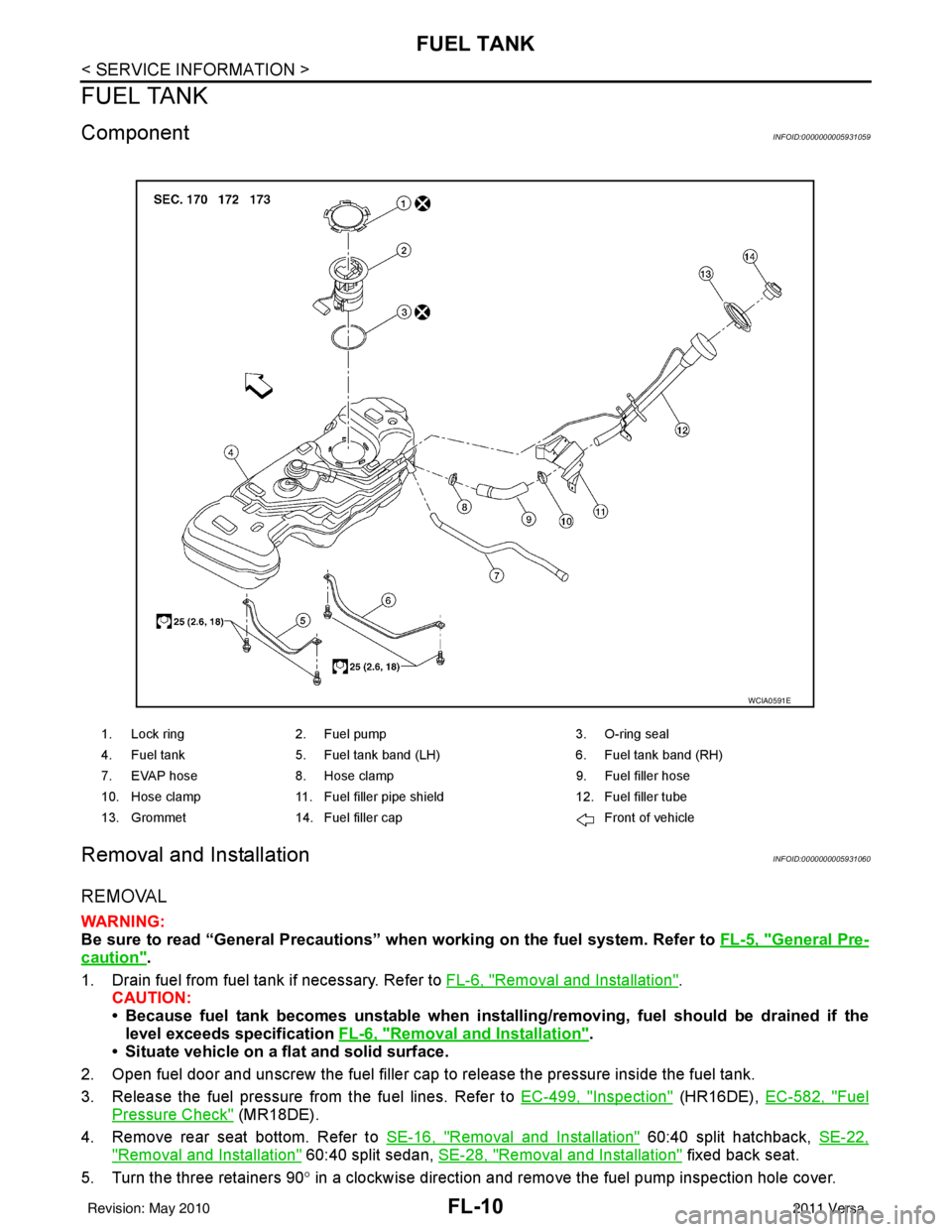
1. Lock ring 2. Fuel pump 3. O-ring seal
4. Fuel tank 5. Fuel tank band (LH) 6. Fuel tank band (RH)
7. EVAP hose 8. Hose clamp 9. Fuel filler hose
10. Hose clamp 11. Fuel filler pipe shield 12. Fuel filler tube
13. Grommet 14. Fuel filler cap Front of vehicle
WCIA0591E
Revision: May 2010 2011 Versa
Page 2681 of 3787

FL-14
< SERVICE INFORMATION >
FUEL TANK
2. Start the engine and let it idle to check that there are no fuel leaks at the fuel system connections.
Revision: May 2010 2011 Versa
Page 2682 of 3787
EVAPORATIVE EMISSION SYSTEMFL-15
< SERVICE INFORMATION >
C
DE
F
G H
I
J
K L
M A
FL
NP
O
EVAPORATIVE EMISSION SYSTEM
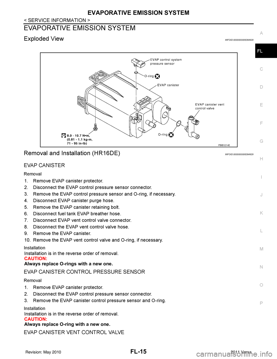
Exploded ViewINFOID:0000000006364928
Removal and Installation (HR16DE)INFOID:0000000006364929
EVAP CANISTER
Removal
1. Remove EVAP canister protector.
2. Disconnect the EVAP control pressure sensor connector.
3. Remove the EVAP control pressure sensor and O-ring, if necessary.
4. Disconnect EVAP canister purge hose.
5. Remove the EVAP canister retaining bolt.
6. Disconnect fuel tank
EVAP breather hose.
7. Disconnect EVAP vent control valve connector.
8. Disconnect the EVAP vent control valve hose.
9. Remove the EVAP canister.
10. Remove the EVAP vent control valve and O-ring, if necessary.
Installation
Installation is in the reverse order of removal.
CAUTION:
Always replace O-rings with a new one.
EVAP CANISTER CONTROL PRESSURE SENSOR
Removal
1. Remove EVAP canister protector.
2. Disconnect the EVAP control pressure sensor connector.
3. Remove the EVAP canister control pressure sensor and O-ring.
Installation
Installation is in the reverse order of removal.
CAUTION:
Always replace O-ring with a new one.
EVAP CANISTER VENT CONTROL VALVE
PBIB1214E
Revision: May 2010 2011 Versa
Page 2683 of 3787
FL-16
< SERVICE INFORMATION >
EVAPORATIVE EMISSION SYSTEM
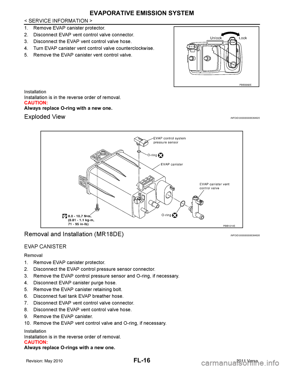
1. Remove EVAP canister protector.
2. Disconnect EVAP vent control valve connector.
3. Disconnect the EVAP vent control valve hose.
4. Turn EVAP canister vent control valve counterclockwise.
5. Remove the EVAP canister vent control valve.
Installation
Installation is in the reverse order of removal.
CAUTION:
Always replace O-ring with a new one.
Exploded ViewINFOID:0000000006364925
Removal and Installation (MR18DE)INFOID:0000000006364926
EVAP CANISTER
Removal
1. Remove EVAP canister protector.
2. Disconnect the EVAP control pressure sensor connector.
3. Remove the EVAP control pressure sensor and O-ring, if necessary.
4. Disconnect EVAP canister purge hose.
5. Remove the EVAP canister retaining bolt.
6. Disconnect fuel tank EVAP breather hose.
7. Disconnect EVAP vent control valve connector.
8. Disconnect the EVAP vent control valve hose.
9. Remove the EVAP canister.
10. Remove the EVAP vent control valve and O-ring, if necessary.
Installation
Installation is in the reverse order of removal.
CAUTION:
Always replace O-rings with a new one.
PBIB3082E
PBIB1214E
Revision: May 20102011 Versa
Page 2705 of 3787

GI-1
GENERAL INFORMATION
C
DE
F
G H
I
J
K L
M B
GI
SECTION GI
N
O P
CONTENTS
GENERAL INFORMATION
SERVICE INFORMATION .. ..........................2
PRECAUTIONS .............................................. .....2
Description .......................................................... ......2
Precaution for Supplemental Restraint System
(SRS) "AIR BAG" and "SEAT BELT PRE-TEN-
SIONER" ...................................................................
2
Precaution Necessary for Steering Wheel Rota-
tion After Battery Disconnect ............................... ......
2
General Precaution ...................................................3
Precaution for Three Way Catalyst ...........................4
Precaution for Fuel (Unleaded Regular Gasoline
Recommended) .........................................................
4
Precaution for Multiport Fuel Injection System or
Engine Control System .............................................
5
Precaution for Hoses .................................................5
Precaution for Engine Oils ........................................6
Precaution for Air Conditioning .................................6
HOW TO USE THIS MANUAL ............................7
Description .......................................................... ......7
Terms ........................................................................7
Units ..........................................................................7
Contents ....................................................................7
Relation between Illustrations and Descriptions .......8
Component ................................................................8
How to Follow Trouble Diagnosis ..............................9
How to Read Wiring Diagram ..................................13
Abbreviations ...................................................... ....20
SERVICE INFORMATION FOR ELECTRICAL
INCIDENT ...........................................................
22
How to Check Terminal ...........................................22
How to Perform Efficient Diagnosis for an Electri-
cal Incident .......................................................... ....
25
Control Units and Electrical Parts ............................32
CONSULT-III CHECKING SYSTEM .................35
Description ...............................................................35
Function and System Application ............................35
CONSULT-III Data Link Connector (DLC) Circuit ....36
LIFTING POINT .................................................38
Special Service Tool ................................................38
Garage Jack and Safety Stand and 2-Pole Lift .......38
Board-On Lift ...........................................................39
TOW TRUCK TOWING .....................................40
Tow Truck Towing ...................................................40
Vehicle Recovery (Freeing a Stuck Vehicle) ...........40
TIGHTENING TORQUE OF STANDARD
BOLTS ...............................................................
41
Tightening Torque Table .........................................41
RECOMMENDED CHEMICAL PRODUCTS
AND SEALANTS ...............................................
42
Recommended Chemical Product and Sealant .......42
IDENTIFICATION INFORMATION ....................43
Model Variation ........................................................43
Dimensions ..............................................................46
Wheels & Tires ........................................................46
TERMINOLOGY ................................................47
SAE J1930 Terminology List ...................................47
Revision: May 2010 2011 Versa
Page 2708 of 3787
GI-4
< SERVICE INFORMATION >
PRECAUTIONS
• Replace oil seals, gaskets, packings, O-rings, locking washers, cotter pins, self-locking nuts, etc. with new
ones.
• Replace inner and outer races of tapered roller bearings and needle bearings as a set.
• Arrange the disassembled parts in accordance with their assembled locations and sequence.
• Do not touch the terminals of electrical com ponents which use microcomputers (such as ECM).
Static electricity may damage internal electronic components.
• After disconnecting vacuum or air hoses, atta ch a tag to indicate the proper connection.
• Use only the fluids and lubricants specified in this manual.
• Use approved bonding agent, sealants or their equivalents when required.
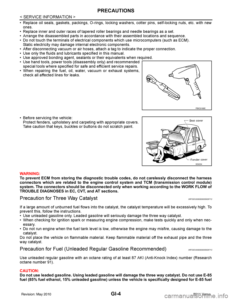
• Use hand tools, power tools (disassembly only) and recommended special tools where specified for safe and efficient service repairs.
• When repairing the fuel, oil, water, vacuum or exhaust systems, check all affected lines for leaks.
• Before servicing the vehicle: Protect fenders, upholstery and carpeting with appropriate covers.
Take caution that keys, buckles or buttons do not scratch paint.
WARNING:
To prevent ECM from storing the diagnostic tro uble codes, do not carelessly disconnect the harness
connectors which are related to the engine control system and TCM (transmission control module)
system. The connectors should be disconnected only when working according to the WORK FLOW of
TROUBLE DIAGNOSES in EC, CVT, and AT sections.
Precaution for Three Way CatalystINFOID:0000000005929712
If a large amount of unburned fuel flows into the catalyst , the catalyst temperature will be excessively high. To
prevent this, follow the instructions.
• Use unleaded gasoline only. Leaded gasoline will seriously damage the three way catalyst.
• When checking for ignition spark or measuring engine compression, make tests quickly and only when nec- essary.
• Do not run engine when the fuel tank level is low, otherwise the engine may misfire, causing damage to the
catalyst.
Do not place the vehicle on flammable material. Keep flammable material off the exhaust pipe and the three
way catalyst.
Precaution for Fuel (Unleade d Regular Gasoline Recommended)INFOID:0000000005929713
Use unleaded regular gasoline with an octane rating of at least 87 AKI (Anti-Knock Index) number (Research
octane number 91).
CAUTION:
Do not use leaded gasoline. Using leaded gasoline will damage the three way catalyst. Do not use E-85
fuel (85% fuel ethanol, 15% unleaded gasoline) unless the vehicle is specifically designed for E-85 fuel
PBIC0190E
SGI234
Revision: May 2010 2011 Versa