2011 NISSAN TIIDA hood open
[x] Cancel search: hood openPage 2110 of 3787
![NISSAN TIIDA 2011 Service Repair Manual EC-816
< SERVICE INFORMATION >[MR18DE]
DTC P0442 EVAP CONTROL SYSTEM
DTC Confirmation Procedure
INFOID:0000000006341982
NOTE:
If DTC Confirmation Procedure has been previously conducted, always turn i](/manual-img/5/57396/w960_57396-2109.png "NISSAN TIIDA 2011 Service Repair Manual EC-816
< SERVICE INFORMATION >[MR18DE]
DTC P0442 EVAP CONTROL SYSTEM
DTC Confirmation Procedure
INFOID:0000000006341982
NOTE:
If DTC Confirmation Procedure has been previously conducted, always turn i")
EC-816
< SERVICE INFORMATION >[MR18DE]
DTC P0442 EVAP CONTROL SYSTEM
DTC Confirmation Procedure
INFOID:0000000006341982
NOTE:
If DTC Confirmation Procedure has been previously conducted, always turn ignition switch OFF and wait at
least 10 seconds before conducting the next test.
TESTING CONDITION:
• Perform “DTC WORK SUPPORT” when the fuel level is between 1/4 and 3/4 full, and vehicle is placed
on flat level surface.
• Always perform test at a temperature of 0 to 30 °C (32 to 86 °F).
• Open engine hood before conducting following procedure.
WITH CONSULT-III
1. Turn ignition switch ON.
2. Turn ignition switch OFF and wait at least 10 seconds.
3. Turn ignition switch ON and select “DATA MONITOR” mode with CONSULT-III.
4. Check the following conditions are met.
COOLAN TEMP/S: 0 - 70 °C (32 - 158° F)
INT/A TEMP SE: 0 - 30 °C (32 - 86° F)
5. Select “EVAP SML LEAK P0442/P1442” of “EV APORATIVE SYSTEM” in “DTC WORK SUPPORT” mode
with CONSULT-III.
Follow the instruction displayed.
NOTE:
If the engine speed cannot be maintained within t he range displayed on the CONSULT-III screen, go to
EC-574, "
Basic Inspection".
6. Make sure that “OK” is displayed. If “NG” is displayed, refer to EC-816, "
Diagnosis Procedure".
NOTE:
Make sure that EVAP hoses are connected to the EVAP canister purge volume control solenoid
valve properly.
WITH GST
NOTE:
Be sure to read the explanation of Driving Pattern on EC-542, "
Emission-related Diagnostic Information"
before driving vehicle.
1. Start engine.
2. Drive vehicle according to Driving Pattern, EC-542, "
Emission-related Diagnostic Information".
3. Stop vehicle.
4. Turn ignition switch OFF and wait at leas t 10 seconds and then turn ignition switch ON.
5. Select Service $07 with GST.
- If P0442 is displayed on the screen, go to EC-816, "
Diagnosis Procedure".
- If P0441 is displayed on the screen, go to EC-811, "
Diagnosis Procedure" for DTC P0441.
Diagnosis ProcedureINFOID:0000000006341983
1.CHECK FUEL FILLER CAP DESIGN
1. Turn ignition switch OFF.
2. Check for genuine NISSAN fuel filler cap design.
OK or NG
OK >> GO TO 2.
NG >> Replace with genuine NISSAN fuel filler cap.
2.CHECK FUEL FILLER CAP INSTALLATION
Check that the cap is tightened proper ly by rotating the cap clockwise.
SEF915U
Revision: May 2010 2011 Versa
Page 2161 of 3787
![NISSAN TIIDA 2011 Service Repair Manual DTC P0455 EVAP CONTROL SYSTEMEC-867
< SERVICE INFORMATION > [MR18DE]
C
D
E
F
G H
I
J
K L
M A
EC
NP
O
NOTE:
•
Make sure that EVAP hose are connected to EVAP canister purge volume control solenoid va](/manual-img/5/57396/w960_57396-2160.png "NISSAN TIIDA 2011 Service Repair Manual DTC P0455 EVAP CONTROL SYSTEMEC-867
< SERVICE INFORMATION > [MR18DE]
C
D
E
F
G H
I
J
K L
M A
EC
NP
O
NOTE:
•
Make sure that EVAP hose are connected to EVAP canister purge volume control solenoid va")
DTC P0455 EVAP CONTROL SYSTEMEC-867
< SERVICE INFORMATION > [MR18DE]
C
D
E
F
G H
I
J
K L
M A
EC
NP
O
NOTE:
•
Make sure that EVAP hose are connected to EVAP canister purge volume control solenoid valve
properly.
• If DTC Confirmation Procedure has been previously conduc ted, always turn ignition switch OFF and wait at
least 10 seconds before conducting the next test.
TESTING CONDITION:
• Perform “DTC WORK SUPPORT” when the fuel level is between 1/4 and 3/4 full, and vehicle is placed
on flat level surface.
• Open engine hood before conducting the following procedure.
WITH CONSULT-III
1. Tighten fuel filler cap securely until reteaching sound is heard.
2. Turn ignition switch ON.
3. Turn ignition switch OFF and wait at least 10 seconds.
4. Turn ignition switch ON and select “DATA MONITOR” mode with CONSULT-III.
5. Make sure that the following conditions are met.
COOLAN TEMP/S: 0 - 70 °C (32 - 158° F)
INT/A TEMP SE: 0 - 60 °C (32 - 140° F)
6. Select “EVAP SML LEAK P0442/P1442” of “EVAPORATIVE SYSTEM” in “DTC WORK SUPPORT” mode
with CONSULT-III.
Follow the instruction displayed.
NOTE:
If the engine speed cannot be maintained within the range displayed on the CONSULT-III screen, go to
EC-574, "
Basic Inspection".
7. Make sure that “OK” is displayed. If “NG” is displayed, select “SELF-DIAG RESULT S” mode with CONSULT-III and make sure that “EVAP
GROSS LEAK [P0455]” is displayed. If it is displayed, refer to EC-867, "
Diagnosis Procedure".
If P0442 is displayed, perform Diagnostic Procedure for DTC P0442, EC-816, "
Diagnosis Procedure".
WITH GST
NOTE:
Be sure to read the explanation of Driving Pattern on EC-542, "
Emission-related Diagnostic Information"
before driving vehicle.
1. Start engine.
2. Drive vehicle according to Driving Pattern, EC-542, "
Emission-related Diagnostic Information".
3. Stop vehicle.
4. Turn ignition switch OFF, wait at least 10 seconds and then turn ignition switch ON.
5. Select Service $07 with GST.
• If P0441 is displayed on the screen, go to EC-811, "
Diagnosis Procedure" for DTC P0441.
• If P0442 is displayed on the screen, go to EC-816, "
Diagnosis Procedure" for DTC P0442.
• If P0455 is displayed on the screen, go to EC-867, "
Diagnosis Procedure".
Diagnosis ProcedureINFOID:0000000006342037
1.CHECK FUEL FILLER CAP DESIGN
1. Turn ignition switch OFF.
2. Check for genuine NISSAN fuel filler cap design.
OK or NG
OK >> GO TO 2.
NG >> Replace with genuine NISSAN fuel filler cap.
2.CHECK FUEL FILLER CAP INSTALLATION
SEF915U
Revision: May 2010 2011 Versa
Page 2168 of 3787
![NISSAN TIIDA 2011 Service Repair Manual EC-874
< SERVICE INFORMATION >[MR18DE]
DTC P0456 EVAP CONTROL SYSTEM
DTC Confirmation Procedure
INFOID:0000000006342040
NOTE:
• If DTC P0456 is displayed with P0442, firs t perform trouble diagnosis](/manual-img/5/57396/w960_57396-2167.png "NISSAN TIIDA 2011 Service Repair Manual EC-874
< SERVICE INFORMATION >[MR18DE]
DTC P0456 EVAP CONTROL SYSTEM
DTC Confirmation Procedure
INFOID:0000000006342040
NOTE:
• If DTC P0456 is displayed with P0442, firs t perform trouble diagnosis")
EC-874
< SERVICE INFORMATION >[MR18DE]
DTC P0456 EVAP CONTROL SYSTEM
DTC Confirmation Procedure
INFOID:0000000006342040
NOTE:
• If DTC P0456 is displayed with P0442, firs t perform trouble diagnosis for DTC P0456.
• After repair, make sure that the hoses and clips are installed properly.
• If DTC Confirmation Procedure has been previously conducted, always turn ignition switch OFF and wait at least 10 seconds before conducting the next test.
TESTING CONDITION:
• Open engine hood before conducting following procedure.
• If any of following conditions are met just before the DTC confirmation procedure, leave the vehicle
for more than 1 hour.
- Fuel filler cap is removed.
- Refilled or drained the fuel.
- EVAP component parts is/are removed.
• Before performing the following procedure, confirm th at battery voltage is more than 11 V at idle.
WITH CONSULT-III
1. Turn ignition switch ON and select “DATA MONITOR” mode with CONSULT-III.
2. Make sure the following conditions are met.
FUEL LEVEL SE: 0.25 - 1.4 V
COOLAN TEMP/S: 0 - 32 °C (32 - 90° F)
FUEL T/TMP SE: 0 - 35° C (32 - 95°F)
INT/A TEMP SE: More than 0 °C (32° F)
If NG, turn ignition switch OFF and leave the vehicle in a cool place (soak the vehicle) or refilling/draining
fuel until the output voltage condition of the “FUEL LEVEL SE” meets within the range above and leave
the vehicle for more than 1 hour. Then start from step 1).
3. Turn ignition switch OFF and wait at least 10 seconds.
4. Turn ignition switch ON.
5. Select “EVAP V/S LEAK P0456” of “EVAPORATI VE SYSTEM” in “DTC WORK SUPPORT” mode with
CONSULT-III.
Follow the instruction displayed.
6. Make sure that “OK” is displayed. If “NG” is displayed, refer to EC-875, "
Diagnosis Procedure".
NOTE:
• If the engine speed cannot be maintained with in the range displayed on CONSULT-III screen, go
to EC-574, "
Basic Inspection".
• Make sure that EVAP hoses are connected to EVAP canister purge volume control solenoid
valve properly.
Overall Function CheckINFOID:0000000006342041
WITH GST
Use this procedure to check the overall function of the EV AP very small leak function. During this check, a 1st
trip DTC might not be confirmed.
CAUTION:
• Never use compressed air, doing so may damage the EVAP system.
• Do not start engine.
• Do not exceeded 4.12 kPa (0.042 kg/cm
2, 0.6 psi).
1. Attach the EVAP service port adapter securely to the EVAP ser- vice port (2).
- EVAP canister purge volume control solenoid valve (1)
- : Vehicle front
BBIA0703E
Revision: May 2010 2011 Versa
Page 2183 of 3787
![NISSAN TIIDA 2011 Service Repair Manual DTC P0506 ISC SYSTEMEC-889
< SERVICE INFORMATION > [MR18DE]
C
D
E
F
G H
I
J
K L
M A
EC
NP
O
DTC P0506 ISC SYSTEM
DescriptionINFOID:0000000006342064
NOTE:
If DTC P0506 is displayed with ot
her DTC, fir](/manual-img/5/57396/w960_57396-2182.png "NISSAN TIIDA 2011 Service Repair Manual DTC P0506 ISC SYSTEMEC-889
< SERVICE INFORMATION > [MR18DE]
C
D
E
F
G H
I
J
K L
M A
EC
NP
O
DTC P0506 ISC SYSTEM
DescriptionINFOID:0000000006342064
NOTE:
If DTC P0506 is displayed with ot
her DTC, fir")
DTC P0506 ISC SYSTEMEC-889
< SERVICE INFORMATION > [MR18DE]
C
D
E
F
G H
I
J
K L
M A
EC
NP
O
DTC P0506 ISC SYSTEM
DescriptionINFOID:0000000006342064
NOTE:
If DTC P0506 is displayed with ot
her DTC, first perform the trouble diagnosis for the other DTC.
The ECM controls the engine idle speed to a specified level through the fine adjustment of the air, which is let
into the intake manifold, by operating the electric thrott le control actuator. The operating of the throttle valve is
varied to allow for optimum control of the engine id ling speed. The ECM calculates the actual engine speed
from signals of crankshaft position sensor (POS) and camshaft position sensor (PHASE).
The ECM controls the electric throttle control actuator so that the engine speed coincides with the target value
memorized in the ECM. The target engine speed is the lowest speed at which the engine can operate steadily.
The optimum value stored in the ECM is determined by taking into consideration various engine conditions,
such as during warming up, deceleration, and engine load (air conditioner, power steering and cooling fan
operation, etc.).
On Board Diagnosis LogicINFOID:0000000006342065
DTC Confirmation ProcedureINFOID:0000000006342066
NOTE:
• If DTC Confirmation Procedure has been previously conduc ted, always turn ignition switch OFF and wait at
least 10 seconds before conducting the next test.
• If the target idle speed is ou t of the specified value, perform EC-580, "
Idle Air Volume Learning",
before conducting DTC Confirmation Procedure. For the target idle speed, refer to the EC-1035
.
TESTING CONDITION:
• Before performing the following procedure, confirm that battery voltage is more than 11 V at idle.
• Always perform the test at a temperature above −10° C (14° F).
1. Open engine hood.
2. Start engine and warm it up to normal operating temperature.
3. Turn ignition switch OFF and wait at least 10 seconds.
4. Start engine and run it for at least 1 minute at idle speed.
5. Check 1st trip DTC.
6. If 1st trip DTC is detected, go to EC-889, "
Diagnosis Procedure".
Diagnosis ProcedureINFOID:0000000006342067
1.CHECK INTAKE AIR LEAK
1. Start engine and let it idle.
2. Listen for an intake air leak after the mass air flow sensor.
OK or NG
OK >> GO TO 2.
NG >> Discover air leak location and repair.
2.REPLACE ECM
1. Stop engine.
2. Replace ECM.
3. Perform initialization of NVIS (NATS) system and registration of all NVIS (NATS) ignition key IDs.
Refer to BL-247, "
ECM Re-communicating Function".
4. Perform EC-580, "
VIN Registration".
5. Perform EC-580, "
Accelerator Pedal Released Position Learning".
6. Perform EC-580, "
Throttle Valve Closed Position Learning".
DTC No. Trouble diagnosis name DTC detecting condition Possible cause
P0506
0506 Idle speed control sys-
tem RPM lower than ex-
pected The idle speed is less than the target idle speed
by 100 rpm or more.
• Electric throttle control actuator
• Intake air leak
Revision: May 2010
2011 Versa
Page 2185 of 3787
![NISSAN TIIDA 2011 Service Repair Manual DTC P0507 ISC SYSTEMEC-891
< SERVICE INFORMATION > [MR18DE]
C
D
E
F
G H
I
J
K L
M A
EC
NP
O
DTC P0507 ISC SYSTEM
DescriptionINFOID:0000000006342068
NOTE:
If DTC P0507 is displayed with ot
her DTC, fir](/manual-img/5/57396/w960_57396-2184.png "NISSAN TIIDA 2011 Service Repair Manual DTC P0507 ISC SYSTEMEC-891
< SERVICE INFORMATION > [MR18DE]
C
D
E
F
G H
I
J
K L
M A
EC
NP
O
DTC P0507 ISC SYSTEM
DescriptionINFOID:0000000006342068
NOTE:
If DTC P0507 is displayed with ot
her DTC, fir")
DTC P0507 ISC SYSTEMEC-891
< SERVICE INFORMATION > [MR18DE]
C
D
E
F
G H
I
J
K L
M A
EC
NP
O
DTC P0507 ISC SYSTEM
DescriptionINFOID:0000000006342068
NOTE:
If DTC P0507 is displayed with ot
her DTC, first perform the trouble diagnosis for the other DTC.
The ECM controls the engine idle speed to a specified level through the fine adjustment of the air, which is let
into the intake manifold, by operating the electric thrott le control actuator. The operating of the throttle valve is
varied to allow for optimum control of the engine id ling speed. The ECM calculates the actual engine speed
from signals of camshaft position sensor (POS) and camshaft position sensor (PHASE).
The ECM controls the electric throttle control actuator so that the engine speed coincides with the target value
memorized in the ECM. The target engine speed is the lowest speed at which the engine can operate steadily.
The optimum value stored in the ECM is determined by taking into consideration various engine conditions,
such as during warming up, deceleration, and engine load (air conditioner, power steering and cooling fan
operation, etc.).
On Board Diagnosis LogicINFOID:0000000006342069
DTC Confirmation ProcedureINFOID:0000000006342070
NOTE:
• If DTC Confirmation Procedure has been previously conduc ted, always turn ignition switch OFF and wait at
least 10 seconds before conducting the next test.
• If the target idle speed is ou t of the specified value, perform EC-580, "
Idle Air Volume Learning",
before conducting DTC Confirmation Procedure. For the target idle speed, refer to the EC-1035
.
TESTING CONDITION:
• Before performing the following procedure, confirm that battery voltage is more than 11 V at idle.
• Always perform the test at a temperature above −10° C (14° F).
1. Open engine hood.
2. Start engine and warm it up to normal operating temperature.
3. Turn ignition switch OFF and wait at least 10 seconds.
4. Start engine and run it for at least 1 minute at idle speed.
5. Check 1st trip DTC.
6. If 1st trip DTC is detected, go to EC-891, "
Diagnosis Procedure".
Diagnosis ProcedureINFOID:0000000006342071
1.CHECK PCV HOSE CONNECTION
Confirm that PCV hose is connected correctly.
OK or NG
OK >> GO TO 2.
NG >> Repair or replace.
2.CHECK INTAKE AIR LEAK
1. Start engine and let it idle.
2. Listen for an intake air leak after the mass air flow sensor.
OK or NG
OK >> GO TO 3.
NG >> Discover air leak location and repair.
3.REPLACE ECM
1. Stop engine.
DTC No. Trouble diagnosis name DTC detecting condition Possible cause
P0507
0507 Idle speed control sys-
tem RPM higher than
expected The idle speed is more than the target idle
speed by 200 rpm or more. • Electric throttle control actuator
• Intake air leak
• PCV system
Revision: May 2010
2011 Versa
Page 2346 of 3787
EI-16
< ON-VEHICLE REPAIR >
FRONT BUMPER
CAUTION:
Bumper fascia is made of resin. Do not apply strong force to it, and be careful to prevent contact with
oil.
REMOVAL
1. Open hood.
2. Remove front grille. Refer to EI-23
.
3. Remove front fender protectors RH/LH. Refer to EI-26
.
4. Remove front valance and engine undercover.
5. Remove screws of front bumper fascia RH/LH.
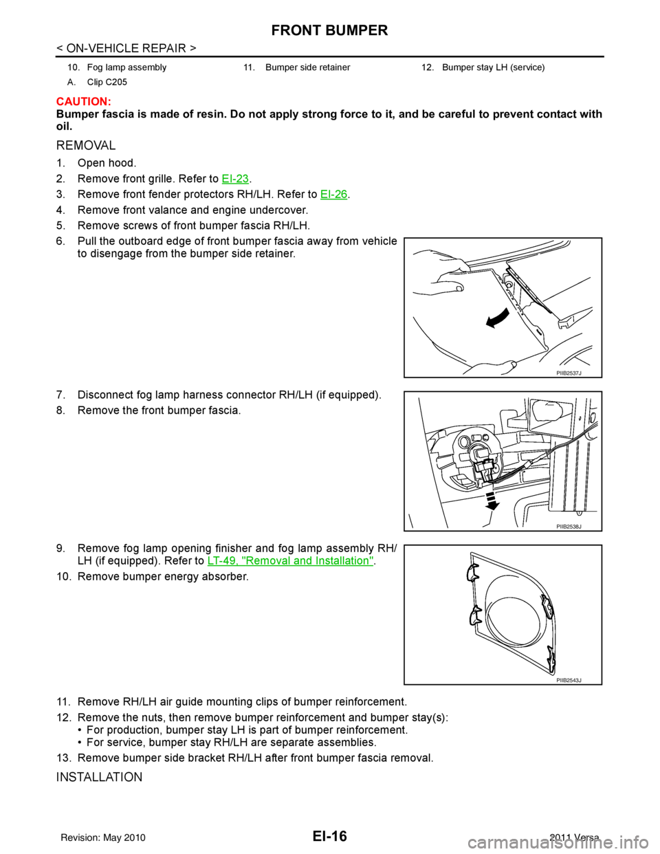
6. Pull the outboard edge of front bumper fascia away from vehicle to disengage from the bumper side retainer.
7. Disconnect fog lamp harness connector RH/LH (if equipped).
8. Remove the front bumper fascia.
9. Remove fog lamp opening finisher and fog lamp assembly RH/ LH (if equipped). Refer to LT-49, "
Removal and Installation".
10. Remove bumper energy absorber.
11. Remove RH/LH air guide mounting clips of bumper reinforcement.
12. Remove the nuts, then remove bumper reinforcement and bumper stay(s): • For production, bumper stay LH is part of bumper reinforcement.
• For service, bumper stay RH/LH are separate assemblies.
13. Remove bumper side bracket RH/LH after front bumper fascia removal.
INSTALLATION
10. Fog lamp assembly 11. Bumper side retainer 12. Bumper stay LH (service)
A. Clip C205
PIIB2537J
PIIB2538J
PIIB2543J
Revision: May 2010 2011 Versa
Page 2353 of 3787
FRONT GRILLEEI-23
< ON-VEHICLE REPAIR >
C
DE
F
G H
J
K L
M A
B
EI
N
O P
FRONT GRILLE
Removal and InstallationINFOID:0000000005929558
REMOVAL
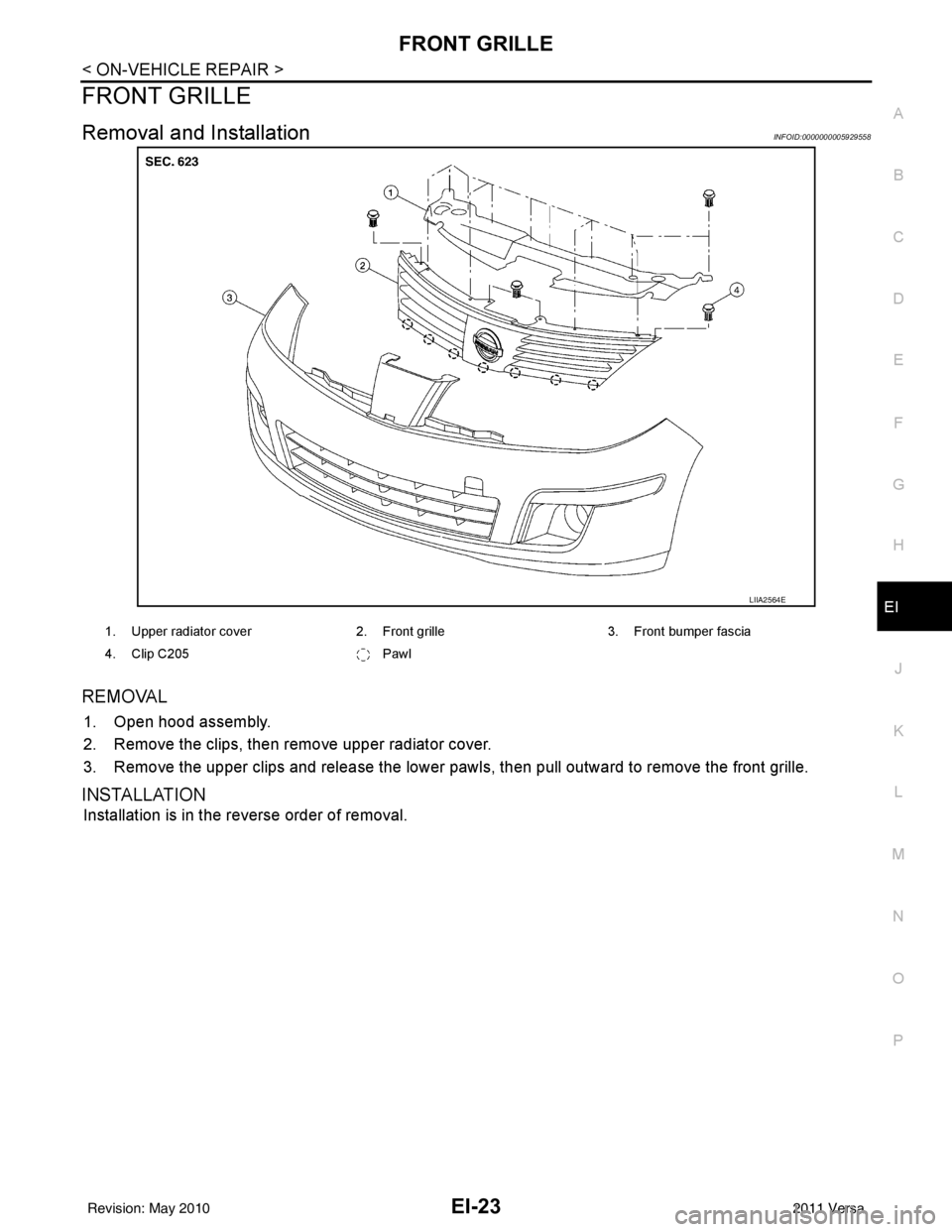
1. Open hood assembly.
2. Remove the clips, then remove upper radiator cover.
3. Remove the upper clips and release the lower pawls, then pull outward to remove the front grille.
INSTALLATION
Installation is in the reverse order of removal.
LIIA2564E
1. Upper radiator cover2. Front grille3. Front bumper fascia
4. Clip C205 Pawl
Revision: May 2010 2011 Versa
Page 2588 of 3787
![NISSAN TIIDA 2011 Service Repair Manual EM-198
< SERVICE INFORMATION >[MR18DE]
ENGINE ASSEMBLY
• Use either 2-pole lift type or separate type lift as
best you can. If board-on type is used for unavoid-
able reasons, support at the rear a](/manual-img/5/57396/w960_57396-2587.png "NISSAN TIIDA 2011 Service Repair Manual EM-198
< SERVICE INFORMATION >[MR18DE]
ENGINE ASSEMBLY
• Use either 2-pole lift type or separate type lift as
best you can. If board-on type is used for unavoid-
able reasons, support at the rear a")
EM-198
< SERVICE INFORMATION >[MR18DE]
ENGINE ASSEMBLY
• Use either 2-pole lift type or separate type lift as
best you can. If board-on type is used for unavoid-
able reasons, support at the rear axle jacking point with a transmission jack or similar tool before
starting work, in preparation for the backward shift of center of gravity.
• For supporting points for lifting and jacking point at rear axle, refer to GI-38, "
Garage Jack and
Safety Stand and 2-Pole Lift".
REMOVAL
Remove the engine and the transaxle assembly from t he vehicle downward. Separate the engine and the tran-
saxle.
1. Remove engine under cover. Refer to EI-15, "
Removal and Installation".
2. Drain engine coolant from radiator. Refer to CO-36, "
Changing Engine Coolant".
CAUTION:
• Perform this step when the engine is cold.
• Do not spill engine coolant on drive belt.
3. Drain clutch fluid (M/T models). Refer to CL-9, "
Air Bleeding Procedure".
4. Remove front fender protector (RH and LH). Refer to EI-26
.
5. Remove exhaust front tube. Refer to EX-10
.
6. Remove drive shafts (LH and RH) from steering knuckle. Refer to FA X - 9
.
7. Remove transaxle joint bolts which pierce at oil pan (upper) lower rear side. Refer to AT-233
(A/T models),
CVT-180, "
Removal and Installation" (CVT models) or MT-61, "Removal and Installation" (M/T models).
8. Remove rear torque rod (1). NOTE:
A/T model shown CVT and M/T models similar.
9. Remove hood assembly. Refer to BL-13
.
10. Remove cowl top cover and cowl top extension assembly. Refer to EI-24
.
11. Release fuel pressure. Refer to EC-582, "
Fuel Pressure Check".
12. Remove battery and battery tray. Refer to SC-5
.
13. Remove drive belt; Refer to EM-132, "
Component".
14. Remove engine room cover.
15. Remove air duct and air cleaner case assembly. Refer to EM-135
.
16. Remove cooling fan assembly. Refer to CO-44, "
Removal and Installation".
17. Remove radiator hose (upper and lower). Refer to CO-40
.
18. Disconnect A/T fluid cooler hoses or CVT water hoses. Refer to CO-40, "
Component" (A/T) or CVT-175,
"WATER HOSE : Exploded View" (CVT).
NOTE:
Cap or plug opening(s) to prevent fluid from spilling.
19. Disconnect all connections of engine harness around the engine mounting insulator (LH), and then tem- porarily secure the engine harness into the engine side.
CAUTION:
Protect connectors using a resin bag to protect against foreign materials during the operation.
20. Disconnect fuel feed hose at engine side. Refer to EM-154, "
Component".
NOTE:
Cap or plug opening(s) to revent fluid from spilling.
21. Disconnect heater hoses. Refer to CO-50, "
Component".
NOTE:
Cap or plug opening(s) to revent fluid from spilling.
LBIA0460E
Revision: May 2010 2011 Versa