2011 NISSAN TIIDA alarm
[x] Cancel search: alarmPage 743 of 3787

VEHICLE SECURITY (THEFT WARNING) SYSTEMBL-233
< SERVICE INFORMATION >
C
DE
F
G H
J
K L
M A
B
BL
N
O P
CONSULT-III APPLICATION ITEM
Work Support
Data Monitor
* : With remote keyless entry system
** : With Intelligent Key system
Active Test
Test Item Description
SECURITY ALARM SET This mode can confirm and change security alarm ON-OFF setting.
THEFT ALM TRG The switch which triggered vehicle security alarm is recorded. This mode is able to confirm and
erase the record of vehicle security alarm. The trigger data can be erased by touching “CLEAR” on
CONSULT-III screen.
Monitored Item
Description
IGN ON SW Indicates [ON/OFF] condition of ignition switch.
ACC ON SW Indicates [ON/OFF] condition of ignition switch in ACC position.
KEYLESS LOCK* Indicates [ON/OFF] condition of lock signal from keyfob.
KEYLESS UNLOCK* Indicates [ON/OFF] condition of unlock signal from keyfob.
I-KEY LOCK** Indicates [ON/OFF] condition of lock signal from keyfob.
I-KEY UNLOCK** Indicates [ON/OFF] condition of unlock signal from keyfob.
TRNK OPNR SW Indicates [ON/OFF] condition of trunk opener switch.
TRUNK CYL SW Indicates [ON/OFF] condition of trunk key cylinder switch.
TRNK OPN MNTR Indicates [ON/OFF] condition of trunk lid status.
DOOR SW-DR Indicates [ON/OFF] condition of front door switch LH.
DOOR SW-AS Indicates [ON/OFF] condition of front door switch RH.
DOOR SW-RR Indicates [ON/OFF] condition of rear door switch RH.
DOOR SW-RL Indicates [ON/OFF] condition of rear door switch LH.
BACK DOOR SW Indicates [ON/OFF] condition of back door switch.
KEY CYL LK-SW Indicates [ON/OFF] condition of lock signal from key cylinder switch.
KEY CYL UN-SW Indicates [ON/OFF] condition of unlock signal from key cylinder switch.
CDL LOCK SW Indicates [ON/OFF] condition of lock signal from door lock/unlock switch LH and RH.
CDL UNLOCK SW Indicates [ON/OFF] condition of unlock signal from door lock/unlock switch LH and RH.
Test Item Description
THEFT IND This test is able to check security indicator lamp operation. The lamp will be turned on when “ON”
on CONSULT-III screen is touched.
VEHICLE SECURITY HORN This test is able to check vehicle security horn operation. The horns will be activated for 0.5 sec-
onds after “ON” on CONSULT-III screen is touched.
HEADLAMP (HI) This test is able to check vehicle security lamp operation. The headlamps will be activated for 0.5
seconds after “ON” on CONSULT-III screen is touched.
Revision: May 2010
2011 Versa
Page 744 of 3787

BL-234
< SERVICE INFORMATION >
VEHICLE SECURITY (THEFT WARNING) SYSTEM
Trouble Diagnosis
INFOID:0000000005929419
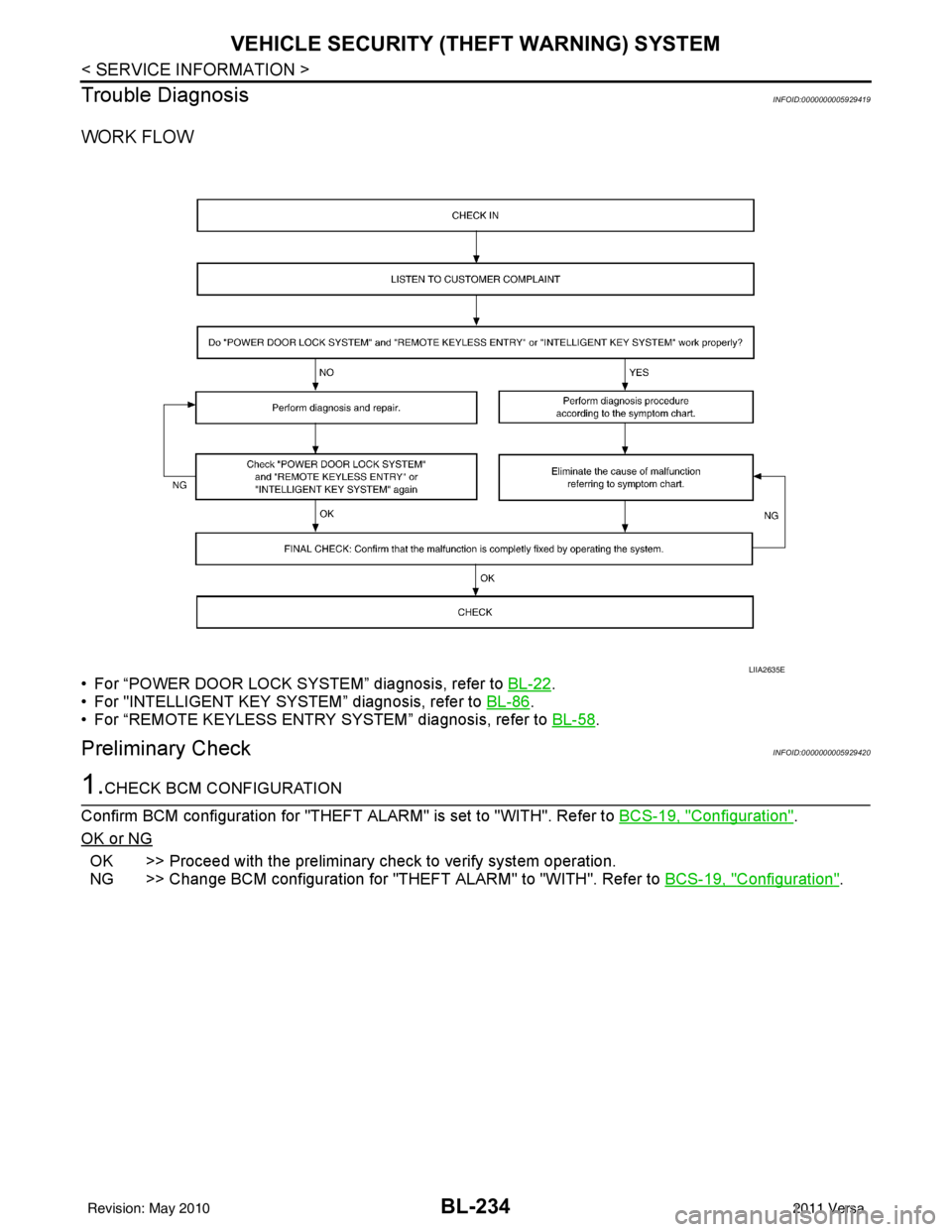
WORK FLOW
• For “POWER DOOR LOCK SYSTEM” diagnosis, refer to BL-22.
• For "INTELLIGENT KEY SYSTEM” diagnosis, refer to BL-86
.
• For “REMOTE KEYLESS ENTRY SYSTEM” diagnosis, refer to BL-58
.
Preliminary CheckINFOID:0000000005929420
1.CHECK BCM CONFIGURATION
Confirm BCM configuration for "THEFT ALARM" is set to "WITH". Refer to BCS-19, "
Configuration".
OK or NG
OK >> Proceed with the preliminary check to verify system operation.
NG >> Change BCM configuration for "THEFT ALARM" to "WITH". Refer to BCS-19, "
Configuration".
LIIA2635E
Revision: May 2010 2011 Versa
Page 746 of 3787

BL-236
< SERVICE INFORMATION >
VEHICLE SECURITY (THEFT WARNING) SYSTEM
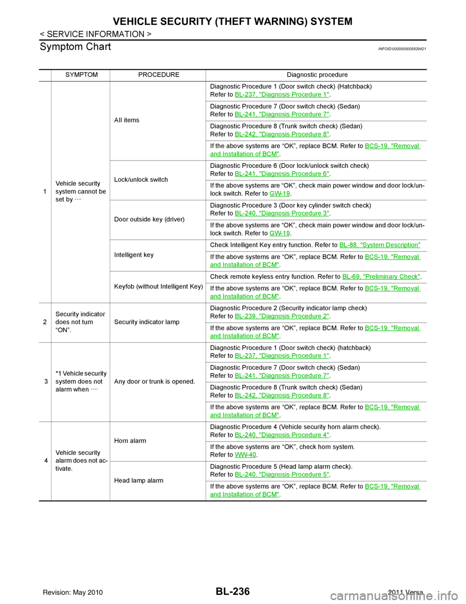
Symptom Chart
INFOID:0000000005929421
SYMPTOM PROCEDURE Diagnostic procedure
1 Vehicle security
system cannot be
set by ···· AII items
Diagnostic Procedure 1 (Door switch check) (Hatchback)
Refer to
BL-237, "
Diagnosis Procedure 1".
Diagnostic Procedure 7 (Door switch check) (Sedan)
Refer to BL-241, "
Diagnosis Procedure 7".
Diagnostic Procedure 8 (Trunk switch check) (Sedan)
Refer to BL-242, "
Diagnosis Procedure 8".
If the above systems are “OK”, replace BCM. Refer to BCS-19, "
Removal
and Installation of BCM".
Lock/unlock switch Diagnostic Procedure 6 (Door lock/unlock switch check)
Refer to
BL-241, "
Diagnosis Procedure 6".
If the above systems are “OK”, check main power window and door lock/un-
lock switch. Refer to GW-19
.
Door outside key (driver) Diagnostic Procedure 3 (Door key cylinder switch check)
Refer to
BL-240, "
Diagnosis Procedure 3".
If the above systems are “OK”, check main power window and door lock/un-
lock switch. Refer to GW-19
.
Intelligent key Check Intelligent Key entry function. Refer to
BL-88, "
System Description"
If the above systems are “OK”, replace BCM. Refer to BCS-19, "Removal
and Installation of BCM".
Keyfob (without Intelligent Key) Check remote keyless entry function. Refer to
BL-69, "
Preliminary Check".
If the above systems are “OK”, replace BCM. Refer to BCS-19, "
Removal
and Installation of BCM".
2 Security indicator
does not turn
“ON”.
Security indicator lamp Diagnostic Procedure 2 (Security indicator lamp check)
Refer to
BL-239, "
Diagnosis Procedure 2".
If the above systems are “OK”, replace BCM. Refer to BCS-19, "
Removal
and Installation of BCM".
3 *1 Vehicle security
system does not
alarm when ····
Any door or trunk is opened. Diagnostic Procedure 1 (Door switch check) (hatchback)
Refer to
BL-237, "
Diagnosis Procedure 1".
Diagnostic Procedure 7 (Door switch check) (Sedan)
Refer to BL-241, "
Diagnosis Procedure 7".
Diagnostic Procedure 8 (Trunk switch check) (Sedan)
Refer to BL-242, "
Diagnosis Procedure 8".
If the above systems are “OK”, replace BCM. Refer to BCS-19, "
Removal
and Installation of BCM".
4 Vehicle security
alarm does not ac-
tivate. Horn alarm
Diagnostic Procedure 4 (Vehicle security horn alarm check).
Refer to
BL-240, "
Diagnosis Procedure 4".
If the above systems are “OK”, check horn system.
Refer to WW-40
.
Head lamp alarm Diagnostic Procedure 5 (Head lamp alarm check).
Refer to
BL-240, "
Diagnosis Procedure 5".
If the above systems are “OK”, replace BCM. Refer to BCS-19, "
Removal
and Installation of BCM".
Revision: May 2010 2011 Versa
Page 750 of 3787

BL-240
< SERVICE INFORMATION >
VEHICLE SECURITY (THEFT WARNING) SYSTEM
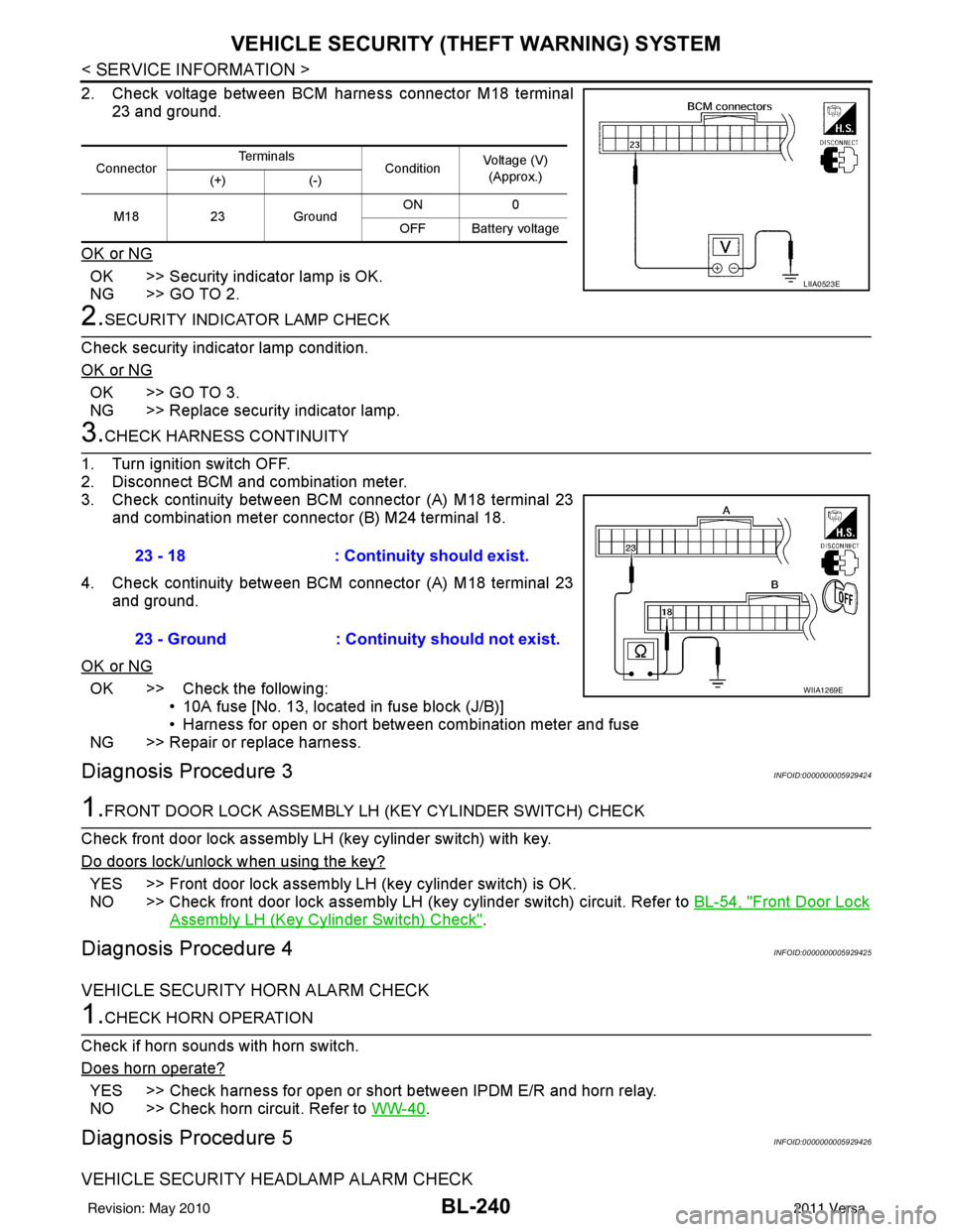
2. Check voltage between BCM harness connector M18 terminal
23 and ground.
OK or NG
OK >> Security indicator lamp is OK.
NG >> GO TO 2.
2.SECURITY INDICATOR LAMP CHECK
Check security indicator lamp condition.
OK or NG
OK >> GO TO 3.
NG >> Replace security indicator lamp.
3.CHECK HARNESS CONTINUITY
1. Turn ignition switch OFF.
2. Disconnect BCM and combination meter.
3. Check continuity between BCM connector (A) M18 terminal 23 and combination meter connector (B) M24 terminal 18.
4. Check continuity between BCM connector (A) M18 terminal 23 and ground.
OK or NG
OK >> Check the following: • 10A fuse [No. 13, located in fuse block (J/B)]
• Harness for open or short between combination meter and fuse
NG >> Repair or replace harness.
Diagnosis Procedure 3INFOID:0000000005929424
1.FRONT DOOR LOCK ASSEMBLY LH (KEY CYLINDER SWITCH) CHECK
Check front door lock assembly LH (key cylinder switch) with key.
Do doors lock/unlock when using the key?
YES >> Front door lock assembly LH (key cylinder switch) is OK.
NO >> Check front door lock assembly LH (key cylinder switch) circuit. Refer to BL-54, "
Front Door Lock
Assembly LH (Key Cylinder Switch) Check".
Diagnosis Procedure 4INFOID:0000000005929425
VEHICLE SECURITY HORN ALARM CHECK
1.CHECK HORN OPERATION
Check if horn sounds with horn switch.
Does horn operate?
YES >> Check harness for open or short between IPDM E/R and horn relay.
NO >> Check horn circuit. Refer to WW-40
.
Diagnosis Procedure 5INFOID:0000000005929426
VEHICLE SECURITY HEADLAMP ALARM CHECK
ConnectorTe r m i n a l s
ConditionVoltage (V)
(Approx.)
(+) (-)
M18 23Ground ON
0
OFF Battery voltage
LIIA0523E
23 - 18 : Continuity should exist.
23 - Ground : Continuity should not exist.
WIIA1269E
Revision: May 2010 2011 Versa
Page 751 of 3787

VEHICLE SECURITY (THEFT WARNING) SYSTEMBL-241
< SERVICE INFORMATION >
C
DE
F
G H
J
K L
M A
B
BL
N
O P
1.CHECK VEHICLE SECURITY H EADLAMP ALARM OPERATION
Check if headlamps operate with lighting switch.
Do headlamps come on when turning switch ON?
YES >> Headlamp alarm is OK.
NO >> Check headlamp system. Refer to LT- 5
or LT- 2 7.
Diagnosis Procedure 6INFOID:0000000005929427
DOOR LOCK/UNLOCK SWITCH CHECK
1.CHECK DOOR LOCK/UNLOCK SWITCH INPUT SIGNAL
Check if power door lock operates with door lock/unlock switch.
Do doors lock/unlock when using each door lock/unlock switch?
YES >> Door lock/unlock switch is OK.
NO >> Refer to BL-49, "
Door Lock and Unlock Switch Check".
Diagnosis Procedure 7INFOID:0000000005929428
DOOR SWITCH CHECK (SEDAN)
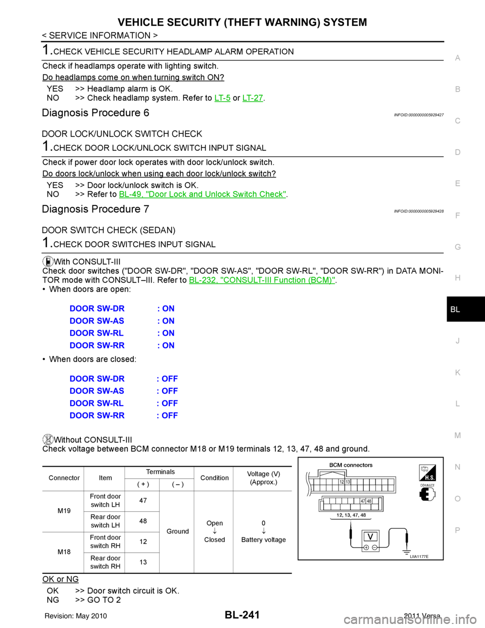
1.CHECK DOOR SWITCHES INPUT SIGNAL
With CONSULT-III
Check door switches ("DOOR SW-DR", "DOOR SW-AS" , "DOOR SW-RL", "DOOR SW-RR") in DATA MONI-
TOR mode with CONSULT–III. Refer to BL-232, "
CONSULT-III Function (BCM)".
• When doors are open:
• When doors are closed:
Without CONSULT-III
Check voltage between BCM connector M18 or M19 terminals 12, 13, 47, 48 and ground.
OK or NG
OK >> Door switch circuit is OK.
NG >> GO TO 2 DOOR SW-DR : ON
DOOR SW-AS : ON
DOOR SW-RL : ON
DOOR SW-RR : ON
DOOR SW-DR : OFF
DOOR SW-AS : OFF
DOOR SW-RL : OFF
DOOR SW-RR : OFF
Connector Item
Te r m i n a l s
ConditionVoltage (V)
(Approx.)
( + ) ( – )
M19 Front door
switch LH 47
Ground Open
↓
Closed 0
↓
Battery voltage
Rear door
switch LH 48
M18 Front door
switch RH 12
Rear door
switch RH 13
LIIA1177E
Revision: May 2010
2011 Versa
Page 2874 of 3787
![NISSAN TIIDA 2011 Service Repair Manual LAN-28
< SERVICE INFORMATION >[CAN]
CAN COMMUNICATION SYSTEM
*1: A/T models
*2: CVT models
*3: Models with VDC
*4: Models for Canada
*5: Models for USA
*6: Models without ABS
NOTE:
CAN data of the air NISSAN TIIDA 2011 Service Repair Manual LAN-28
< SERVICE INFORMATION >[CAN]
CAN COMMUNICATION SYSTEM
*1: A/T models
*2: CVT models
*3: Models with VDC
*4: Models for Canada
*5: Models for USA
*6: Models without ABS
NOTE:
CAN data of the air](/manual-img/5/57396/w960_57396-2873.png)
LAN-28
< SERVICE INFORMATION >[CAN]
CAN COMMUNICATION SYSTEM
*1: A/T models
*2: CVT models
*3: Models with VDC
*4: Models for Canada
*5: Models for USA
*6: Models without ABS
NOTE:
CAN data of the air bag diagnosis sensor unit is not used by usual service work, thus it is omitted.
KEY warning lamp signal
T R
LOCK warning lamp signal T R
Panic alarm request signal RT
Fuel level sensor signal RT
Overdrive control switch signal TR R
Parking brake switch signal
*3TR
Stop lamp switch signal T R R
Vehicle speed signal RRRR T
RRR T R
R
*6T*6
Steering angle sensor signal*3TR
ABS warning lamp signal RT
Brake warning lamp signal RT
SLIP indicator lamp signal
*3RT
VDC OFF indicator lamp signal
*3RT
VDC warning lamp signal
*3RT
A/T check indicator signal RT
A/T self-diagnosis signal R T
Input speed signal R T
OD OFF indicator signal RT
Output shaft revolution signal R T T
Shift position indicator signal R
R
*3TT
CVT self-diagnosis signal R T
Input shaft revolution signal R T
OD OFF indicator signal RT
Front wiper stop position signal R T
High beam status signal R T
Low beam status signal R T
Oil pressure switch signal R RR T
Rear window defogger control signal R T
Signal name/Connecting unit
ECM
BCM
EPS
I-KEY M&A
STRG ABS
TCM
*1
TCM
*2
IPDM-E
Revision: May 2010 2011 Versa
Page 3045 of 3787

HEADLAMP (FOR USA)LT-13
< SERVICE INFORMATION >
C
DE
F
G H
I
J
L
M A
B
LT
N
O P
WORK SUPPORT
Display Item List
CONSULT-III Function (IPDM E/R)INFOID:0000000006227567
CONSULT-III can display each diagnostic item using the diagnostic test modes shown following.
SELF-DIAGNOSTIC RESULTS
Display Item List
Blower fan switch sig-
nal
Air conditioner switch
signal AIR CONDITION-
ER
××
Intelligent Key INTELLIGENT
KEY ×
Combination switch COMB SW ×
NVIS (NATS) IMMU ××
Interior lamp battery
saver BATTERY SAV-
ER
××
×
Back door/Trunk TRUNK ××
Theft alarm THEFT ALARM×× ×
Retained accessory
power control RETAINED PWR
×× ×
Oil pressure switch SIGNAL BUFFER ××
Low tire pressure moni-
tor AIR PRESSURE
MONITOR
××
× ×
Panic alarm PANIC ALARM ×
System and item
CONSULT-III
display Diagnostic test mode (Inspection by part)
WORK
SUPPORT SELF
DIAGNOS-
TIC RE-SULT CAN DIAG
SUPPORT MNTR DATA
MONITOR ECU
IDENTI-
FICA-TION AC-
TIVE
TEST CON-
FIGU-
RATION
Item Description
RESET SETTING VALUE Return a value set with WORK SUPPORT of each system to a default value in factory shipment.
IPDM E/R diagnostic Mode Description
SELF-DIAG RESULTS Displays IPDM E/R self-diagnosis results. DATA MONITOR Displays IPDM E/R input/output data in real time.
CAN DIAG SUPPORT MNTR The result of transmit/receive diagnosis of CAN communication can be read. ACTIVE TEST Operation of electrical loads can be checked by sending drive signal to them.
Revision: May 2010 2011 Versa
Page 3136 of 3787

LT-104
< SERVICE INFORMATION >
INTERIOR ROOM LAMP
1 : With remote keyless entry system
2: With Intelligent Key system
WORK SUPPORT
Display Item List
Interior Room Lamp Control Does Not Operate (With Map Lamp)INFOID:0000000005929146
1.CHECK EACH SWITCH
Select "BCM" on CONSULT-III. With "INT LAMP" data monitor, make sure switches listed in display item list
turn ON-OFF linked with switch operation. Refer to BCS-17, "
CONSULT-III Function (BCM)" for switches and
their functions.
OK or NG
OK >> GO TO 2.
NG >> Inspect malfunctioning switch system.
2.ACTIVE TEST
1. Select “BCM” on CONSULT-III. Select “INT LAMP" active test.
2. When room lamp switch is in DOOR position, make sure room lamp operates.
OK or NG
OK >> Replace BCM. Refer to BCS-19, "Removal and Installation of BCM" .
NG >> GO TO 3.
3.CHECK ROOM LAMP INPUT VOLTAGE
Blower fan switch sig-
nal
Air conditioner switch
signal AIR CONDITION-
ER
××
Combination switch COMB SW ×
NVIS (NATS) IMMU ××
Interior lamp battery
saver BATTERY SAV-
ER
××
×
Back door/Trunk TRUNK/BACK
DOOR ××
Theft alarm THEFT ALM×× ×
Retained accessory
power control RETAINED PWR
×× ×
Oil pressure swit ch SIGNAL BUFFER ××
Panic alarm PANIC ALARM ×
Remote keyless entry
system
1MULTI REMOTE
ENTRY ××
×
System and item
CONSULT-III dis-
play Diagnostic test mode (Inspection by part)
WORK
SUPPORT SELF
−
DIAG RE-
SULTS CAN DIAG
SUPPORT
MNTR DATA
MONITOR ECU
PA R T
NUMBER AC-
TIVE
TEST CON-
FIGU-
RATION
Item Description
RESET SETTING VALUE Return a value set with WORK SUPPORT of each system to a default value in factory shipment.
Room lamp should operate.
Revision: May 2010 2011 Versa