2011 NISSAN TIIDA Daytime light
[x] Cancel search: Daytime lightPage 3071 of 3787

HEADLAMP (FOR CANADA) - DAYTIME LIGHT SYSTEM -
LT-39
< SERVICE INFORMATION >
C
D E
F
G H
I
J
L
M A
B
LT
N
O P
2. Turn bulb socket counterclockwise and unlock from front combination lamp assembly.
3. Remove bulb from its socket.
FRONT TURN SIGNAL LAMP
1. Turn lighting switch OFF.
2. Turn bulb socket counterclockwise and unlock from front combination lamp assembly.
3. Remove bulb from its socket.
Removal and InstallationINFOID:0000000005929063
REMOVAL
1. Disconnect the negative battery terminal.
2. Remove front bumper fascia. Refer to EI-15
.
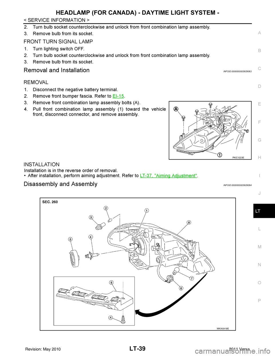
3. Remove front combination lamp assembly bolts (A).
4. Pull front combination lamp assembly (1) toward the vehicle front, disconnect connector, and remove assembly.
INSTALLATION
Installation is in the reverse order of removal.
• After installation, perform aiming adjustment. Refer to LT-37, "
Aiming Adjustment".
Disassembly and AssemblyINFOID:0000000005929064
PKIC1223E
WKIA5418E
Revision: May 2010 2011 Versa
Page 3072 of 3787

LT-40
< SERVICE INFORMATION >
HEADLAMP (FOR CANADA) - DAYTIME LIGHT SYSTEM -
DISASSEMBLY
1. Remove back cover.
2. Unlock retaining spring and remove bulb (High/Low).
3. Turn parking (clearance) lamp bulb socket counterclockwise and unlock it.
4. Remove parking (clearance) lamp bulb from its socket.
5. Turn front turn signal lamp bulb socket counterclockwise and unlock it.
6. Remove front turn signal lamp bulb from its socket.
7. Remove the bumper stay.
ASSEMBLY
Assembly is in the reverse order of disassembly.
CAUTION:
• After installing bulb, be sure to install plastic cap secure ly to insure water tight seal.
1. Retaining spring 2. Parking lamp bulb3. Parking lamp bulb socket
4. Halogen headlamp bulb (High/Low) 5. Headlamp bulb back cover 6. Front turn signal lamp bulb socket
7. Front turn signal lamp bulb 8. Front combination lamp assembly 9. Bumper stay
A. Screw
Revision: May 2010 2011 Versa
Page 3437 of 3787

IPDM E/R (INTELLIGENT POWER DISTRIBUTION MODULE ENGINE ROOM)
PG-17
< SERVICE INFORMATION >
C
D E
F
G H
I
J
L
M A
B
PG
N
O P
IPDM E/R (INTELLIGENT POWER DISTRIBUTION MODULE ENGINE
ROOM)
System DescriptionINFOID:0000000005928343
• IPDM E/R (Intelligent Power Distribution Module Engi ne Room) integrates the relay box and fuse block
which were originally placed in engine compartment. It controls integrated relays via IPDM E/R control cir-
cuits.
• IPDM E/R-integrated control circuits perform ON-OFF operation of relays, CAN communication control, oil pressure switch signal reception, etc.
• It controls operation of each electrical co mponent via ECM, BCM and CAN communication lines.
CAUTION:
None of the IPDM E/R integr ated relays can be removed.
SYSTEMS CONTROLLED BY IPDM E/R
1. Lamp control
Using CAN communication lines, it receives signals from the BCM and controls the following lamps:
• Headlamps (High, Low)
• Parking lamps
• Tail and license plate lamps
• Front fog lamps
2. Wiper control Using CAN communication lines, it receives signals from the BCM and controls the front wipers.
3. Rear window defogger relay control Using CAN communication lines, it receives signals from the BCM and controls the rear window defogger
relay.
4. A/C compressor control Using CAN communication lines, it receives signal s from the ECM and controls the A/C compressor
(magnet clutch).
5. Starter control Using CAN communication lines, it receives signals from the BCM and controls the starter relay.
6. Cooling fan control Using CAN communication lines, it receives signals from the ECM and controls the cooling fan relays.
7. Horn control Using CAN communication lines, it receives signals from the BCM and controls the horn relay.
8. Daytime light system control (Canada only) Using CAN communication lines, it receives signals from the BCM and controls the daytime light relay.
CAN COMMUNICATION LINE CONTROL
With CAN communication, by connecting each control unit using two communication lines (CAN L-line, CAN
H-line), it is possible to transmit a maximum amount of information with minimum wiring. Each control unit can
transmit and receive data, and reads necessary information only.
1. Fail-safe control • When CAN communication with other control units is impossible, IPDM E/R performs fail-safe control.
After CAN communication returns to normal operation, it also returns to normal control.
• Operation of control parts by IPDM E/ R during fail-safe mode is as follows:
Controlled system Fail-safe mode
Headlamp • With the ignition switch ON, headlamp low relay is ON, headlamp high relays are OFF, and
daytime light system (Canada only) is OFF.
• With the ignition switch OFF, the headlamp relays are OFF.
Tail, license plate and parking lamps • With the ignition switch ON, the tail lamp relay is ON. • With the ignition switch OFF, the tail lamp relay is OFF.
Cooling fan • With the ignition switch ON, cooling fan relay-1, relay-2, and relay-3 are ON.
• With the ignition switch OFF, all cooling fan relays are OFF.
Front wiper Until the ignition switch is turned off, the front wiper relays remain in the same status they
were in just before fail
−safe control was initiated.
Revision: May 2010 2011 Versa
Page 3440 of 3787

PG-20
< SERVICE INFORMATION >
IPDM E/R (INTELLIGENT POWER DISTRIBUTION MODULE ENGINE ROOM)
*1 Perform monitoring of IPDM E/R data with the ignition switch ON. When the ignition switch is in ACC position, display may no t be cor-
rect.
*2 This item is displayed, but does not function.
CAN DIAG SUPPORT MNTR
Refer to LAN-9, "Description" .
ACTIVE TEST
Display Item List
Auto Active TestINFOID:0000000005928347
DESCRIPTION
• In auto active test mode, operation inspection can be performed when IPDM E/R sends a drive signal to the
following systems:
- Rear window defogger
- Front wipers
- Tail, license and parking lamps
- Daytime lamp system (Canada only)
- Front fog lamps
- Headlamps (High, Low)
- A/C compressor (magnet clutch)
- Cooling fan
OPERATION PROCEDURE
1. Close hood and front door RH, and lift wiper arms away from windshield (to prevent glass damage by wiper operation).
NOTE:
When auto active test is performed with hood opened, sprinkle water on windshield beforehand.
2. Turn ignition switch OFF.
3. Turn ignition switch ON and, within 20 seconds, pres s front door switch LH 10 times. Then turn ignition
switch OFF.
4. Turn ignition switch ON within 10 seconds after ignition switch OFF.
5. When auto active test mode is actuated, horn chirps once.
6. After a series of operations is repeated three times, auto active test is completed.
Theft warning
horn request THFT HRN REQ ON/OFF
XX Signal status input from BCM
Horn chirp HORN CHIRP ON/OFF XX Output status of IPDM E/R
Daytime light re-
quest DTRL REQ ON/OFF
XX Signal status input from BCM
Item name
CONSULT-III
screen display Display or unit Monitor item selection
Description
ALL
SIGNALS MAIN
SIGNALS SELECTION
FROM MENU
Test name CONSULT-III screen display Description
Head, tail, fog lamp output EXTERNAL LAMPS With a certain ON-OFF operation (OFF, TAIL, LO, HI, FOG), the front
fog lamp, headlamp low, headlamp high RH, headlamp high LH, and
tail lamp relays can be operated.
Rear defogger output REAR DEFOGGER With a certain ON-OFF operation, the rear defogger relay can be oper-
ated.
Front wiper (HI, LO) output FRONT WIPER With a certain operation (OFF, HI ON, LO ON), the front wiper relays
(Lo, Hi) can be operated.
Cooling fan output MOTOR FAN With a certain operation (1, 2, 3, 4), the cooling fan relays can be oper-
ated.
Horn output HORN With a certain ON-OFF operation, the horn relay can be operated.
Revision: May 2010 2011 Versa
Page 3441 of 3787

IPDM E/R (INTELLIGENT POWER DISTRIBUTION MODULE ENGINE ROOM)
PG-21
< SERVICE INFORMATION >
C
D E
F
G H
I
J
L
M A
B
PG
N
O P
NOTE:
When auto active test mode has to be cancelled halfway, turn ignition switch OFF.
CAUTION:
Be sure to perform BL-44, "
Door Switch Check (Hatchback)" or BL-47, "Door Switch Check
(Sedan)" when the auto active test cannot be performed.
INSPECTION IN AUTO ACTIVE TEST MODE
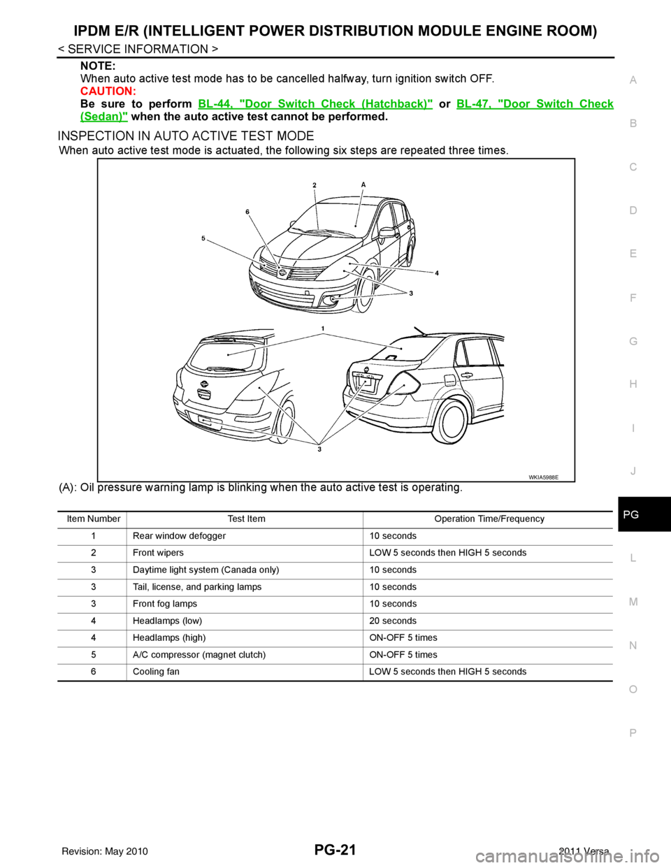
When auto active test mode is actuated, the following six steps are repeated three times.
(A): Oil pressure warning lamp is blinking when the auto active test is operating.
WKIA5988E
Item Number Test Item Operation Time/Frequency
1 Rear window defogger 10 seconds
2 Front wipers LOW 5 seconds then HIGH 5 seconds
3 Daytime light system (Canada only) 10 seconds
3 Tail, license, and parking lamps 10 seconds
3 Front fog lamps 10 seconds
4 Headlamps (low) 20 seconds
4 Headlamps (high) ON-OFF 5 times
5 A/C compressor (magnet clutch) ON-OFF 5 times
6 Cooling fan LOW 5 seconds then HIGH 5 seconds
Revision: May 2010 2011 Versa
Page 3442 of 3787

PG-22
< SERVICE INFORMATION >
IPDM E/R (INTELLIGENT POWER DISTRIBUTION MODULE ENGINE ROOM)
Concept of Auto Active Test
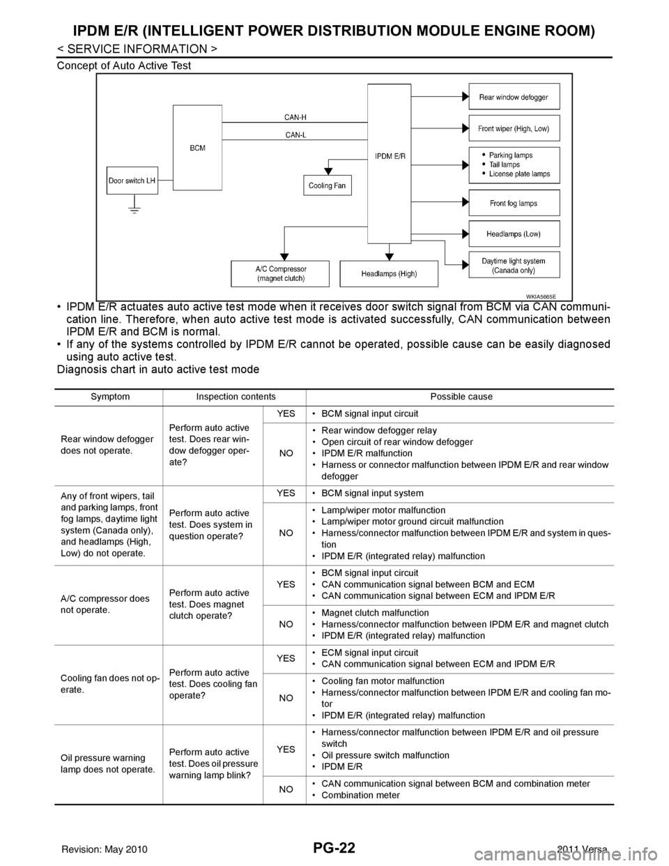
• IPDM E/R actuates auto active test mode when it re ceives door switch signal from BCM via CAN communi-
cation line. Therefore, when auto active test mode is activated successfully, CAN communication between
IPDM E/R and BCM is normal.
• If any of the systems controll ed by IPDM E/R cannot be operated, possible cause can be easily diagnosed
using auto active test.
Diagnosis chart in auto active test mode
WKIA5665E
Symptom Inspection contents Possible cause
Rear window defogger
does not operate. Perform auto active
test. Does rear win-
dow defogger oper-
ate?YES • BCM signal input circuit
NO • Rear window defogger relay
• Open circuit of rear window defogger
•IPDM E/R malfunction
• Harness or connector malfunction between IPDM E/R and rear window
defogger
Any of front wipers, tail
and parking lamps, front
fog lamps, daytime light
system (Canada only),
and headlamps (High,
Low) do not operate. Perform auto active
test. Does system in
question operate?YES • BCM signal input system
NO • Lamp/wiper motor malfunction
• Lamp/wiper motor ground circuit malfunction
• Harness/connector malfunction between IPDM E/R and system in ques-
tion
• IPDM E/R (integrated relay) malfunction
A/C compressor does
not operate. Perform auto active
test. Does magnet
clutch operate?YES
• BCM signal input circuit
• CAN communication signal between BCM and ECM
• CAN communication signal between ECM and IPDM E/R
NO • Magnet clutch malfunction
• Harness/connector malfunction between IPDM E/R and magnet clutch
• IPDM E/R (integrated relay) malfunction
Cooling fan does not op-
erate. Perform auto active
test. Does cooling fan
operate?YES
• ECM signal input circuit
• CAN communication signal between ECM and IPDM E/R
NO • Cooling fan motor malfunction
• Harness/connector malfunction between IPDM E/R and cooling fan mo-
tor
• IPDM E/R (integrated relay) malfunction
Oil pressure warning
lamp does not operate. Perform auto active
test. Does oil pressure
warning lamp blink?YES
• Harness/connector malfunction between IPDM E/R and oil pressure
switch
• Oil pressure switch malfunction
•IPDM E/R
NO • CAN communication signal between BCM and combination meter
• Combination meter
Revision: May 2010
2011 Versa
Page 3445 of 3787

IPDM E/R (INTELLIGENT POWER DISTRIBUTION MODULE ENGINE ROOM)
PG-25
< SERVICE INFORMATION >
C
D E
F
G H
I
J
L
M A
B
PG
N
O P
Terminal and Reference Value for IPDM E/RINFOID:0000000005928350
Te r m i n a l Wire
color Signal name Signal
input/
output Measuring condition
Reference value
(Approx.)
Ignition
switch Operation or condition
1 R Battery power supply Input OFF —Battery voltage
2 G Battery power supply Input OFF —Battery voltage
3YECM Relay Output— Ignition switch ON or START
Battery voltage
Ignition switch OFF or ACC 0V
4GECM relay Output— Ignition switch ON or START
Battery voltage
Ignition switch OFF or ACC 0V
6R Daytime light relay
control Input ON Daytime light system active. Less than battery voltage
Daytime light system inactive. Battery voltage
7 G ECM relay control Input — Ignition switch ON or START
0V
Ignition switch OFF or ACC Battery voltage
8G Throttle control motor
relay
Output —Ignition switch ON or START
Battery voltage
Ignition switch OFF or ACC 0V
11 W A/C compressor Output ON or
START A/C switch ON or defrost A/C
switch
Battery voltage
A/C switch OFF or defrost A/C
switch 0V
12 O Ignition switch sup-
plied power Input —OFF or ACC
0V
ON or START Battery voltage
14 LG
(M/T) R
(A/T or
CVT) Fuse 49
Output —Ignition switch ON or START
Battery voltage
Ignition switch OFF or ACC 0V
15 V Fuse 50 Output —Ignition switch ON or START
Battery voltage
Ignition switch OFF or ACC 0V
16 BR Fuse 51 Output —Ignition switch ON or START
Battery voltage
Ignition switch OFF or ACC 0V
17 Y Battery power supply Output — —Battery voltage
19 R Starter motor Output START—Battery voltage
20 L
(with A/C)
LG
(with-
out A/
C) Cooling fan relay-1 Output — Conditions correct for cooling
fan low operation.
Battery voltage
Conditions not correct for
cooling fan low operation. 0V
22 G Battery power supply Input — —Battery voltage
23 L Cooling fan relay-2 Input — Conditions correct for cooling
fan high operation
Battery voltage
Conditions not correct for
cooling fan high operation 0V
Revision: May 2010
2011 Versa
Page 3464 of 3787

PG-44
< SERVICE INFORMATION >
HARNESS
Refer to "ENGINE ROOM HARNESS (LH VIEW)" for continuation of engine room harness.
G2 E1 GR/5 : Front wiper motor F2 E33 B/26 : ABS actuator and electric unit (control unit)
C3 E2 B/2 : Front and rear washer motor E2 E37 B/5 : Daytime light relay 1
F5 E4 Y/2 : Crash zone sensor D2 E38 L/5 : Daytime light relay 2
E4 E17 B/3 : Refrigerant pressure sensor E2 E41 — : Ground (ABS)
D2 E24 — : Engine ground C3 E50 W/2 : Washer fluid level switch
C3 E26 B/3 : Front combination lamp RH D1 E52 B/2 : Front wheel sensor RH
C4 E28 B/2 : Front fog lamp RH D2 E54 B/2 : Front combination lamp RH
D3 E30 B/2 : Front combination lamp RH
Revision: May 2010 2011 Versa