2011 NISSAN TIIDA Engine
[x] Cancel search: EnginePage 767 of 3787
NATS (NISSAN ANTI-THEFT SYSTEM)BL-257
< SERVICE INFORMATION >
C
DE
F
G H
J
K L
M A
B
BL
N
O P
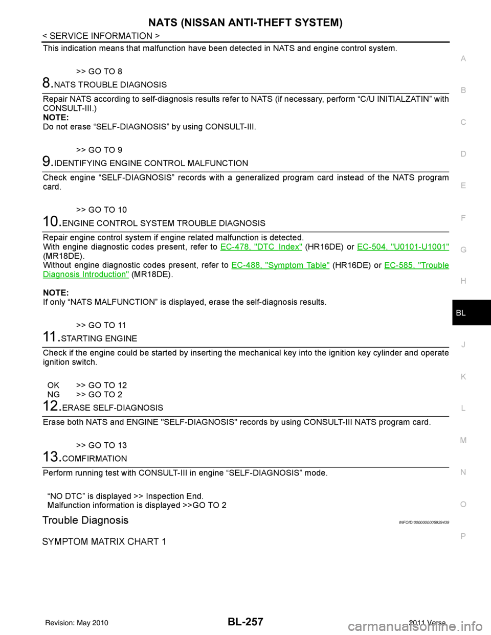
This indication means that malfunction have been detected in NATS and engine control system.
>> GO TO 8
8.NATS TROUBLE DIAGNOSIS
Repair NATS according to self-diagnosis results refer to NATS (if necessary, perform “C/U INITIALZATIN” with
CONSULT-III.)
NOTE:
Do not erase “SELF-DIAGNOSI S” by using CONSULT-III.
>> GO TO 9
9.IDENTIFYING ENGINE CONTROL MALFUNCTION
Check engine “SELF-DIAGNOSIS” records with a general ized program card instead of the NATS program
card.
>> GO TO 10
10.ENGINE CONTROL SYSTEM TROUBLE DIAGNOSIS
Repair engine control system if engine related malfunction is detected.
With engine diagnostic codes present, refer to EC-478, "
DTCIndex" (HR16DE) or EC-504, "U0101-U1001"
(MR18DE).
Without engine diagnostic codes present, refer to EC-488, "
Symptom Table" (HR16DE) or EC-585, "Trouble
Diagnosis Introduction" (MR18DE).
NOTE:
If only “NATS MALFUNCTION” is display ed, erase the self-diagnosis results.
>> GO TO 11
11 .STARTING ENGINE
Check if the engine could be started by inserting the mechanical key into the ignition key cylinder and operate
ignition switch.
OK >> GO TO 12
NG >> GO TO 2
12.ERASE SELF-DIAGNOSIS
Erase both NATS and ENGINE "SELF-DI AGNOSIS" records by using CONSULT-III NATS program card.
>> GO TO 13
13.COMFIRMATION
Perform running test with CONSULT-II I in engine “SELF-DIAGNOSIS” mode.
“NO DTC” is displayed >> Inspection End.
Malfunction information is displayed >>GO TO 2
Trouble DiagnosisINFOID:0000000005929439
SYMPTOM MATRIX CHART 1
Revision: May 2010 2011 Versa
Page 768 of 3787
BL-258
< SERVICE INFORMATION >
NATS (NISSAN ANTI-THEFT SYSTEM)
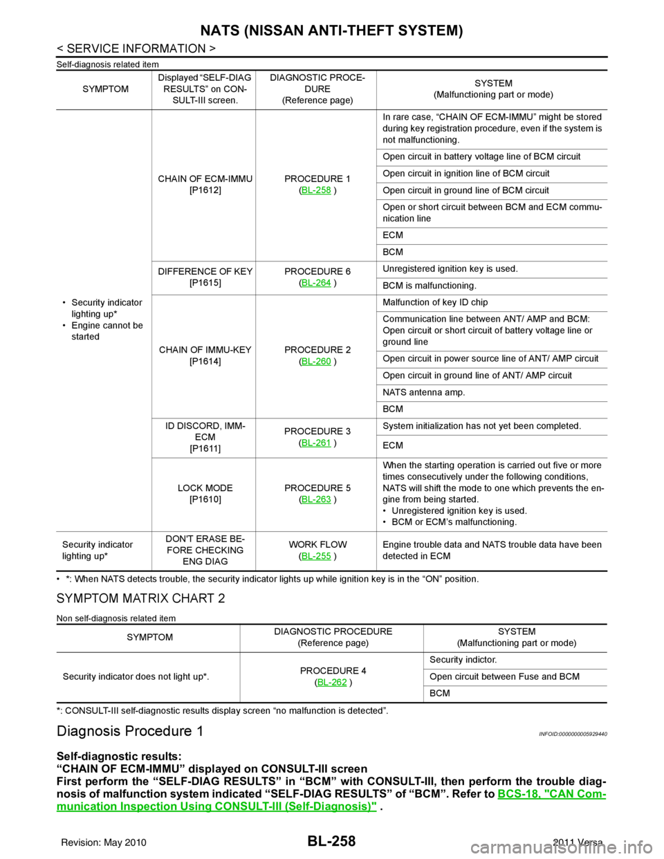
Self-diagnosis related item
• *: When NATS detects trouble, the security indicator lights up while ignition key is in the “ON” position.
SYMPTOM MATRIX CHART 2
Non self-diagnosis related item
*: CONSULT-III self-diagnostic results display screen “no malfunction is detected”.
Diagnosis Procedure 1INFOID:0000000005929440
Self-diagnostic results:
“CHAIN OF ECM-IMMU” displayed on CONSULT-III screen
First perform the “SELF-DIAG RESU LTS” in “BCM” with CONSULT-III, then perform the trouble diag-
nosis of malfunction system indicated “SELF-DIAG RESULTS” of “BCM”. Refer to BCS-18, "
CAN Com-
munication Inspection Using CONSULT-III (Self-Diagnosis)" .
SYMPTOMDisplayed “SELF-DIAG
RESULTS” on CON- SULT-III screen. DIAGNOSTIC PROCE-
DURE
(Reference page) SYSTEM
(Malfunctioning part or mode)
• Security indicator lighting up*
• Engine cannot be started CHAIN OF ECM-IMMU
[P1612] PROCEDURE 1
(BL-258
) In rare case, “CHAIN OF ECM-IMMU” might be stored
during key registration procedure, even if the system is
not malfunctioning.
Open circuit in battery voltage line of BCM circuit
Open circuit in ignition line of BCM circuit
Open circuit in ground line of BCM circuit
Open or short circuit between BCM and ECM commu-
nication line
ECM
BCM
DIFFERENCE OF KEY [P1615] PROCEDURE 6
(BL-264
) Unregistered ignition key is used.
BCM is malfunctioning.
CHAIN OF IMMU-KEY [P1614] PROCEDURE 2
(BL-260
) Malfunction of key ID chip
Communication line between ANT/ AMP and BCM:
Open circuit or short circuit of battery voltage line or
ground line
Open circuit in power source line of ANT/ AMP circuit
Open circuit in ground line of ANT/ AMP circuit
NATS antenna amp.
BCM
ID DISCORD, IMM- ECM
[P1611] PROCEDURE 3
(BL-261
) System initialization has not yet been completed.
ECM
LOCK MODE [P1610] PROCEDURE 5
(BL-263
) When the starting operation is carried out five or more
times consecutively under the following conditions,
NATS will shift the mode to one which prevents the en-
gine from being started.
• Unregistered ignition key is used.
• BCM or ECM’s malfunctioning.
Security indicator
lighting up* DON'T ERASE BE-
FORE CHECKING ENG DIAG WORK FLOW
(BL-255
) Engine trouble data and NATS trouble data have been
detected in ECM
SYMPTOM
DIAGNOSTIC PROCEDURE
(Reference page) SYSTEM
(Malfunctioning part or mode)
Security indicator does not light up*. PROCEDURE 4
(BL-262
) Security indictor.
Open circuit between Fuse and BCM
BCM
Revision: May 2010
2011 Versa
Page 770 of 3787
BL-260
< SERVICE INFORMATION >
NATS (NISSAN ANTI-THEFT SYSTEM)
5.REPLACE BCM
1. Replace BCM. Refer to BCS-19, "
Removal and Installation of BCM".
2. Perform initialization with CONSULT-III.
For initialization, refer to “CONSULT-III Operation Manual NATS”.
Does the engine start?
Yes >> BCM is malfunctioning. • Replace BCM. Refer to BCS-19, "
Removal and Installation of BCM" .
• Perform initialization with CONSULT-III
• For initialization, refer to “CONSULT-III Operation Manual NATS”
No >> ECM is malfunctioning. • Replace ECM.
• Perform initialization or re-communicating function
• For initialization, refer to “CONSULT-III Operation Manual NATS”
• For re-communicating function, refer to BL-247, "
ECM Re-communicating Function"
Diagnosis Procedure 2INFOID:0000000005929441
Self-diagnostic results:
“CHAIN OF IMMU-KEY” displayed on CONSULT-III screen
1.CONFIRM SELF-DIAGNOSTIC RESULTS
Confirm SELF-DIAGNOSTIC RESULTS “CHAIN OF IMMU-KEY” displayed on CONSULT-III screen.
Is
“CHAIN OF IMMU-KEY” displayed?
Ye s > > G O T O 2
No >> GO TO BL-257, "
Trouble Diagnosis" .
2.CHECK NATS ANTENNA AMP. INSTALLATION
Check NATS antenna amp. installation. Refer to BL-264, "
How to Replace NATS Antenna Amp" .
OK or NG
OK >> GO TO 3
NG >> Reinstall NATS antenna amp. correctly.
3.CHECK NATS IGNITION KEY ID CHIP
Start engine with another registered NATS ignition key.
Does the engine start?
Yes >> Ignition key ID chip is malfunctioning. • Replace the ignition key
• Perform initialization with CONSULT-IIIFor initialization, refer to “CONSULT-III Operation Manual NATS”
No >> GO TO 4
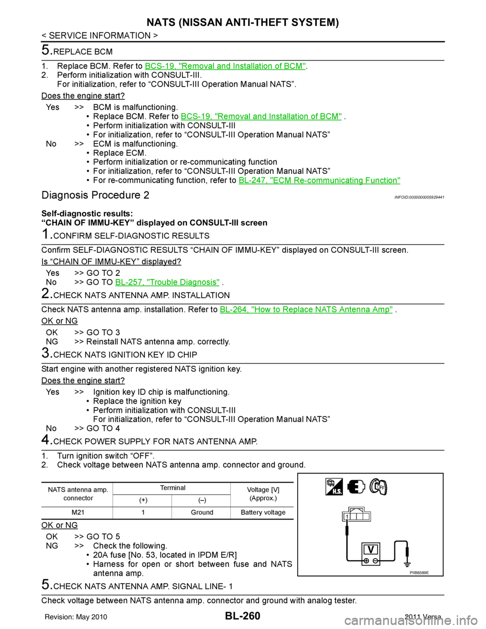
4.CHECK POWER SUPPLY FO R NATS ANTENNA AMP.
1. Turn ignition switch “OFF”.
2. Check voltage between NATS antenna amp. connector and ground.
OK or NG
OK >> GO TO 5
NG >> Check the following. • 20A fuse [No. 53, located in IPDM E/R]
• Harness for open or short between fuse and NATSantenna amp.
5.CHECK NATS ANTENNA AMP. SIGNAL LINE- 1
Check voltage between NATS antenna amp. connector and ground with analog tester.
NATS antenna amp. connector Te r m i n a l
Voltage [V]
(Approx.)
(+) (–)
M21 1Ground Battery voltage
PIIB6589E
Revision: May 2010 2011 Versa
Page 772 of 3787
BL-262
< SERVICE INFORMATION >
NATS (NISSAN ANTI-THEFT SYSTEM)
“ID DISCORD IMM-ECM”:
Registered ID of BCM is in discord with that of ECM.
Is
“ID DISCORD IMM-ECM” displayed?
Ye s > > G O T O 2
No >> GO TO BL-257, "
Trouble Diagnosis" .
2.PERFORM INITIALIZATION WITH CONSULT-III
Perform initialization with CONSULT-III. Re-register all NATS ignition key IDs.
For initialization, refer to “CONSULT-III Operation Manual NATS”.
NOTE:
If the initialization is not completed or ma lfunctions, CONSULT-III shows message on the screen.
Can the system be initialized?
Yes >> • Start engine. (END) • (System initialization had not been completed.)
No >> ECM is malfunctioning. • Replace ECM.
• Perform initialization with CONSULT-III
For initialization, refer to “CONSULT-III Operation Manual NATS”
Diagnosis Procedure 4INFOID:0000000005929443
“COMBINATION METER (SECURITY) DOES NOT LIGHT UP”
1.CHECK FUSE
Check 10A fuse [No.13, located in the fuse block (J/B)]
OK or NG
OK >> GO TO 2
NG >> Replace fuse.
2.CHECK COMBINATION METER (SECURITY)
1. Install 10A fuse.
2. Start engine and turn ignition switch OFF.
3. Check if the combination meter (security) lights up.
OK or NG
OK >> Inspection End.
NG >> GO TO 3
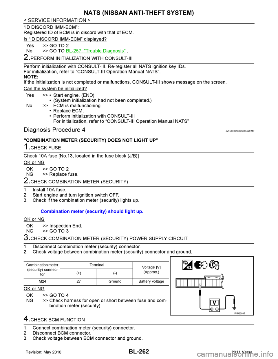
3.CHECK COMBINATION METER (SECURITY) POWER SUPPLY CIRCUIT
1. Disconnect combination meter (security) connector.
2. Check voltage between combination meter (security) connector and ground.
OK or NG
OK >> GO TO 4
NG >> Check harness for open or short between fuse and com- bination meter (security).
4.CHECK BCM FUNCTION
1. Connect combination meter (security) connector.
2. Disconnect BCM connector.
3. Check voltage between BCM connector and ground. Combination meter (security) should light up.
Combination meter
(security) connec-
tor Te r m i n a l
Voltage [V]
(Approx.)
(+) (-)
M24 27Ground Battery voltage
PIIB6593E
Revision: May 2010 2011 Versa
Page 773 of 3787
NATS (NISSAN ANTI-THEFT SYSTEM)BL-263
< SERVICE INFORMATION >
C
DE
F
G H
J
K L
M A
B
BL
N
O P
OK or NG
OK >> BCM is malfunctioning. • Replace BCM. Refer to BCS-19, "
Removal and Instal-
lation of BCM" .
• Perform initialization with CONSULT-III
• For initialization, refer to “CONSULT-III Operation Manual.
NG >> Check the following. • Harness for open or short between combination meter (security) and BCM
• Indicator lamp condition
Diagnosis Procedure 5INFOID:0000000005929444
Self-diagnostic results:
“LOCK MODE” displayed on CONSULT-III screen
1.CONFIRM SELF-DIAGNOSTIC RESULTS
Confirm SELF-DIAGNOSTIC RESULTS “LOCK MODE” is displayed on CONSULT-III screen.
Is
“LOCK MODE” displayed?
Yes >> GO TO 2
No >> GO TO BL-257, "
Trouble Diagnosis" .
2.ESCAPE FROM LOCK MODE
1. Turn ignition switch OFF.
2. Turn ignition switch ON with registered key. (Do not start engine.) Wait 5 seconds.
3. Return the key to OFF position. Wait 5 seconds.
4. Repeat steps 2 and 3 twice (total of three cycles).
5. Start the engine.
Does engine start?
Yes >> System is OK (Now system is escaped from “LOCK MODE”).
No >> GO TO 3
3.PERFORM INITIALIZATION WITH CONSULT-III
Perform initialization with CONSULT-III.
For initialization, refer to “CONSULT-III Operation Manual.
NOTE:
If the initialization is not completed or malf unctions, CONSULT-III shows the message on the screen.
Can the system be initialized?
Yes >> System is OK.
No >> GO TO 4
4.PERFORM INITIALIZATION WITH CONSULT-III AGAIN
1. Replace BCM.
2. Perform initialization with CONSULT-III. For initialization, refer to “CON SULT-III Operation Manual NATS”.
NOTE:
If the initialization is not completed or malf unctions, CONSULT-III shows the message on the screen.
Can the system be initialized?
Yes >> System is OK. (BCM is malfunctioning.)
No >> ECM is malfunctioning. • Replace ECM.
• Perform initialization with CONSULT-III
• For initialization, refer to “CONSULT-III Operation Manual NATS”
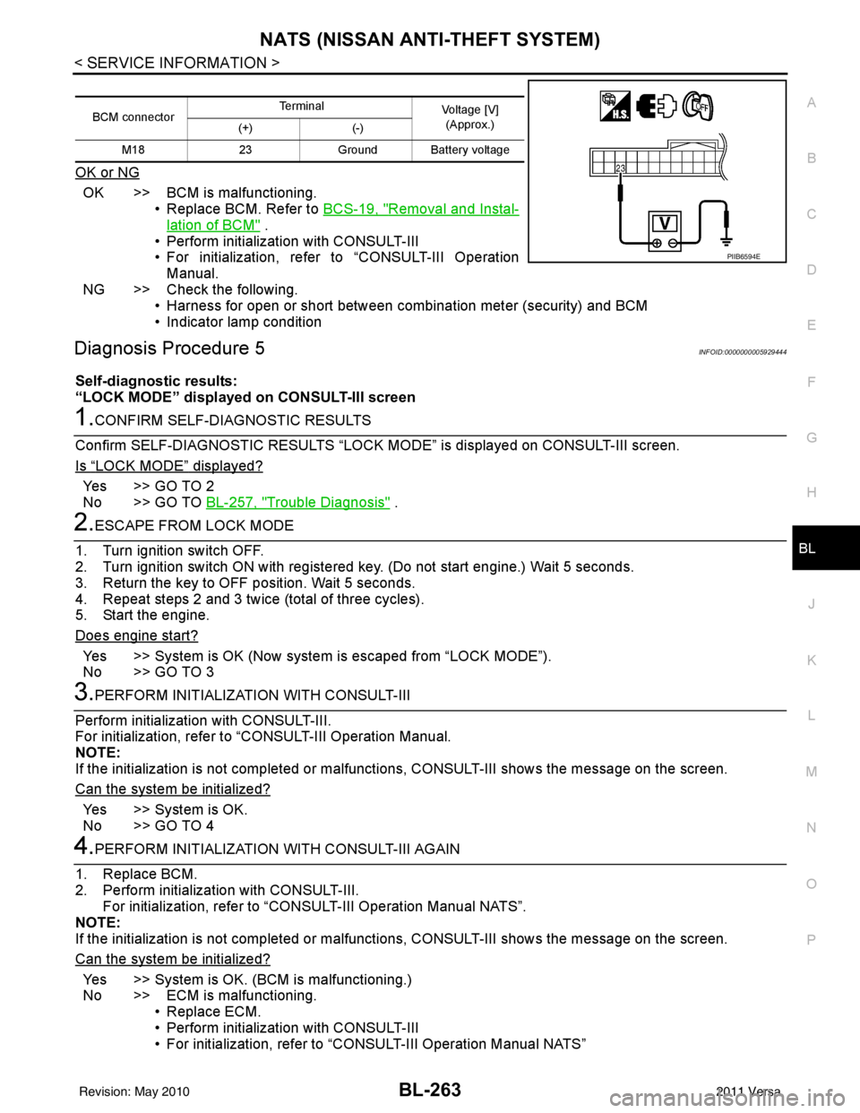
BCM connector Terminal
Voltage [V]
(Approx.)
(+) (-)
M18 23Ground Battery voltage
PIIB6594E
Revision: May 2010 2011 Versa
Page 774 of 3787
BL-264
< SERVICE INFORMATION >
NATS (NISSAN ANTI-THEFT SYSTEM)
Diagnosis Procedure 6
INFOID:0000000005929445
Self-diagnostic results:
“DIFFERENCE OF KEY” disp layed on CONSULT-III screen
1.CONFIRM SELF-DIAGNOSTIC RESULTS
Confirm SELF-DIAGNOSTIC RESU LTS “DIFFERENCE OF KEY” displayed on CONSULT-III screen.
Is
“DIFFERENCE OF KEY” displayed?
YES >> GO TO 2
NO >> GO TO BL-257, "
Trouble Diagnosis".
2.PERFORM INITIALIZATION WITH CONSULT-III
Perform initialization with CONSULT-III. Re-register all NATS ignition key IDs.
For initialization and registration of NATS ignition key IDs, refer to CONSULT-III Operation Manual.
NOTE:
If the initialization is not completed or ma lfunctions, CONSULT-III shows message on the screen.
Can the system be initialized and can the engine be started with re-registered NATS ignition key?
YES >> • Ignition key ID was unregistered.
NO >> • BCM is malfunctioning. • Replace BCM. Refer to BCS-19, "
Removal and Installation of BCM".
• Perform initialization with CONSULT-III.
• For initialization, refer to CONSULT-III Operation Manual.
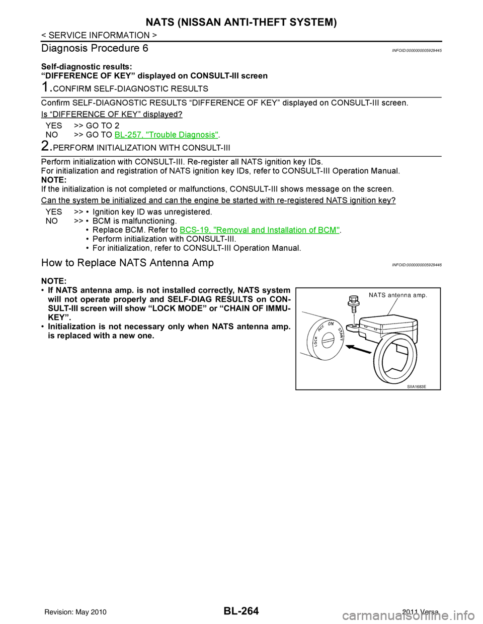
How to Replace NATS Antenna AmpINFOID:0000000005929446
NOTE:
• If NATS antenna amp. is not installed correctly, NATS system
will not operate properly and SELF-DIAG RESULTS on CON-
SULT-III screen will show “LOCK MODE” or “CHAIN OF IMMU-
KEY”.
• Initialization is not necessary only when NATS antenna amp.
is replaced with a new one.
SIIA1683E
Revision: May 2010 2011 Versa
Page 778 of 3787

BL-268
< SERVICE INFORMATION >
BODY REPAIR
4. Front pillar inner reinforcement (RH&LH)
5. Lower dash reinforcement
6. 4th crossmember (RH&LH)
7. Front side member rear extension (RH&LH)
8. 3rd crossmember (RH&LH)
9. Front seat outer rear bracket (RH&LH)
10. Front seat inner rear bracket (RH&LH)
11. 2nd crossmember (RH&LH)
12. Front seat outer front bracket (RH&LH)
13. Front seat inner front bracket (RH&LH)
14. Fender bracket (RH&LH)
15. Strut housing assembly RH
16. Cowl top side upper (RH&LH)
17. Front strut housing (RH&LH)
18. Upper torque rod reinforcement
19. Closing plate assembly RH
20. Engine mount reinforcement
21. Strut tower front reinforcement RH
22. Front hoodledge lower RH
23. Frame bracket outer (RH&LH)
24. Front bumper support bracket (RH&LH)
25. Closing plate (RH&LH)
26. Front suspension rear bracket (RH&LH)
27. Front side member outrigger (RH&LH)
28. Front side member assembly (RH&LH)
29. Front side member (RH&LH)
30. Frame bracket (RH&LH)
31. Closing plate assembly LH
32. Hoodledge connector (RH&LH)
33. Radiator core side support (RH&LH)
34. Radiator core support upper (RH&LH)
35. Hoodledge upper (RH&LH)
36. Hoodledge reinforcement assembly (RH&LH)
37. Dash side (RH&LH)
38. Dash side assembly (RH& LH)
39. Front floor reinforcement (RH&LH)
40. Front floor front (RH&LH)
41. Front floor center
42. Rear seat crossmember
43. Rear center crossmember
44. Rear seat upper crossmember
45. Rear side member (RH&LH)
46. Sill inner extension (RH&LH)
47. Rear side member extension (RH&LH)
48. Rear side member assembly (RH & LH)
49. Rear floor front
50. Rear floor front assembly
51. Rear floor side (RH&LH)
52. Rear floor rear
Revision: May 20102011 Versa
Page 799 of 3787
BODY REPAIRBL-289
< SERVICE INFORMATION >
C
DE
F
G H
J
K L
M A
B
BL
N
O P
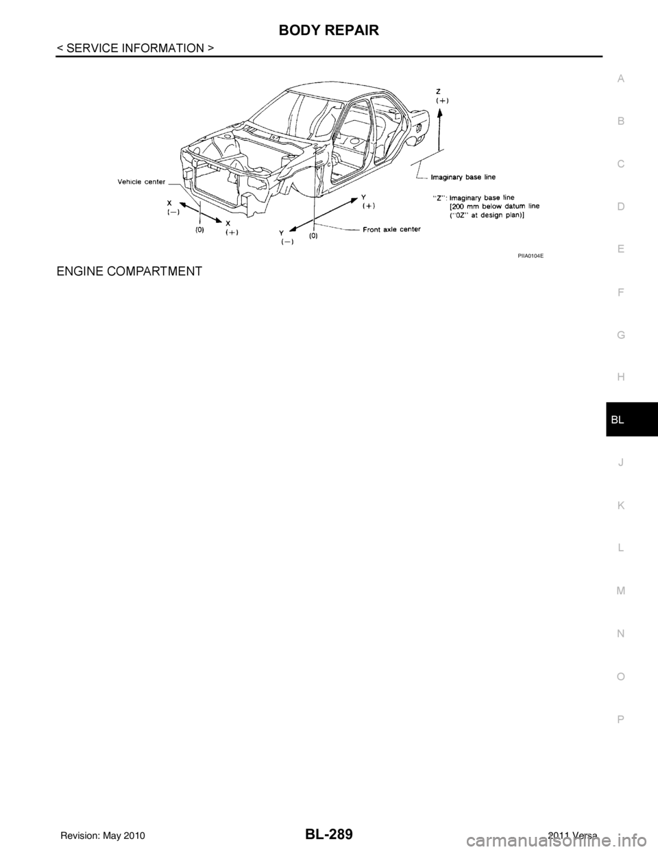
ENGINE COMPARTMENT
PIIA0104E
Revision: May 2010 2011 Versa