2011 NISSAN TIIDA tire type
[x] Cancel search: tire typePage 3214 of 3787
CHASSIS AND BODY MAINTENANCEMA-43
< SERVICE INFORMATION >
C
DE
F
G H
I
J
K
M A
B
MA
N
O P
Do not overfill.
4. Drive vehicle for approximately 5 minutes.
5. Re-check A/T fluid level at A/T fluid temperatures of 50° to 80 °C (122° to 176°F) using “HOT” range on A/
T fluid level gauge.
CAUTION:
• When wiping the A/T fluid level gauge, always use lint-free cloth.
• Firmly fix the A/T fluid level ga uge to the A/T fluid charging pipe using the stopper attached.
6. Check A/T fluid condition and make any necessary repairs. Refer to AT-51, "
Inspections Before Trouble
Diagnosis". If the A/T fluid contains frictional material (clutches, bands, etc.), or if the A/T is repaired, over-
hauled, or replaced, inspect and clean the A/T fluid cooler mounted in the radiator. Refer to AT-18, "
A/T
Fluid Cooler Cleaning".
7. Install the removed A/T fluid level gauge into the A/T fluid charging pipe. CAUTION:
Firmly fix the A/T fluid level gaug e to the A/T fluid charging pipe using the stopper attached.
A/T FLUID : Changing A/T FluidINFOID:0000000005931176
1. Warm up A/T fluid.
2. Stop engine.
3. Drain A/T fluid by removing the drain plug. Re install the drain plug to the specified torque.
CAUTION:
Do not reuse drain plug gasket.
4. Refill the transaxle with new specified A/T fluid through the A/T fluid charging pipe. Always refill the tran- saxle with the same volume of A/T fluid that was drained out.
5. Run engine at idle speed for 5 minutes.
6. Check A/T fluid level and condition. Refer to MA-42, "
A/T FLUID : Checking A/T Fluid".
WHEELS
WHEELS : AdjustmentINFOID:0000000006413331
BALANCING WHEELS (ADHESIVE WEIGHT TYPE)
Preparation Before Adjustment
Remove inner and outer balance weights from the r oad wheel using releasing agent, remove double-faced
adhesive tape from the road wheel.
CAUTION:
• Be careful not scratch the road wheel during removal.
• After removing double-faced adhesive tape, wipe clean traces of releasing agent from the road
wheel.
Wheel Balance Adjustment
• If a balancer machine has an adhesive weight mode setting, select the adhesive weight mode setting and skip Step 2. below. If a balancer machine only has the clip-on (rim flange) weight mode setting, follow Step 2.
to calculate the correct size adhesive weight.
1. Set road wheel on balancer machine using the cent er hole as a guide. Start the balancer machine.
2. For tire balance machines that only have a clip-on (ri m flange) weight mode setting, follow this step to cal-
culate the correct size adhesive weight to use. When inner and outer imbalance values are shown on the
balancer machine indicator, multiply outer imbalance value by 5/3 (1.67) to determine balance weight that
should be used. Select the outer balance weight with a value closest to the calculated value above and
install in to the designated outer position of, or at the designated angle in relation to the road wheel.
Drain plug: Refer to
AT-237, "
Component".
Fluid grade and capacity: Refer to MA-14
.
Revision: May 2010 2011 Versa
Page 3216 of 3787

CHASSIS AND BODY MAINTENANCEMA-45
< SERVICE INFORMATION >
C
DE
F
G H
I
J
K
M A
B
MA
N
O P
• Follow the maintenance schedule for tire rotation service intervals. Refer to MA-7, "
General Maintenance".
• When installing the wheel, tighten wheel nuts to the specified
torque.
CAUTION:
• Do not include the T-type spare tire when rotating the tires.
• When installing wheels, tighte n them diagonally by dividing
the work two to three times in order to prevent the wheels
from developing any distortion.
• Be careful not to tighten wh eel nut at torque exceeding the
criteria for preventing strain of disc rotor.
• Use NISSAN genuine wheel nuts for aluminum wheels.
• Perform the ID registration, after tire rotation. Refer to WT-13, "
ID Registration Procedure".
BRAKE FLUID LEVEL AND LEAKS
BRAKE FLUID LEVEL AND LEAKS : On Board InspectionINFOID:0000000005931179
CHECKING BRAKE FLUID LEVEL
• Make sure the fluid level in the reservoir tank is within the standard
(between MAX and MIN lines).
• Visually check around the reservoir tank for fluid leaks.
• If fluid level is excessively low, check brake system for fluid leaks.
• Release parking brake lever and see if brake warning lamp goes off. If not, check brake system for fluid leaks.
BRAKE FLUID LEVEL AND LEAKS : Drain and RefillINFOID:0000000005931180
CAUTION:
• Refill using recommended brake fluid. Refer to MA-14, "
Fluids and Lubricants".
• Never reuse drained brake fluid.
• Be careful not to splash brake fluid on painted areas; it may cause paint damage. If brake fluid is
splashed on painted areas, immediately wipe th em with cloth and wash it away with water.
• Before working, disconnect connect ors of ABS actuator and electric unit (control unit) or battery
negative terminal.
1. Connect a vinyl tube to bleed valve.
2. Depress the brake pedal, loosen the bleed valve, and gradually remove the brake fluid.Wheel nut tightening
torque
: 113 N·m (12 kg-m, 83 ft-lb)
SMA829C
SFIA3067E
WFIA0512E
Revision: May 2010
2011 Versa
Page 3397 of 3787
REFRIGERANT LINESMTC-81
< SERVICE INFORMATION >
C
DE
F
G H
I
K L
M A
B
MTC
N
O P
INSPECTION FOR CLUTCH DISC TO PULLEY CLEARANCE
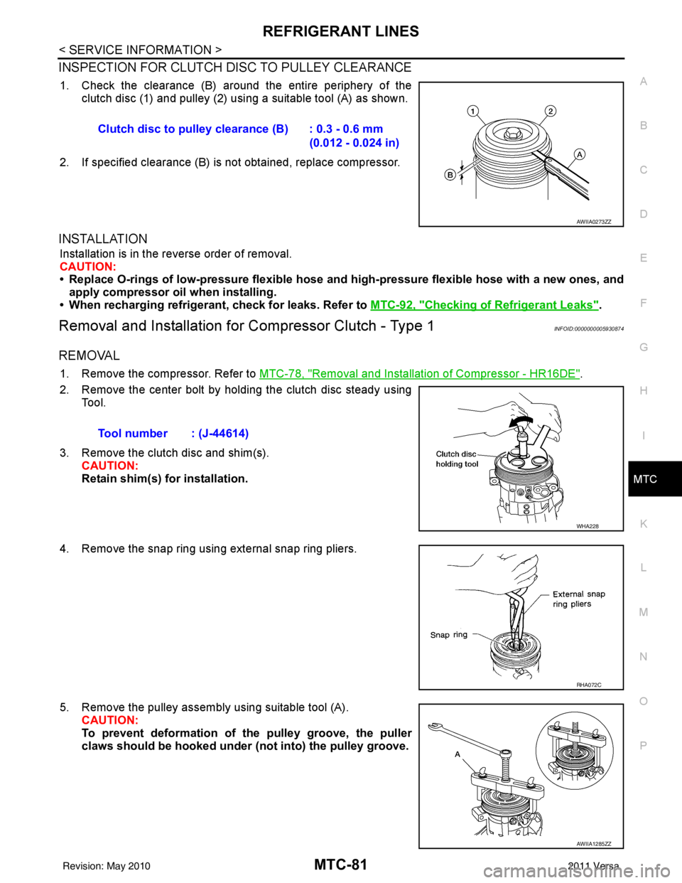
1. Check the clearance (B) around the entire periphery of the clutch disc (1) and pulley (2) usi ng a suitable tool (A) as shown.
2. If specified clearance (B) is not obtained, replace compressor.
INSTALLATION
Installation is in the reverse order of removal.
CAUTION:
• Replace O-rings of low-pressure flexible hose and high-pressure flexible hose with a new ones, and
apply compressor oil when installing.
• When recharging refrigerant, check for leaks. Refer to MTC-92, "
Checking of Refrigerant Leaks".
Removal and Installation for Compressor Clutch - Type 1INFOID:0000000005930874
REMOVAL
1. Remove the compressor. Refer to MTC-78, "Removal and Installation of Compressor - HR16DE".
2. Remove the center bolt by holding the clutch disc steady using Tool.
3. Remove the clutch disc and shim(s). CAUTION:
Retain shim(s) for installation.
4. Remove the snap ring using external snap ring pliers.
5. Remove the pulley assembly using suitable tool (A). CAUTION:
To prevent deformation of the pulley groove, the puller
claws should be hooked under (not into) the pulley groove.
Clutch disc to pulley clearance (B) : 0.3 - 0.6 mm
(0.012 - 0.024 in)
AWIIA0273ZZ
Tool number : (J-44614)
WHA228
RHA072C
AWIIA1285ZZ
Revision: May 2010 2011 Versa
Page 3399 of 3787
REFRIGERANT LINESMTC-83
< SERVICE INFORMATION >
C
DE
F
G H
I
K L
M A
B
MTC
N
O P
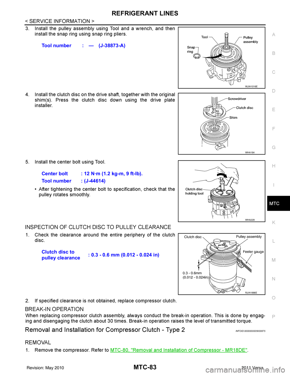
3. Install the pulley assembly using Tool and a wrench, and then install the snap ring using snap ring pliers.
4. Install the clutch disc on the drive shaft, together with the original shim(s). Press the clutch disc down using the drive plate
installer.
5. Install the center bolt using Tool. • After tightening the center bolt to specification, check that thepulley rotates smoothly.
INSPECTION OF CLUTCH DISC TO PULLEY CLEARANCE
1. Check the clearance around the entire periphery of the clutch
disc.
2. If specified clearance is not obt ained, replace compressor clutch.
BREAK-IN OPERATION
When replacing compressor clutch assembly, always conduct the break-in operation. This is done by engag-
ing and disengaging the clutch about 30 times. Break-in operation raises the level of transmitted torque.
Removal and Installation for Compressor Clutch - Type 2INFOID:0000000005930875
REMOVAL
1. Remove the compressor. Refer to MTC-80, "Removal and Installation of Compressor - MR18DE".
Tool number : — (J-38873-A)
WJIA1016E
WHA184
Center bolt : 12 N·m (1.2 kg-m, 9 ft-lb).
Tool number : (J-44614)
WHA229
Clutch disc to
pulley clearance
: 0.3 - 0.6 mm (0.012 - 0.024 in)
RJIA1886E
Revision: May 2010
2011 Versa
Page 3402 of 3787
MTC-86
< SERVICE INFORMATION >
REFRIGERANT LINES
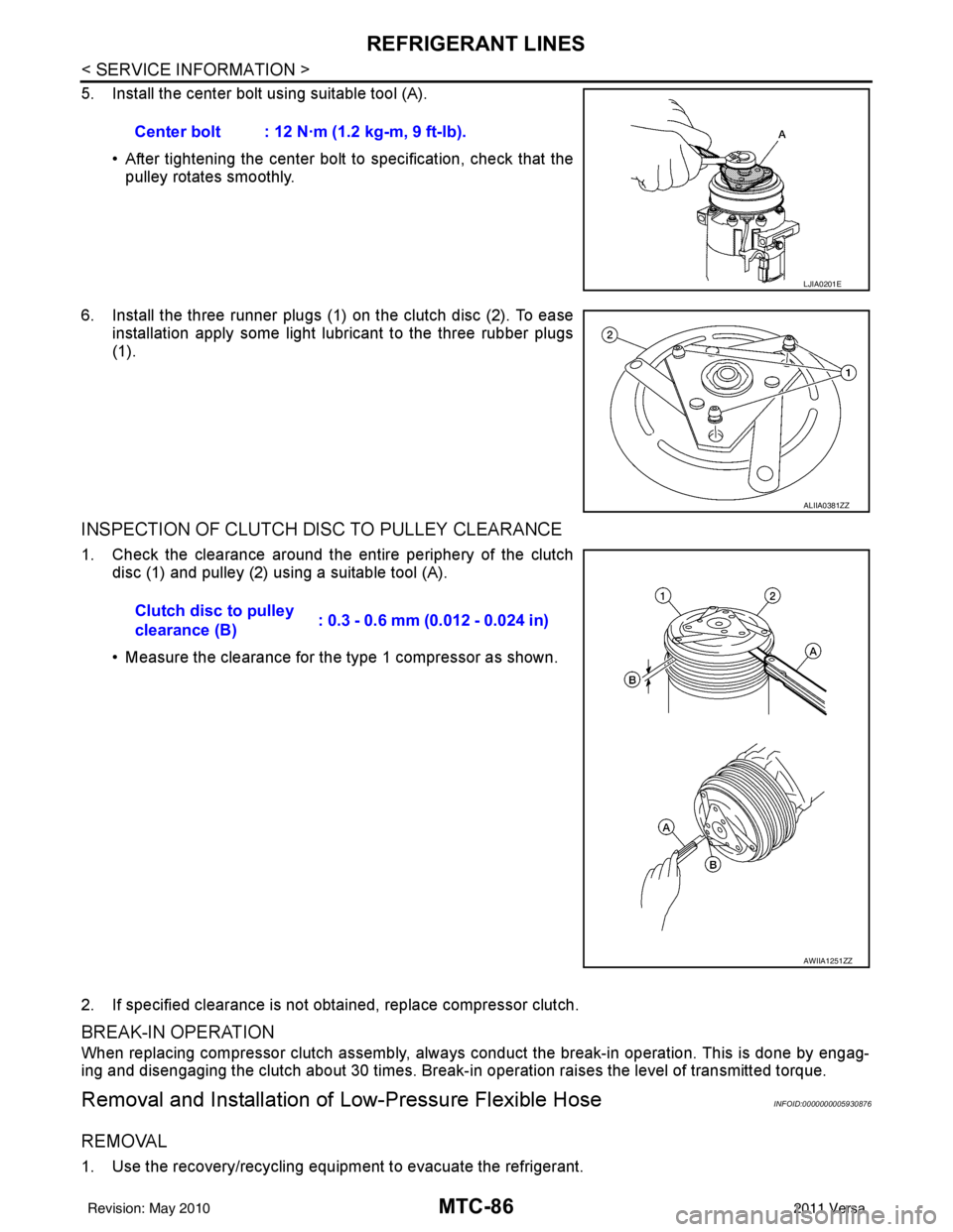
5. Install the center bolt using suitable tool (A).• After tightening the center bolt to specification, check that the
pulley rotates smoothly.
6. Install the three runner plugs (1) on the clutch disc (2). To ease installation apply some light lubricant to the three rubber plugs
(1).
INSPECTION OF CLUTCH DISC TO PULLEY CLEARANCE
1. Check the clearance around the entire periphery of the clutchdisc (1) and pulley (2) using a suitable tool (A).
• Measure the clearance for the type 1 compressor as shown.
2. If specified clearance is not obtained, replace compressor clutch.
BREAK-IN OPERATION
When replacing compressor clutch assembly, always conduct the break-in operation. This is done by engag-
ing and disengaging the clutch about 30 times. Break-in operation raises the level of transmitted torque.
Removal and Installation of Low-Pressure Flexible HoseINFOID:0000000005930876
REMOVAL
1. Use the recovery/recycling equipment to evacuate the refrigerant.Center bolt : 12 N·m (1.2 kg-m, 9 ft-lb).
LJIA0201E
ALIIA0381ZZ
Clutch disc to pulley
clearance (B)
: 0.3 - 0.6 mm (0.012 - 0.024 in)
AWIIA1251ZZ
Revision: May 2010
2011 Versa
Page 3509 of 3787
POWER STEERING GEARPS-15
< SERVICE INFORMATION >
C
DE
F
H I
J
K L
M A
B
PS
N
O P
POWER STEERING GEAR
Removal and InstallationINFOID:0000000005929636
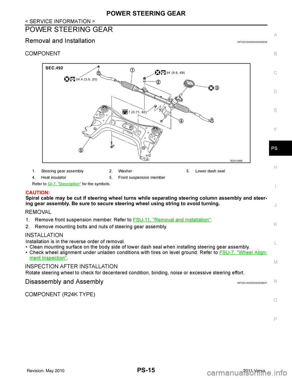
COMPONENT
CAUTION:
Spiral cable may be cut if steering wheel turns while separating steering column assembly and steer-
ing gear assembly. Be sure to secure steering wheel using stri ng to avoid turning.
REMOVAL
1. Remove front suspension member. Refer to FSU-11, "Removal and Installation".
2. Remove mounting bolts and nuts of steering gear assembly.
INSTALLATION
Installation is in the reverse order of removal.
• Clean mounting surface on the body side of lower dash seal when installing steering gear assembly.
• Check wheel alignment under unladen conditions with tires on level ground. Refer to FSU-7, "
Wheel Align-
ment Inspection".
INSPECTION AFTER INSTALLATION
Rotate steering wheel to check for decentered condition, binding, noise or excessive steering effort.
Disassembly and AssemblyINFOID:0000000005929637
COMPONENT (R24K TYPE)
1. Steering gear assembly2. Washer 3. Lower dash seal
4. Heat insulator 5. Front suspension member
Refer to GI-7, "
Description" for the symbols.
SGIA1296E
Revision: May 2010 2011 Versa
Page 3559 of 3787
RSU-6
< SERVICE INFORMATION >
REAR SUSPENSION ASSEMBLY
REAR SUSPENSION ASSEMBLY
On-Vehicle Inspection and ServiceINFOID:0000000005931084
Make sure the mounting conditions (looseness, backlash) of each component and component conditions
(wear, damage) are within specifications.
SHOCK ABSORBER INSPECTION
Check shock absorber for oil leakage, damage and replace it if necessary.
Wheel AlignmentInspectionINFOID:0000000005931085
DESCRIPTION
Measure wheel alignment under unladen conditions.
NOTE:
“Unladen conditions” means that fuel, engine coolant, and lubricant are full. Spare tire, jack, hand tools and
mats are in designated positions.
PRELIMINARY
Check the following:
1. Tires for improper air pressure and wear.
2. Road wheels for runout. Refer to WT-6
.
3. Wheel bearing axial end play. Refer to RAX-6, "
On-Vehicle Inspection and Service" .
4. Shock absorber operation.
5. Each mounting part of suspension for looseness and deformation.
6. Rear suspension beam for cracks, deformation, and other damage.
7. Vehicle height (posture).
GENERAL INFORMATION AND RECOMMENDATIONS
1. A Four-Wheel Thrust Alignment should be performed. • This type of alignment is recommended for any NISSAN vehicle.
• The four-wheel “thrust” process helps ensure that the vehicle is properly aligned and the steering wheel
is centered.
• The alignment machine itself should be ca pable of accepting any NISSAN vehicle.
• The alignment machine should be checked to ensure that it is level.
2. Make sure the alignment machine is properly calibrated. • Your alignment machine should be regularly calibrated in order to give correct information.
• Check with the manufacturer of your specific al ignment machine for their recommended Service/Cali-
bration Schedule.
THE ALIGNMENT PROCESS
IMPORTANT: Use only the alignment specifications listed in this Service Manual. Refer to RSU-13, "Wheel
Alignment (Unladen*)" .
1. When displaying the alignment settings, many alignment machines use “indicators”: (Green/red, plus or minus, Go/No Go). Do NOT use these indicators.
• The alignment specifications programmed into your alignment machine that operate these indicators may not be correct.
• This may result in an ERROR.
2. Some newer alignment machines are equipped with an optional “Rolling Compensation” method to “com- pensate” the sensors (alignment targets or head units). Do NOT use this “Rolling Compensation”
method.
• Use the “Jacking Compensation” method. After inst alling the alignment targets or head units, raise the
vehicle and rotate the wheels 1/2 turn both ways.
• See Instructions in the alignment machine you are using for more information.
CAMBER INSPECTION
Revision: May 2010 2011 Versa
Page 3636 of 3787

SRS-2
< PRECAUTION >
PRECAUTIONS
PRECAUTION
PRECAUTIONS
Precaution for Supplemental Restraint System (SRS) "AIR BAG" and "SEAT BELT
PRE-TENSIONER"
INFOID:0000000006211104
The Supplemental Restraint System such as “A IR BAG” and “SEAT BELT PRE-TENSIONER”, used along
with a front seat belt, helps to reduce the risk or severity of injury to the driver and front passenger for certain
types of collision. This system includes seat belt switch inputs and dual stage front air bag modules. The SRS
system uses the seat belt switches to determine the front air bag deployment, and may only deploy one front
air bag, depending on the severity of a collision and w hether the front occupants are belted or unbelted.
Information necessary to service the system safely is included in the SRS and SB section of this Service Man-
ual.
WARNING:
• To avoid rendering the SRS inopera tive, which could increase the risk of personal injury or death in
the event of a collision which would result in air bag inflation, all maintenance must be performed by
an authorized NISSAN/INFINITI dealer.
• Improper maintenance, including in correct removal and installation of the SRS, can lead to personal
injury caused by unintent ional activation of the system. For re moval of Spiral Cable and Air Bag
Module, see the SRS section.
• Do not use electrical test equipmen t on any circuit related to the SRS unless instructed to in this
Service Manual. SRS wiring harn esses can be identified by yellow and/or orange harnesses or har-
ness connectors.
PRECAUTIONS WHEN USING POWER TOOLS (AIR OR ELECTRIC) AND HAMMERS
WARNING:
• When working near the Airbag Diagnosis Sensor Unit or other Airbag System sensors with the Igni-
tion ON or engine running, DO NOT use air or electri c power tools or strike near the sensor(s) with a
hammer. Heavy vibration could activate the sensor( s) and deploy the air bag(s), possibly causing
serious injury.
• When using air or electric power tools or hammers , always switch the Ignition OFF, disconnect the
battery, and wait at least 3 minu tes before performing any service.
Precaution for SRS "AIR BAG" and "S EAT BELT PRE-TENSIONER" Service
INFOID:0000000006211105
• Do not use electrical test equipment to check SRS ci rcuits unless instructed to in this Service Manual.
• Before servicing the SRS, turn ignition switch OFF, disconnect both battery cables and wait at least 3 min- utes.
For approximately 3 minutes after the cables are removed, it is still possible for the air bag and seat belt pre-
tensioner to deploy. Therefore, do not work on any SR S connectors or wires until at least 3 minutes have
passed.
• The air bag diagnosis sensor unit must always be installed with the arrow mark “ ⇐” pointing toward the front
of the vehicle for proper operation. Also check air bag diagnosis sensor unit for cracks, deformities or rust
before installation and replace as required.
• The spiral cable must be aligned with the neutral position since its rotations are limited. Do not attempt to
turn steering wheel or column after removal of steering gear.
• Handle air bag module carefully. Always place driver and front passenger air bag modules with the pad side facing upward and seat mounted front side air bag module standing with the stud bolt side facing down.
• Conduct self-diagnosis to check entire SRS for proper function after replacing any components.
• After air bag inflates, the front instrument panel assembly should be replaced if damaged.
• Do not reuse center pillar upper garnish if removed.
Precaution Necessary for Steering W heel Rotation After Battery Disconnect
INFOID:0000000006211106
NOTE:
• This Procedure is applied only to models with Intelligent Key system and NATS (NISSAN ANTI-THEFT SYS-
TEM).
• Remove and install all control units after disconnecting both battery cables with the ignition knob in the
″LOCK ″ position.
Revision: May 2010 2011 Versa