2011 NISSAN TIIDA tire pressure
[x] Cancel search: tire pressurePage 712 of 3787
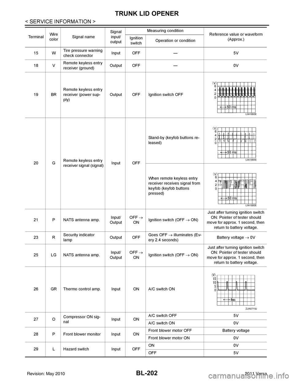
BL-202
< SERVICE INFORMATION >
TRUNK LID OPENER
15 WTire pressure warning
check connector
Input OFF
—5V
18 V Remote keyless entry
receiver (ground) Output OFF
—0V
19 BR Remote keyless entry
receiver (power sup-
ply) Output OFF Ignition switch OFF
20 G Remote keyless entry
receiver signal (signal)
Input OFFStand-by (keyfob buttons re-
leased)
When remote keyless entry
receiver receives signal from
keyfob (keyfob buttons
pressed)
21 P NATS antenna amp. Input/
Output OFF
→
ON Ignition switch (OFF
→ ON)Just after turning ignition switch
ON: Pointer of tester should
move for approx. 1 second, then
return to battery voltage.
23 R Security indicator
lamp Output OFF
Goes OFF
→ illuminates (Ev-
ery 2.4 seconds) Battery voltage
→ 0V
25 LG NATS antenna amp. Input/
Output OFF
→
ON Ignition switch (OFF
→ ON)Just after turning ignition switch
ON: Pointer of tester should
move for approx. 1 second, then return to battery voltage.
26 GR Thermo control amp. Input ON A/C switch ON
27 O Compressor ON sig-
nal Input ONA/C switch OFF
5V
A/C switch ON 0V
28 P Front blower monitor Input ON Front blower motor OFF
Battery voltage
Front blower motor ON 0V
29 L Hazard switch Input OFFON
0V
OFF 5V
Te r m i n a l
Wire
color Signal name Signal
input/
output Measuring condition
Reference value or waveform
(Approx.)
Ignition
switch Operation or condition
LIIA1893E
LIIA1894E
LIIA1895E
ZJIA0719J
Revision: May 2010
2011 Versa
Page 737 of 3787
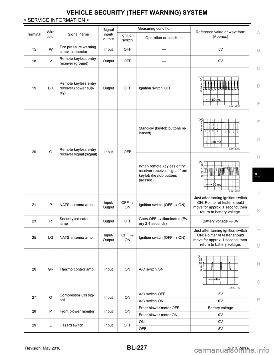
VEHICLE SECURITY (THEFT WARNING) SYSTEMBL-227
< SERVICE INFORMATION >
C
DE
F
G H
J
K L
M A
B
BL
N
O P
15 W Tire pressure warning
check connector
Input OFF
—5V
18 V Remote keyless entry
receiver (ground) Output OFF
—0V
19 BR Remote keyless entry
receiver (power sup-
ply) Output OFF Ignition switch OFF
20 G Remote keyless entry
receiver signal (signal)
Input OFFStand-by (keyfob buttons re-
leased)
When remote keyless entry
receiver receives signal from
keyfob (keyfob buttons
pressed)
21 P NATS antenna amp. Input/
Output OFF
→
ON Ignition switch (OFF → ON) Just after turning ignition switch
ON: Pointer of tester should
move for approx. 1 second, then
return to battery voltage.
23 R Security indicator
lamp Output OFF
Goes OFF
→ illuminates (Ev-
ery 2.4 seconds) Battery voltage
→ 0V
25 LG NATS antenna amp. Input/
Output OFF
→
ON Ignition switch (OFF → ON) Just after turning ignition switch
ON: Pointer of tester should
move for approx. 1 second, then return to battery voltage.
26 GR Thermo control amp. Input ON A/C switch ON
27 O Compressor ON sig-
nal Input ONA/C switch OFF
5V
A/C switch ON 0V
28 P Front blower monitor Input ON Front blower motor OFF
Battery voltage
Front blower motor ON 0V
29 L Hazard switch Input OFFON
0V
OFF 5V
Te r m i n a l
Wire
color Signal name Signal
input/
output Measuring condition
Reference value or waveform
(Approx.)
Ignition
switch Operation or condition
LIIA1893E
LIIA1894E
LIIA1895E
ZJIA0719J
Revision: May 2010
2011 Versa
Page 761 of 3787
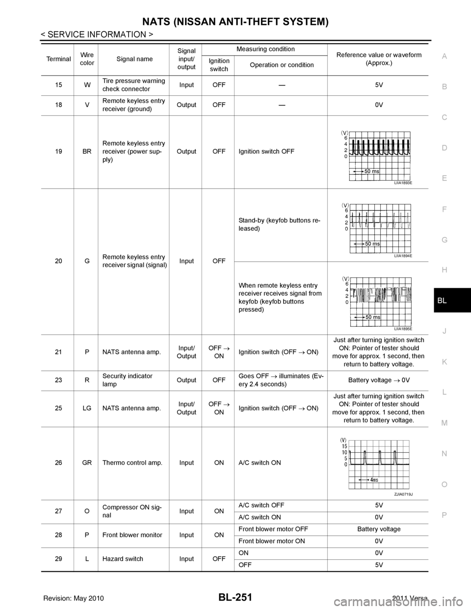
NATS (NISSAN ANTI-THEFT SYSTEM)BL-251
< SERVICE INFORMATION >
C
DE
F
G H
J
K L
M A
B
BL
N
O P
15 W Tire pressure warning
check connector
Input OFF
—5V
18 V Remote keyless entry
receiver (ground) Output OFF
—0V
19 BR Remote keyless entry
receiver (power sup-
ply) Output OFF Ignition switch OFF
20 G Remote keyless entry
receiver signal (signal)
Input OFFStand-by (keyfob buttons re-
leased)
When remote keyless entry
receiver receives signal from
keyfob (keyfob buttons
pressed)
21 P NATS antenna amp. Input/
Output OFF
→
ON Ignition switch (OFF → ON) Just after turning ignition switch
ON: Pointer of tester should
move for approx. 1 second, then
return to battery voltage.
23 R Security indicator
lamp Output OFF
Goes OFF
→ illuminates (Ev-
ery 2.4 seconds) Battery voltage
→ 0V
25 LG NATS antenna amp. Input/
Output OFF
→
ON Ignition switch (OFF → ON) Just after turning ignition switch
ON: Pointer of tester should
move for approx. 1 second, then return to battery voltage.
26 GR Thermo control amp. Input ON A/C switch ON
27 O Compressor ON sig-
nal Input ONA/C switch OFF
5V
A/C switch ON 0V
28 P Front blower monitor Input ON Front blower motor OFF
Battery voltage
Front blower motor ON 0V
29 L Hazard switch Input OFFON
0V
OFF 5V
Te r m i n a l
Wire
color Signal name Signal
input/
output Measuring condition
Reference value or waveform
(Approx.)
Ignition
switch Operation or condition
LIIA1893E
LIIA1894E
LIIA1895E
ZJIA0719J
Revision: May 2010
2011 Versa
Page 908 of 3787
![NISSAN TIIDA 2011 Service Repair Manual TROUBLE DIAGNOSISBRC-19
< SERVICE INFORMATION > [ABS]
C
D
E
G H
I
J
K L
M A
B
BRC
N
O P
Note 1: Confirm tire pressure is normal.
Note 2: ON/OFF timing of ABS warning lamp
ON: For approximately 2 secon](/manual-img/5/57396/w960_57396-907.png "NISSAN TIIDA 2011 Service Repair Manual TROUBLE DIAGNOSISBRC-19
< SERVICE INFORMATION > [ABS]
C
D
E
G H
I
J
K L
M A
B
BRC
N
O P
Note 1: Confirm tire pressure is normal.
Note 2: ON/OFF timing of ABS warning lamp
ON: For approximately 2 secon")
TROUBLE DIAGNOSISBRC-19
< SERVICE INFORMATION > [ABS]
C
D
E
G H
I
J
K L
M A
B
BRC
N
O P
Note 1: Confirm tire pressure is normal.
Note 2: ON/OFF timing of ABS warning lamp
ON: For approximately 2 seconds after ignition switch is turned ON, or when a malfunction is detected.
OFF: Approximately 2 seconds after ignition switch is turned ON (when system is in normal operation).
CONSULT-III Function (ABS)INFOID:0000000005928445
CONSULT-III can display each diagnostic item using the diagnostic test modes shown following.
Monitor item Display content Data monitor
Note: Error inspection
checklist
Condition Reference value in
normal operation
FR RH SENSOR
FR LH SENSOR
RR RH SENSOR
RR LH SENSOR Wheel speedVehicle stopped
0 [km/h (MPH)]
BRC-25, "
Wheel Sensor
System"Vehicle running (Note 1) Almost in accor-
dance with speed-
ometer display
(within
±10%)
BATTERY VOLT Battery voltage sup-
plied to ABS actuator
and electric unit (con-
trol unit)Ignition switch ON
10 to 16VBRC-28, "
ABS Control
Unit Power and Ground
Systems Inspection"
STOP LAMP SW
Stop lamp switch oper-
ationBrake pedal depressed ON
—
Brake pedal not depressed OFF
ABS WARN LAMP ABS warning lamp ON
condition (Note 2)ABS warning lamp ON ON
BRC-17, "
Basic Inspec-
tion"ABS warning lamp OFF OFF
MOTOR RELAY Operation status of mo-
tor and motor relayIgnition switch ON or running
(ABS not activated)
OFF
BRC-27, "
Actuator Motor,
Motor Relay, and Circuit
Inspection"Ignition switch ON or engine
running (ABS activated) ON
ACTUATOR RLY Actuator relay opera-
tion statusVehicle stopped (Ignition
switch ON)
OFF
BRC-27, "
Actuator Motor,
Motor Relay, and Circuit
Inspection"Vehicle stopped (Engine run-
ning) ON
FR LH IN SOL
FR LH OUT SOL
FR RH IN SOL
FR RH OUT SOL
RR RH IN SOL
RR RH OUT SOL
RR LH IN SOL
RR LH OUT SOL Solenoid valve opera-
tionActuator (solenoid) is active
(“ACTIVE TEST” with CON-
SULT-III) or actuator relay is in-
active (in fail-safe mode).
ON
BRC-26, "
Solenoid Valve
System Inspection"When actuator (solenoid) is not
active and actuator relay is ac-
tive (ignition switch ON). OFF
ABS SIGNAL
EBD SIGNAL Signal statusABS active
EBD active
ON
ABS system
EBD system
ABS not active
EBD not active OFF
ABS FAIL SIG
EBD FAIL SIG Fail signal statusABS fail
EBD fail
ON
ABS system
EBD system
ABS normal
EBD normal OFF
Diagnostic mode
Description
SELF DIAGNOSTIC RESULT Displays ABS actuator and electric unit (control unit) self-diagnosis results. DATA MONITOR Displays ABS actuator and electric unit (control unit) input/output data in real time.
CAN DIAG SUPPORT MNTR The result of transmit/receive diagnosis of CAN communication can be read. ACTIVE TEST Operation of electrical loads can be checked by sending drive signal to them.
Revision: May 2010 2011 Versa
Page 914 of 3787
![NISSAN TIIDA 2011 Service Repair Manual TROUBLE DIAGNOSIS FOR SELF-DIAGNOSTIC ITEMS
BRC-25
< SERVICE INFORMATION > [ABS]
C
D
E
G H
I
J
K L
M A
B
BRC
N
O P
TROUBLE DIAGNOSIS FOR SELF-DIAGNOSTIC ITEMS
Wheel Sensor SystemINFOID:00000000059284](/manual-img/5/57396/w960_57396-913.png "NISSAN TIIDA 2011 Service Repair Manual TROUBLE DIAGNOSIS FOR SELF-DIAGNOSTIC ITEMS
BRC-25
< SERVICE INFORMATION > [ABS]
C
D
E
G H
I
J
K L
M A
B
BRC
N
O P
TROUBLE DIAGNOSIS FOR SELF-DIAGNOSTIC ITEMS
Wheel Sensor SystemINFOID:00000000059284")
TROUBLE DIAGNOSIS FOR SELF-DIAGNOSTIC ITEMS
BRC-25
< SERVICE INFORMATION > [ABS]
C
D
E
G H
I
J
K L
M A
B
BRC
N
O P
TROUBLE DIAGNOSIS FOR SELF-DIAGNOSTIC ITEMS
Wheel Sensor SystemINFOID:0000000005928446
INSPECTION PROCEDURE
1.CONNECTOR INSPECTION
Disconnect the ABS actuator and electric unit (control unit) connector E33 and wheel sensor of malfunctioning
code.
Check the terminals for deformation, disconnection, looseness or damage.
OK or NG
OK >> GO TO 2.
NG >> Repair or replace as necessary.
2.CHECK WHEEL SENSOR OUTPUT SIGNAL
1. Connect ABS active wheel sensor tester (J- 45741) to wheel sensor using appropriate adapter.
2. Turn on the ABS active wheel sensor tester power switch.
NOTE:
The green POWER indicator should illuminate. If the POWER indicator does not illuminate, replace the
battery in the ABS active wheel sensor tester before proceeding.
3. Spin the wheel of the vehicle by hand and observe the red SENSOR indicator on the ABS active wheel
sensor tester. The red SENSOR indicator should flash on and off to indicate an output signal.
NOTE:
If the red SENSOR indicator illuminates but does not flash, reverse the polarity of the tester leads and
retest.
Does the ABS active wheel s ensor tester detect a signal?
YES >> GO TO 3.
NO >> Replace the wheel sensor. Refer to BRC-33, "
Removal and Installation".
3.CHECK TIRES
Check for inflation pressure, wear and size of each tire. Refer to WT-28
.
Are tire pressure and size correct and is tire wear within specifications?
YES >> GO TO 4.
NO >> Adjust tire pressure or replace tire(s).
4.CHECK WHEEL BEARINGS
Check wheel bearing axial end play. Refer to FA X - 6 , "
On-Vehicle Inspection and Service" or RAX-6, "On-Vehi-
cle Inspection and Service".
OK or NG
OK >> GO TO 5.
NG >> Repair or replace as necessary. Refer to FA X - 6 , "
Removal and Installation" or RAX-6, "Removal
and Installation".
5.CHECK WIRING HARNESS FOR SHORT CIRCUIT
1. Turn ignition switch OFF.
2. Disconnect ABS actuator and electric unit (control unit) connec- tor and wheel sensor connector of malfunction code No.
3. Check continuity between wheel sensor harness connector ter- minals and ground.
OK or NG
OK >> GO TO 6.
NG >> Repair the circuit.
6.CHECK WIRING HARNESS FOR OPEN CIRCUIT Continuity should not exist.
WFIA0498E
Revision: May 2010
2011 Versa
Page 949 of 3787
![NISSAN TIIDA 2011 Service Repair Manual BRC-60
< SERVICE INFORMATION >[VDC/TCS/ABS]
TROUBLE DIAGNOSIS
Note 1: Confirm tire pressure is normal.
Note 2: On and Off timing for warning lamp and indicator lamp.
CONSULT-III Function (ABS)INFOID:0](/manual-img/5/57396/w960_57396-948.png "NISSAN TIIDA 2011 Service Repair Manual BRC-60
< SERVICE INFORMATION >[VDC/TCS/ABS]
TROUBLE DIAGNOSIS
Note 1: Confirm tire pressure is normal.
Note 2: On and Off timing for warning lamp and indicator lamp.
CONSULT-III Function (ABS)INFOID:0")
BRC-60
< SERVICE INFORMATION >[VDC/TCS/ABS]
TROUBLE DIAGNOSIS
Note 1: Confirm tire pressure is normal.
Note 2: On and Off timing for warning lamp and indicator lamp.
CONSULT-III Function (ABS)INFOID:0000000005928483
CONSULT-III can display each diagnostic item us
ing the diagnostic test modes shown following.
SELF-DIAGNOSIS
Description
If an error is detected in the system, the ABS warning lamp will turn on. In this case, perform self-diagnosis as
follows:
Operation Procedure
1. Turn ignition switch OFF.
2. Connect CONSULT-III To the data link connector.
3. Turn ignition switch ON.
4. Start engine and drive at approximately 30 km/h (19 MPH) for approximately 1 minute.
5. After stopping the vehicle, with the engine running, t ouch “ABS”, “SELF-DIAG RESULTS” in order on the
CONSULT-III screen.
USV[FL-RR]
USV[FR-RL]
HSV[FL-RR]
HSV[FR-RL] VDC switch-over valve
statusWhen actuator (switch-over
valve) is active (“ACTIVE
TEST” with CONSULT-III) or
actuator relay is inactive (when
in fail-safe mode).
On
BRC-72, "
Solenoid and
VDC Change-Over Valve
System Inspection"
When actuator (switch-over
valve) is not active and actua-
tor relay is active (ignition
switch ON). Off
V/R OUTPUT Solenoid valve relay
activatedWhen solenoid valve relay is
active (ignition switch OFF)
On
When solenoid valve relay is
not active (in fail-safe mode) Off
M/R OUTPUT Actuator motor and mo-
tor relay activatedWhen actuator motor and mo-
tor relay are active (“ACTIVE
TEST” with CONSULT-III)
On
BRC-73, "
Actuator Motor,
Motor Relay, and Circuit
Inspection"When actuator motor and mo-
tor relay are inactive Off
ENGINE RPM With engine running With engine stopped
0 rpm
BRC-68, "
Engine System
Inspection"Engine running Almost in accor-
dance with ta-
chometer display
Monitor item
Display content Data monitor
Note: Error inspection
checklist
Condition Reference value in
normal operation
ABS diagnostic mo de Description
WORK SUPPORT Supports inspection and adjustment
s. Commands are transmitted to the ABS actuator and electric unit
(control unit) for setting the status suitable for required operation, input/output signals are received from
the ABS actuator and electric unit (control unit) and received data is displayed.
SELF DIAGNOSTIC RESULT Displays ABS ac tuator and electric unit (control unit) self-diagnosis results.
DATA MONITOR Displays ABS actuator and electric unit (control unit) input/output data in real time.
CAN DIAG SUPPORT MNTR The result of transmit/receive diagnosis of CAN communication can be read. ACTIVE TEST Operation of electrical loads can be checked by sending drive signal to them.
FUNCTION TEST Conducted by CONS ULT-III instead of a technician to determine whether each system is "OK" or "NG".
ECU IDENTIFICATION ABS actuator and electric unit (control unit) part number can be read.
Revision: May 2010 2011 Versa
Page 956 of 3787
![NISSAN TIIDA 2011 Service Repair Manual TROUBLE DIAGNOSIS FOR SELF-DIAGNOSTIC ITEMS
BRC-67
< SERVICE INFORMATION > [VDC/TCS/ABS]
C
D
E
G H
I
J
K L
M A
B
BRC
N
O P
TROUBLE DIAGNOSIS FOR SELF-DIAGNOSTIC ITEMS
Wheel Sensor System InspectionIN](/manual-img/5/57396/w960_57396-955.png "NISSAN TIIDA 2011 Service Repair Manual TROUBLE DIAGNOSIS FOR SELF-DIAGNOSTIC ITEMS
BRC-67
< SERVICE INFORMATION > [VDC/TCS/ABS]
C
D
E
G H
I
J
K L
M A
B
BRC
N
O P
TROUBLE DIAGNOSIS FOR SELF-DIAGNOSTIC ITEMS
Wheel Sensor System InspectionIN")
TROUBLE DIAGNOSIS FOR SELF-DIAGNOSTIC ITEMS
BRC-67
< SERVICE INFORMATION > [VDC/TCS/ABS]
C
D
E
G H
I
J
K L
M A
B
BRC
N
O P
TROUBLE DIAGNOSIS FOR SELF-DIAGNOSTIC ITEMS
Wheel Sensor System InspectionINFOID:0000000005928484
INSPECTION PROCEDURE
1.CONNECTOR INSPECTION
Disconnect the ABS actuator and electric unit (control unit) connector E33 and wheel sensor of malfunctioning
code.
Check the terminals for deformation, disconnection, looseness or damage.
OK or NG
OK >> GO TO 2.
NG >> Repair or replace as necessary.
2.CHECK WHEEL SENSOR OUTPUT SIGNAL
1. Connect ABS active wheel sensor tester (J- 45741) to wheel sensor using appropriate adapter.
2. Turn on the ABS active wheel sensor tester power switch.
NOTE:
The green POWER indicator should illuminate. If the POWER indicator does not illuminate, replace the
battery in the ABS active wheel sensor tester before proceeding.
3. Spin the wheel of the vehicle by hand and observe the red SENSOR indicator on the ABS active wheel
sensor tester. The red SENSOR indicator should flash on and off to indicate an output signal.
NOTE:
If the red SENSOR indicator illuminates but does not flash, reverse the polarity of the tester leads and
retest.
Does the ABS active wheel s ensor tester detect a signal?
YES >> GO TO 3.
NO >> Replace the wheel sensor. Refer to BRC-86, "
Removal and Installation".
3.CHECK TIRES
Check for inflation pressure, wear and size of each tire. Refer to WT-28, "
Tire".
Are tire pressure and size correct and is tire wear within specifications?
YES >> GO TO 4.
NO >> Adjust tire pressure or replace tire(s).
4.CHECK WHEEL BEARINGS
Check wheel bearing axial end play. Refer to FA X - 6 , "
On-Vehicle Inspection and Service" or RAX-6, "On-Vehi-
cle Inspection and Service".
OK or NG
OK >> GO TO 5.
NG >> Repair or replace as necessary. Refer to FAX-6, "
Removal and Installation" (front) or RAX-6,
"Removal and Installation" (rear).
5.CHECK WIRING HARNESS FOR SHORT CIRCUIT
1. Turn the ignition switch OFF.
2. Disconnect ABS actuator and electric unit (control unit) connec- tor and wheel sensor connector of malfunction code No.
3. Check continuity between wheel sensor harness connector ter- minals and ground.
OK or NG
OK >> GO TO 6.
NG >> Repair the circuit.
6.CHECK WIRING HARNESS FOR OPEN CIRCUIT Continuity should not exist.
WFIA0498E
Revision: May 2010
2011 Versa
Page 1095 of 3787
![NISSAN TIIDA 2011 Service Repair Manual CVT-40
< SERVICE INFORMATION >[RE0F08B]
TROUBLE DIAGNOSIS
The CVT fluid temperature rises in the range of 50 - 80
°C (122 - 176° F) during 10 minutes of driving.
3. After warming up CVT, remove the](/manual-img/5/57396/w960_57396-1094.png "NISSAN TIIDA 2011 Service Repair Manual CVT-40
< SERVICE INFORMATION >[RE0F08B]
TROUBLE DIAGNOSIS
The CVT fluid temperature rises in the range of 50 - 80
°C (122 - 176° F) during 10 minutes of driving.
3. After warming up CVT, remove the")
CVT-40
< SERVICE INFORMATION >[RE0F08B]
TROUBLE DIAGNOSIS
The CVT fluid temperature rises in the range of 50 - 80
°C (122 - 176° F) during 10 minutes of driving.
3. After warming up CVT, remove the oil pressure detection plug and install the oil pressure gauge [special service tool: - (OTC3492)].
CAUTION:
When using the oil pressure gauge, be sure to u se the O-ring attached to the oil pressure detec-
tion plug.
4. Securely engage the parking brake so that the tires do not turn.
5. Start the engine, and then measure the line pressure at both idle and the stall speed.
CAUTION:
• Keep the brake pedal pressed all the way down duringmeasurement.
• When measuring the line pressure at the stall speed, refer
to "STALL TEST" .
6. After the measurements are complete, install the oil pressure detection plug and tighten to the specified torque below.
CAUTION:
• Do not reuse O-ring.
• Apply CVT fluid to O-ring.
Line Pressure
Judgement of Line Pressure Test
SAT513G
: 7.5 N·m (0.77 kg-m, 66 in-lb)SAT493G
Engine speed Line pressure kPa (kg/cm
2 , psi)
“R”, “D” and “L” positions
At idle CVT-183, "
Line Pressure"At stall
Revision: May 2010 2011 Versa