2011 NISSAN TIIDA oil filter
[x] Cancel search: oil filterPage 210 of 3787
TROUBLE DIAGNOSIS FOR SYMPTOMSAT-193
< SERVICE INFORMATION >
DE
F
G H
I
J
K L
M A
B
AT
N
O P
5.DETECT MALFUNCTIONING ITEM
1. Remove control valve assembly. Refer to AT-222, "
Control Valve Assembly and Accumulators" .
2. Check the following items:
- Shift valve A
- Overrun clutch control valve
- Shift solenoid valve A
- Overrun clutch solenoid valve
- Pilot valve
- Pilot filter
3. Disassemble A/T. Refer to AT-257, "
Disassembly" .
4. Check the following items:
- Servo piston assembly
- Brake band
- Torque converter. Refer to AT-257, "
Disassembly" .
- Oil pump assembly. Refer to AT-278, "
Oil Pump" .
OK or NG
OK >> GO TO 7.
NG >> Repair or replace damaged parts.
6.DETECT MALFUNCTIONING ITEM
1. Remove control valve assembly. Refer to AT-222, "
Control Valve Assembly and Accumulators" .
2. Check the following items:
- Shift valve A
- Overrun clutch control valve
- Shift solenoid valve A
- Pilot valve
- Pilot filter
OK or NG
OK >> GO TO 7.
NG >> Repair or replace damaged parts.
7.CHECK SYMPTOM
Check again. Refer to AT-58, "
Cruise Test - Part 1" and AT-61, "Cruise Test - Part 2" .
OK or NG
OK >> INSPECTION END
NG >> GO TO 8.
8.CHECK TCM
1. Check TCM input/output signals. Refer to AT-75, "
TCM Terminal and Reference Value" .
2. If NG, recheck TCM pin terminals for dam age or loose connection with harness connector.
OK or NG
OK >> INSPECTION END
NG >> Repair or replace damaged parts.
A/T Does Not Perform Lock-upINFOID:0000000005928258
SYMPTOM:
A/T does not perform lock-up at the specifi ed speed on “Cruise Test — Part 1”.
DIAGNOSTIC PROCEDURE
1.CHECK SELF-DIAGNOSTIC RESULTS
Perform self-diagnosis. Refer to AT-77, "
CONSULT-III Function (TRANSMISSION)" or AT-82, "Diagnosis Pro-
cedure without CONSULT-III" .
Is any malfunction detected by self-diagnostic results?
YES >> Check the malfuncti oning system. Refer to AT-77, "CONSULT-III Function (TRANSMISSION)" or
AT-82, "
Diagnosis Procedure without CONSULT-III" .
NO >> GO TO 2.
Revision: May 2010 2011 Versa
Page 211 of 3787
AT-194
< SERVICE INFORMATION >
TROUBLE DIAGNOSIS FOR SYMPTOMS
2.CHECK ACCELERATOR PEDAL POSITION SENSOR
Check accelerator pedal position sensor. Refer to EC-415, "
Description" (HR16DE), EC-982, "Component
Description" (MR18DE).
OK or NG
OK >> GO TO 3.
NG >> Repair or replace accelerator pedal position sensor.
3.DETECT MALFUNCTIONING ITEM
1. Remove control valve. Refer to AT-222, "
Control Valve Assembly and Accumulators" .
2. Check following items:
- Torque converter clutch control valve
- Torque converter clutch solenoid valve
- Torque converter relief valve
- Pilot valve
- Pilot filter
3. Disassemble A/T. Refer to AT-257, "
Disassembly" .
4. Check the following items:
- Torque converter. Refer to AT-257, "
Disassembly" .
OK or NG
OK >> GO TO 4.
NG >> Repair or replace damaged parts.
4.CHECK SYMPTOM
Check again. Refer to AT-58, "
Cruise Test - Part 1" .
OK or NG
OK >> INSPECTION END
NG >> GO TO 5.
5.CHECK TCM
1. Check TCM input/output signals. Refer to AT-75, "
TCM Terminal and Reference Value" .
2. If NG, recheck TCM pin terminals for damage or loose connection with harness connector.
OK or NG
OK >> INSPECTION END
NG >> Repair or replace damaged parts.
A/T Does Not Hold Lock-up ConditionINFOID:0000000005928259
SYMPTOM:
A/T does not hold lock-up condi tion for more than 30 seconds on “Cruise Test — Part 1”.
DIAGNOSTIC PROCEDURE
1.CHECK SELF-DIAGNOSTIC RESULTS
Perform self-diagnosis. Refer to AT-77, "
CONSULT-III Function (TRANSMISSION)" or AT-82, "Diagnosis Pro-
cedure without CONSULT-III" .
Is any malfunction detected by self-diagnostic results?
YES >> Check the malfunctioning system. Refer to AT-77, "CONSULT-III Function (TRANSMISSION)" or
AT-82, "
Diagnosis Procedure without CONSULT-III" .
NO >> GO TO 2.
2.CHECK A/T FLUID CONDITION
1. Remove oil pan. Refer to AT-237, "
Component" .
2. Check A/T fluid condition. Refer to AT-51, "
Inspections Before Trouble Diagnosis" .
OK or NG
OK >> GO TO 4.
NG >> GO TO 3.
Revision: May 2010 2011 Versa
Page 212 of 3787
TROUBLE DIAGNOSIS FOR SYMPTOMSAT-195
< SERVICE INFORMATION >
DE
F
G H
I
J
K L
M A
B
AT
N
O P
3.DETECT MALFUNCTIONING ITEM
1. Remove control valve assembly. Refer to AT-222, "
Control Valve Assembly and Accumulators" .
2. Check the following items:
- Torque converter clutch control valve
- Torque converter clutch solenoid valve
- Pilot valve
- Pilot filter
3. Disassemble A/T. Refer to AT-257, "
Disassembly" .
4. Check the following items:
- Torque converter. Refer to AT-257, "
Disassembly" .
- Oil pump assembly. Refer to AT-278, "
Oil Pump" .
OK or NG
OK >> GO TO 5.
NG >> Repair or replace damaged parts.
4.DETECT MALFUNCTIONING ITEM
1. Remove control valve assembly. Refer to AT-222, "
Control Valve Assembly and Accumulators" .
2. Check the following items:
- Torque converter clutch control valve
- Torque converter clutch solenoid valve
- Pilot valve
- Pilot filter
OK or NG
OK >> GO TO 5.
NG >> Repair or replace damaged parts.
5.CHECK SYMPTOM
Check again. Refer to AT-58, "
Cruise Test - Part 1" .
OK or NG
OK >> INSPECTION END
NG >> GO TO 6.
6.CHECK TCM
1. Check TCM input/output signals. Refer to AT-75, "
TCM Terminal and Reference Value" .
2. If NG, recheck TCM pin terminals for dam age or loose connection with harness connector.
OK or NG
OK >> INSPECTION END
NG >> Repair or replace damaged parts.
Lock-up Is Not ReleasedINFOID:0000000005928260
SYMPTOM:
Lock-up is not released when accelerator peda l is released on “Cruise Test — Part 1”.
DIAGNOSTIC PROCEDURE
1. CHECK SELF-DIAGNOSTIC RESULTS
Perform self-diagnosis. Refer to AT-77, "
CONSULT-III Function (TRANSMISSION)" or AT-82, "Diagnosis Pro-
cedure without CONSULT-III" .
Is any malfunction detected by self-diagnostic results?
YES >> Check the malfuncti oning system. Refer to AT-77, "CONSULT-III Function (TRANSMISSION)" or
AT-82, "
Diagnosis Procedure without CONSULT-III" .
NO >> GO TO 2.
2.CHECK SYMPTOM
Check again. Refer to AT-58, "
Cruise Test - Part 1" .
OK or NG
Revision: May 2010 2011 Versa
Page 299 of 3787
AT-282
< SERVICE INFORMATION >
REPAIR FOR COMPONENT PARTS
DISASSEMBLY
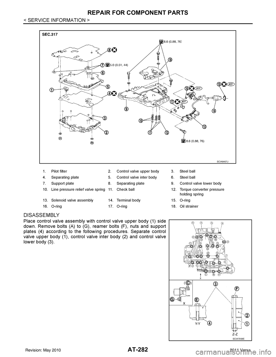
Place control valve assembly with control valve upper body (1) side
down. Remove bolts (A) to (G), reamer bolts (F), nuts and support
plates (4) according to the following procedures. Separate control
valve upper body (1), control valve inter body (2) and control valve
lower body (3).
1. Pilot filter2. Control valve upper body 3. Steel ball
4. Separating plate 5. Control valve inter body 6. Steel ball
7. Support plate 8. Separating plate9. Control valve lower body
10. Line pressure relief valve spring 11. Check ball 12. Torque converter pressure
holding spring
13. Solenoid valve assembly 14. Terminal body 15. O-ring
16. O-ring 17. O-ring18. Oil strainer
SCIA8407J
SCIA7058E
Revision: May 2010 2011 Versa
Page 304 of 3787
REPAIR FOR COMPONENT PARTSAT-287
< SERVICE INFORMATION >
DE
F
G H
I
J
K L
M A
B
AT
N
O P
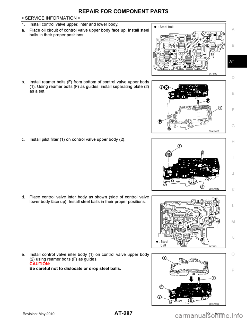
1. Install control valve upper, inter and lower body.
a. Place oil circuit of control valve upper body face up. Install steel balls in their proper positions.
b. Install reamer bolts (F) from bottom of control valve upper body (1). Using reamer bolts (F) as guides, install separating plate (2)
as a set.
c. Install pilot filter (1) on control valve upper body (2).
d. Place control valve inter body as shown (side of control valve lower body face up). Install steel balls in their proper positions.
e. Install control valve inter body (1) on control valve upper body (2) using reamer bolts (F) as guides.
CAUTION:
Be careful not to dislocate or drop steel balls.
SAT871J
SCIA7010E
SCIA7011E
SAT870J
SCIA7012E
Revision: May 2010 2011 Versa
Page 863 of 3787
BR-16
< SERVICE INFORMATION >
BRAKE MASTER CYLINDER
INSTALLATION
CAUTION:
• Refill using recommended brake fluid. Refer to MA-14, "
Fluids and Lubricants".
• Never reuse drained brake fluid.
• Check if the rod of primary piston has dust or scratches.
1. Install master cylinder to brake booster assembly, and tighten nuts to the specified torque.
CAUTION:
• Do not damage or strain rod of primary piston.
• Apply silicone grease for O-ring, primary piston rod andto inside of booster.
2. Install brake tube to master cylinder, and temporarily tighten the flare nuts on the brake tube to master cyl- inder by hand.
3. Install brake tube to brake hose, then tighten flare nut to the specified torque using a flare nut torque
wrench. Refer to BR-11, "
Hydraulic Circuit".
4. Connect the clutch hose to the reservoir tank, if equipped.
5. Connect brake fluid level switch harness connector.
6. Install the air cleaner. Refer to EM-135, "
Removal and Installation".
7. Install the air duct. Refer to EM-135, "
Removal and Installation".
8. Install the battery. Refer to SC-7, "
Removal and Installation".
9. Refill with new brake fluid and bleed the air from the brake hydraulic system. Refer toBR-9, "
Bleeding
Brake System".
Disassembly and AssemblyINFOID:0000000005928404
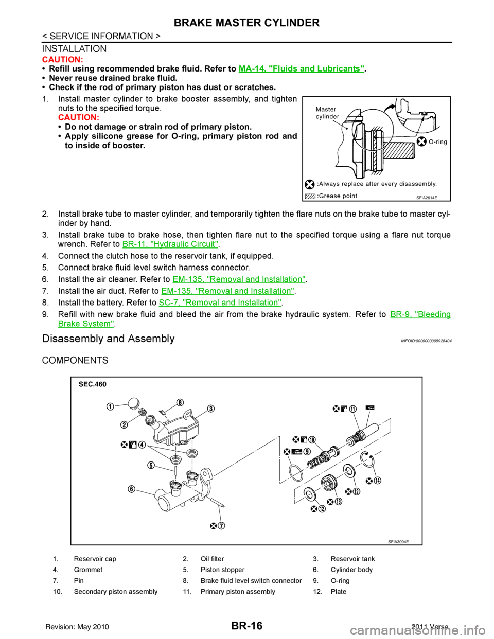
COMPONENTS
SFIA2614E
1. Reservoir cap2. Oil filter 3. Reservoir tank
4. Grommet 5. Piston stopper 6. Cylinder body
7. Pin 8. Brake fluid level switch connector 9. O-ring
10. Secondary piston assembly 11. Primary piston assembly 12. Plate
SFIA3094E
Revision: May 2010 2011 Versa
Page 1073 of 3787
![NISSAN TIIDA 2011 Service Repair Manual CVT-18
< SERVICE INFORMATION >[RE0F08B]
CVT FLUID
b. If one or more pieces of debris are found that are over 1 mm
(0.040 in) in size and/or peeled clutch facing material is found in
the coffee filter,](/manual-img/5/57396/w960_57396-1072.png "NISSAN TIIDA 2011 Service Repair Manual CVT-18
< SERVICE INFORMATION >[RE0F08B]
CVT FLUID
b. If one or more pieces of debris are found that are over 1 mm
(0.040 in) in size and/or peeled clutch facing material is found in
the coffee filter,")
CVT-18
< SERVICE INFORMATION >[RE0F08B]
CVT FLUID
b. If one or more pieces of debris are found that are over 1 mm
(0.040 in) in size and/or peeled clutch facing material is found in
the coffee filter, the fluid cooler is not serviceable. The radiator/
fluid cooler must be replac ed and the inspection procedure is
ended.
CVT FLUID COOLER FINAL INSPECTION
After performing all procedures, ensure that all remaining oil is cleaned from all components.
SCIA7031E
Revision: May 2010 2011 Versa
Page 1096 of 3787
![NISSAN TIIDA 2011 Service Repair Manual TROUBLE DIAGNOSISCVT-41
< SERVICE INFORMATION > [RE0F08B]
D
E
F
G H
I
J
K L
M A
B
CVT
N
O P
Road TestINFOID:0000000005928754
DESCRIPTION
• The purpose of the test is to determine overall performance](/manual-img/5/57396/w960_57396-1095.png "NISSAN TIIDA 2011 Service Repair Manual TROUBLE DIAGNOSISCVT-41
< SERVICE INFORMATION > [RE0F08B]
D
E
F
G H
I
J
K L
M A
B
CVT
N
O P
Road TestINFOID:0000000005928754
DESCRIPTION
• The purpose of the test is to determine overall performance")
TROUBLE DIAGNOSISCVT-41
< SERVICE INFORMATION > [RE0F08B]
D
E
F
G H
I
J
K L
M A
B
CVT
N
O P
Road TestINFOID:0000000005928754
DESCRIPTION
• The purpose of the test is to determine overall performance of CVT and analyze causes of problems.
• The road test consists of the following three parts:
1. “Check Before Engine Is Started” CVT-42
.
2. “Check at Idle”CVT-42
.
3. “Cruise Test”CVT-43
.
• Before road test, familiarize yourself with all test procedures and items to check.
• Perform tests on all items until specified symptom is found. Trou-
bleshoot items which check out No Good after road test.
Judgement Possible cause
Idle speed Low for all positions
(“P”, “R”, “N”, “D”, “L”)
Possible causes include malfunctions in the pressure supply system and low oil pump output.
For example
• Oil pump wear
• Pressure regulator valve or plug sticking or spring fatigue
• Oil strainer
⇒ oil pump ⇒ pressure regulator valve passage oil leak
• Engine idle speed too low
Only low for a specific
position Possible causes include an oil pressure leak in a passage or device related to the position after
the pressure is distributed by the manual valve.
High Possible causes include a sensor malfunction or malfunction in the line pressure adjustment
function.
For example
• Accelerator pedal position signal malfunction
• CVT fluid temperature sensor malfunction
• Line pressure solenoid) malfunction (sticking in OFF state, filter clog, cut line)
• Pressure regulator valve or plug sticking
Stall speed Line pressure does
not rise higher than
the line pressure for
idle.
Possible causes include a sensor malfunction or malfunction in the pressure adjustment func-
tion.
For example
• Accelerator pedal position signal malfunction
•TCM malfunction
• Line pressure solenoid) malfunction (shorting, sticking in ON state)
• Pressure regulator valve or plug sticking
The pressure rises,
but does not enter the
standard position. Possible causes include malfunctions in the pressure supply system and malfunction in the pres-
sure adjustment function.
For example
• Accelerator pedal position signal malfunction
• Line pressure solenoid) malfunction (sticking, filter clog)
• Pressure regulator valve or plug sticking
Only low for a specific
position Possible causes include an oil pressure leak in a passage or device related to the position after
the pressure is distributed by the manual valve.
SAT786A
SAT496G
Revision: May 2010
2011 Versa