2011 NISSAN TIIDA high beam
[x] Cancel search: high beamPage 3049 of 3787
HEADLAMP (FOR USA)LT-17
< SERVICE INFORMATION >
C
DE
F
G H
I
J
L
M A
B
LT
N
O P
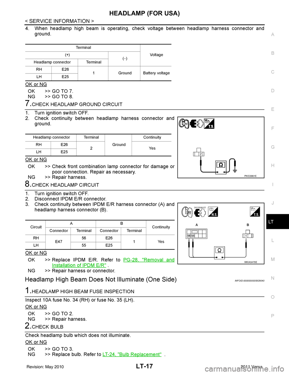
4. When headlamp high beam is operating, check voltage between headlamp harness connector and ground.
OK or NG
OK >> GO TO 7.
NG >> GO TO 8.
7.CHECK HEADLAMP GROUND CIRCUIT
1. Turn ignition switch OFF.
2. Check continuity between headlamp harness connector and ground.
OK or NG
OK >> Check front combination lamp connector for damage or poor connection. Repair as necessary.
NG >> Repair harness.
8.CHECK HEADLAMP CIRCUIT
1. Turn ignition switch OFF.
2. Disconnect IPDM E/R connector.
3. Check continuity between IPDM E/R harness connector (A) and headlamp harness connector (B).
OK or NG
OK >> Replace IPDM E/R. Refer to PG-28, "Removal and
Installation of IPDM E/R" .
NG >> Repair harness or connector.
Headlamp High Beam Does No t Illuminate (One Side)INFOID:0000000005929040
1.HEADLAMP HIGH BEAM FUSE INSPECTION
Inspect 10A fuse No. 34 (RH) or fuse No. 35 (LH).
OK or NG
OK >> GO TO 2.
NG >> Repair harness.
2.CHECK BULB
Check headlamp bulb which does not illuminate.
OK or NG
OK >> GO TO 3.
NG >> Replace bulb. Refer to LT-24, "
Bulb Replacement" .
Te r m i n a l
Vo l ta g e
(+)
(−)
Headlamp connector Terminal
RH E26 1Ground Battery voltage
LH E25
Headlamp connector Terminal
Ground Continuity
RH E26 2Y es
LH E25
PKIC0961E
Circuit AB
Continuity
Connector Terminal Connector Terminal
RH E47 56 E26
1 Yes
LH 55 E25
WKIA5470E
Revision: May 2010 2011 Versa
Page 3050 of 3787
LT-18
< SERVICE INFORMATION >
HEADLAMP (FOR USA)
3.CHECK HEADLAMP INPUT SIGNAL
1. Turn ignition switch OFF.
2. Disconnect headlamp connector.
3. Lighting switch is turned to HIGH position.
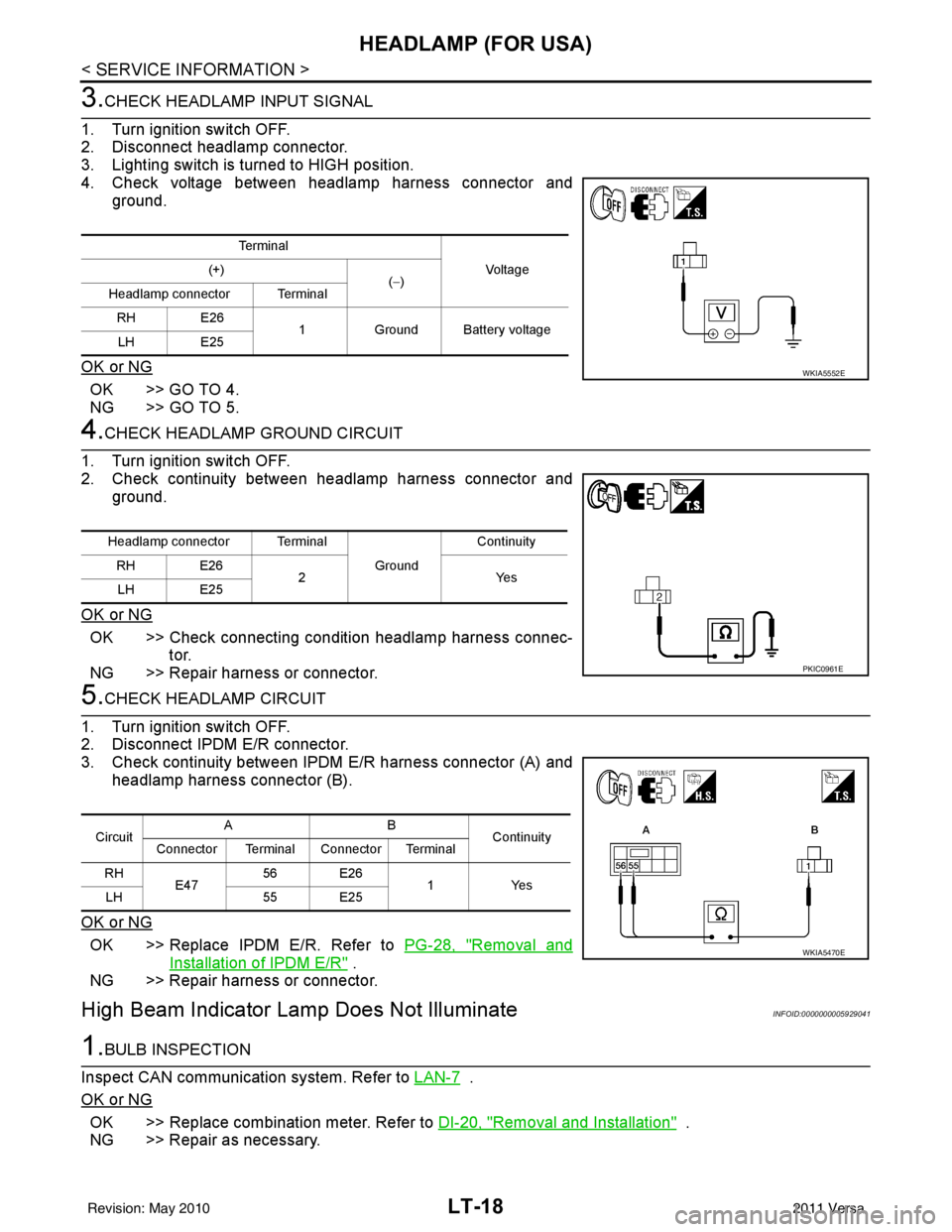
4. Check voltage between headlamp harness connector and ground.
OK or NG
OK >> GO TO 4.
NG >> GO TO 5.
4.CHECK HEADLAMP GROUND CIRCUIT
1. Turn ignition switch OFF.
2. Check continuity between headlamp harness connector and ground.
OK or NG
OK >> Check connecting condition headlamp harness connec- tor.
NG >> Repair harness or connector.
5.CHECK HEADLAMP CIRCUIT
1. Turn ignition switch OFF.
2. Disconnect IPDM E/R connector.
3. Check continuity between IPDM E/R harness connector (A) and
headlamp harness connector (B).
OK or NG
OK >> Replace IPDM E/R. Refer to PG-28, "Removal and
Installation of IPDM E/R" .
NG >> Repair harness or connector.
High Beam Indicator Lam p Does Not IlluminateINFOID:0000000005929041
1.BULB INSPECTION
Inspect CAN communication system. Refer to LAN-7
.
OK or NG
OK >> Replace combination meter. Refer to DI-20, "Removal and Installation" .
NG >> Repair as necessary.
Te r m i n a l
Voltag e
(+)
(−)
Headlamp connector Terminal
RH E26 1Ground Battery voltage
LH E25
WKIA5552E
Headlamp connector Terminal
Ground Continuity
RH E26 2Y es
LH E25
PKIC0961E
Circuit AB
Continuity
Connector Terminal Connector Terminal
RH E47 56 E26
1Yes
LH 55 E25
WKIA5470E
Revision: May 2010 2011 Versa
Page 3055 of 3787
HEADLAMP (FOR USA)LT-23
< SERVICE INFORMATION >
C
DE
F
G H
I
J
L
M A
B
LT
N
O P
Aiming AdjustmentINFOID:0000000005929045
PREPARATION BEFORE ADJUSTING
Before performing aiming adjustment, check the following.
1. Keep all tires inflated to correct pressures.
2. Place vehicle on level surface.
3. See that there is no-load in vehicle other than the driver (or equivalent weight placed in driver's position). Coolant, engine oil filled up to correct level and full fuel tank, spare tire, jack and tools are properly
stowed.
LOW BEAM AND HIGH BEAM
1. Turn headlamp low beam ON.
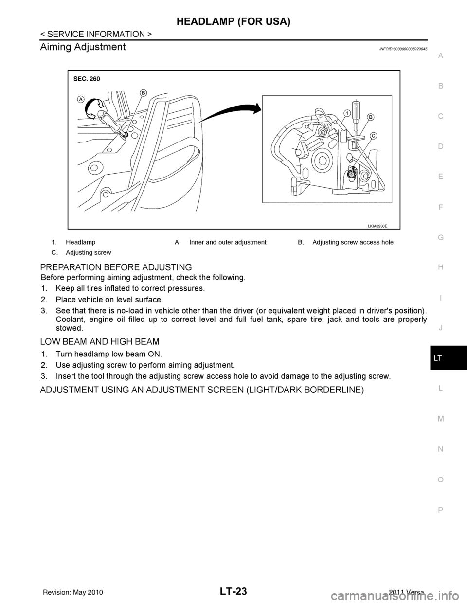
2. Use adjusting screw to perform aiming adjustment.
3. Insert the tool through the adjusting screw acce ss hole to avoid damage to the adjusting screw.
ADJUSTMENT USING AN ADJUSTMENT SCREEN (LIGHT/DARK BORDERLINE)
1. HeadlampA. Inner and outer adjustment B. Adjusting screw access hole
C. Adjusting screw
LKIA0930E
Revision: May 2010 2011 Versa
Page 3056 of 3787
LT-24
< SERVICE INFORMATION >
HEADLAMP (FOR USA)
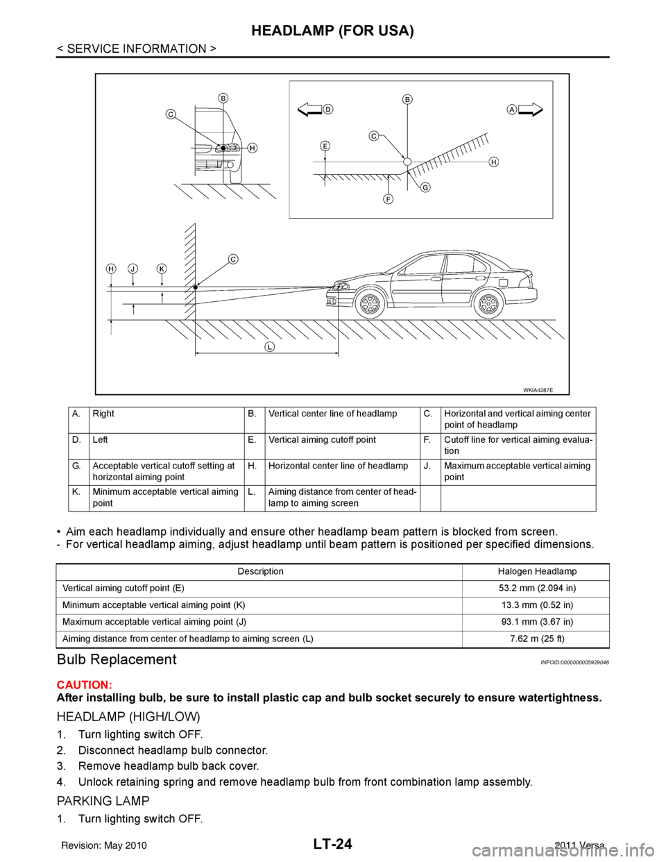
• Aim each headlamp individually and ensure other headlamp beam pattern is blocked from screen.
- For vertical headlamp aiming, adjust headlamp until beam pattern is positioned per specified dimensions.
Bulb ReplacementINFOID:0000000005929046
CAUTION:
After installing bulb, be sure to install plastic cap and bulb socket securely to ensure watertightness.
HEADLAMP (HIGH/LOW)
1. Turn lighting switch OFF.
2. Disconnect headlamp bulb connector.
3. Remove headlamp bulb back cover.
4. Unlock retaining spring and remove headlamp bulb from front combination lamp assembly.
PA R K I N G L A M P
1. Turn lighting switch OFF.
A. Right B. Vertical center line of headlamp C. Horizontal and vertical aiming center
point of headlamp
D. Left E. Vertical aiming cutoff point F. Cutoff line for vertical aiming evalua-
tion
G. Acceptable vertical cutoff setting at horizontal aiming point H. Horizontal center line of headlamp J. Maximum acceptable vertical aiming
point
K. Minimum acceptable vertical aiming point L. Aiming distance from center of head-
lamp to aiming screen
WKIA4287E
Description Halogen Headlamp
Vertical aiming cutoff point (E) 53.2 mm (2.094 in)
Minimum acceptable vertical aiming point (K) 13.3 mm (0.52 in)
Maximum acceptable vertical aiming point (J) 93.1 mm (3.67 in)
Aiming distance from center of headlamp to aiming screen (L) 7.62 m (25 ft)
Revision: May 2010 2011 Versa
Page 3060 of 3787
![NISSAN TIIDA 2011 Service Repair Manual LT-28
< SERVICE INFORMATION >
HEADLAMP (FOR CANADA) - DAYTIME LIGHT SYSTEM -
• through 10A fuse [No. 3, located in fuse block (J/B)]
• to combination meter terminal 28.
With the ignition switch in](/manual-img/5/57396/w960_57396-3059.png "NISSAN TIIDA 2011 Service Repair Manual LT-28
< SERVICE INFORMATION >
HEADLAMP (FOR CANADA) - DAYTIME LIGHT SYSTEM -
• through 10A fuse [No. 3, located in fuse block (J/B)]
• to combination meter terminal 28.
With the ignition switch in")
LT-28
< SERVICE INFORMATION >
HEADLAMP (FOR CANADA) - DAYTIME LIGHT SYSTEM -
• through 10A fuse [No. 3, located in fuse block (J/B)]
• to combination meter terminal 28.
With the ignition switch in the ACC or ON position, power is supplied
• through 10A fuse [No. 20, located in fuse block (J/B)]
• to BCM terminal 11.
Ground is supplied
• to BCM terminal 67 and
• to combination meter terminals 21, 22 and 23
• through grounds M57 and M61,
• to IPDM E/R terminals 39 and 59
• through grounds E15 and E24,
HEADLAMP OPERATION
Low Beam Operation
With the lighting switch in 2ND position, the BCM re ceives an input signal requesting the headlamps to illumi-
nate. This input signal is communicated to the IPDM E/R via the CAN communication lines. The CPU located
in the IPDM E/R controls the headlamp low re lay coil, which when energized, directs power
• through 15A fuse (No. 41, located in IPDM E/R)
• through IPDM E/R terminal 54
• to daytime light relay 2 terminals 1 and 5 (energizing the relay),
• through daytime light relay 2 terminal 3
• to front combination lamp RH terminal 3, and
• through 15A fuse (No. 40, located in IPDM E/R)
• through IPDM E/R terminal 52
• to front combination lamp LH terminal 3.
Ground is supplied
• to front combination lamp LH terminal 2
• through grounds E15 and E24,
• to headlamp RH terminal 2 via
• daytime light relay 1 terminals 3 and 4
• through grounds E15 and E24.
With power and ground supplied, low beam headlamps illuminate.
High Beam/Flash-to-Pass Operation
With the lighting switch in 2ND position and high beam s witch in the HIGH position, the BCM receives input
signal requesting the headlamp high beams to illuminate. The flash-to-pass feature can be used any time and
also sends a signal to the BCM. This input signal is communicated to the IPDM E/R and the combination
meter via the CAN communication lines. The CPU locat ed in the IPDM E/R controls the headlamp high relay
coil, which when energized, directs power
• through 10A fuse (No. 34, located in IPDM E/R)
• through IPDM E/R terminal 56
• to front combination lamp RH terminal 1, and
• through 10A fuse (No. 35, located in IPDM E/R)
• through IPDM E/R terminal 55
• to front combination lamp LH terminal 1.
Ground is supplied
• to front combination lamp LH terminal 2
• through grounds E15 and E24, and
• to front combination lamp RH terminal 2 via
• daytime light relay 1 terminals 3 and 4
• through grounds E15 and E24.
With power and ground supplied, the high beam headlamps illuminate.
The BCM sends a signal to the combination meter requesting the high beam indicator lamp to turn ON.
Daytime Light System Operation
With the lighting switch in the OFF or 1ST position (parking lamps ON), the BCM receives inputs requesting
the headlights off. If the parking brake is released and the engine is running, the BCM then sends a signal, via
the CAN communication lines, requesting the IPDM E/R to activate the daytime light system. The CPU located
in the IPDM E/R controls the daytime light relay 1 coil, which when energized, directs power
• from daytime light relay 1 terminal 3
• to front combination lamp RH terminal 2,
• through front combination lamp RH high beam terminal 1
Revision: May 2010 2011 Versa
Page 3061 of 3787
HEADLAMP (FOR CANADA) - DAYTIME LIGHT SYSTEM -
LT-29
< SERVICE INFORMATION >
C
D E
F
G H
I
J
L
M A
B
LT
N
O P
• to IPDM E/R terminal 56,
• through 10A fuse (No. 34, located in IPDM E/R) and
• through both de-energized headlamp high relays
• to 10A fuse (No. 35, located in IPDM E/R),
• through IPDM E/R terminal 55
• to front combination lamp LH terminal high beam 1.
Ground is supplied
• to front combination lamp LH terminal 2
• through grounds E15 and E24,
• to daytime light relay 1 terminal 1
• through IPDM E/R terminal 6.
With power and ground supplied, high beam headlamps illuminate at reduced intensity.
COMBINATION SWITCH READING FUNCTION
Refer to BCS-4, "System Description" .
EXTERIOR LAMP BATTERY SAVER CONTROL
Refer to LT-74, "System Description" .
CAN Communication System DescriptionINFOID:0000000005929051
Refer to LAN-7, "System Description" .
Revision: May 2010 2011 Versa
Page 3067 of 3787
HEADLAMP (FOR CANADA) - DAYTIME LIGHT SYSTEM -
LT-35
< SERVICE INFORMATION >
C
D E
F
G H
I
J
L
M A
B
LT
N
O P
How to Perform Trouble DiagnosisINFOID:0000000005929056
1. Confirm the symptom or customer complaint.
2. Understand operation, description and function description. Refer to LT-27, "
System Description" .
3. Perform the Preliminary Check. Refer to LT-35, "
Preliminary Check" .
4. Check symptom and repair or replace the cause of the malfunction.
5. Does the daytime light system operate norma lly? If YES, GO TO 6. If NO, GO TO 4.
6. INSPECTION END
Preliminary CheckINFOID:0000000005929057
CHECK BCM CONFIGURATION
1.CHECK BCM CONFIGURATION
Confirm BCM configuration for "DTRL" is set to "WITH". Refer to BCS-19, "
Configuration" .
OK or NG
OK >> Continue preliminary check. Refer to BCS-16, "BCM Power Supply and Ground Circuit Inspec-
tion" .
NG >> Change BCM configuration for "DTRL" to "WITH". Refer to BCS-19, "
Configuration" .
CHECK POWER SUPPLY AND GROUND CIRCUIT FOR BCM
Refer to BCS-16, "BCM Power Supply and Ground Circuit Inspection" .
CHECK POWER SUPPLY AND GROUND CIRCUIT FOR IPDM E/R
Refer to PG-27, "IPDM E/R Power/Ground Circuit Inspection" .
CONSULT-III Function (BCM)INFOID:0000000005929058
Refer to LT-12, "CONSULT-III Function (BCM)" .
CONSULT-III Function (IPDM E/R)INFOID:0000000005929059
Refer to PG-18, "CONSULT-III Function (IPDM E/R)" .
Daytime Light Control Does Not Operate Properly (High Beam Headlamps Operate
Properly)
INFOID:0000000005929060
1.CHECK DAYTIME LIGHT RELAY 1 FUSE
Inspect daytime light relay fuse 10A fuse (No. 26, located in the fuse and fusible link box).
OK or NG
OK >> GO TO 2.
NG >> Repair harness.
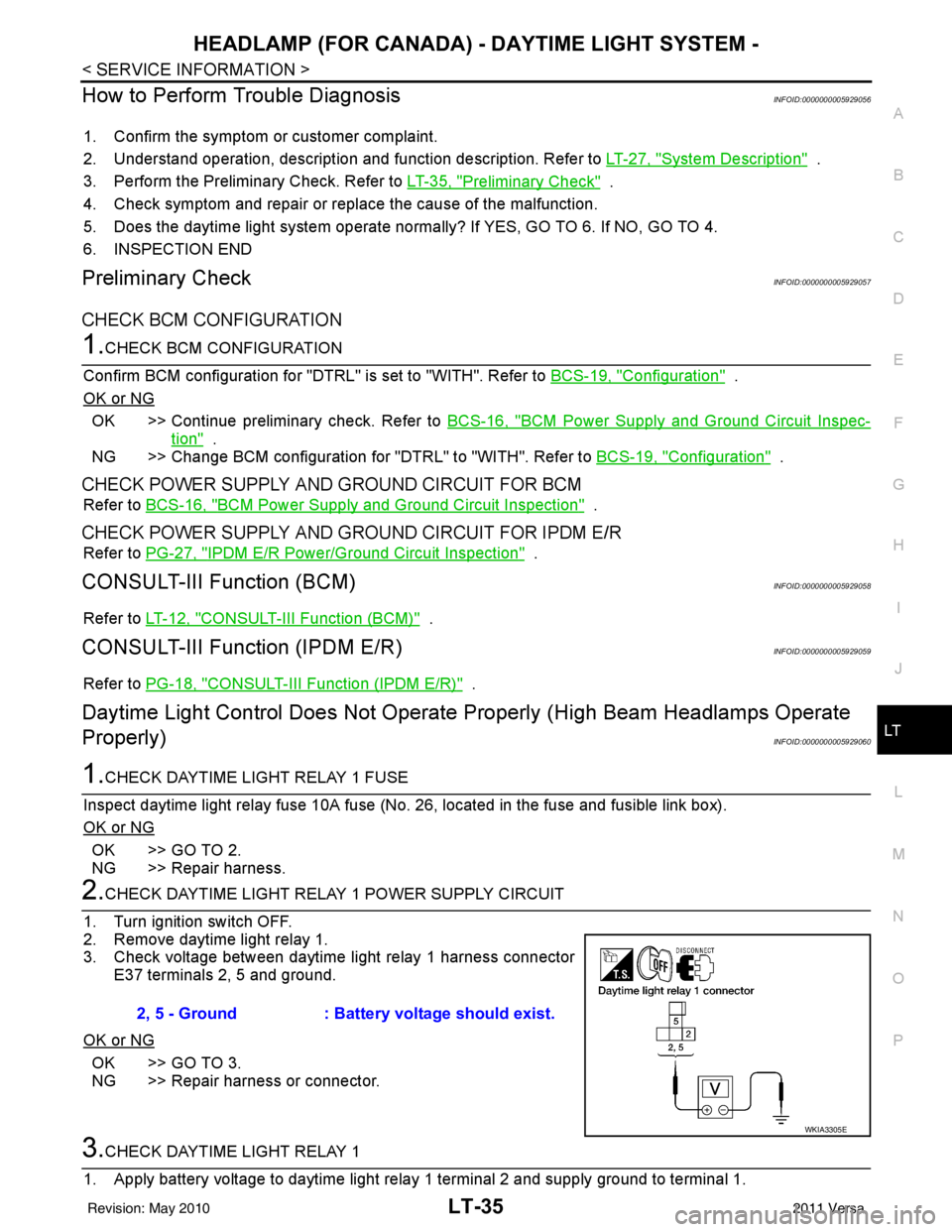
2.CHECK DAYTIME LIGHT RELAY 1 POWER SUPPLY CIRCUIT
1. Turn ignition switch OFF.
2. Remove daytime light relay 1.
3. Check voltage between daytime light relay 1 harness connector E37 terminals 2, 5 and ground.
OK or NG
OK >> GO TO 3.
NG >> Repair harness or connector.
3.CHECK DAYTIME LIGHT RELAY 1
1. Apply battery voltage to daytime light relay 1 terminal 2 and supply ground to terminal 1. 2, 5 - Ground
: Battery voltage should exist.
WKIA3305E
Revision: May 2010 2011 Versa
Page 3069 of 3787
HEADLAMP (FOR CANADA) - DAYTIME LIGHT SYSTEM -
LT-37
< SERVICE INFORMATION >
C
D E
F
G H
I
J
L
M A
B
LT
N
O P
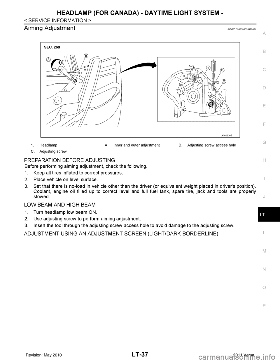
Aiming AdjustmentINFOID:0000000005929061
PREPARATION BEFORE ADJUSTING
Before performing aiming adjustment, check the following.
1. Keep all tires inflated to correct pressures.
2. Place vehicle on level surface.
3. Set that there is no-load in vehicle other than the driv er (or equivalent weight placed in driver's position).
Coolant, engine oil filled up to correct level and full fuel tank, spare tire, jack and tools are properly
stowed.
LOW BEAM AND HIGH BEAM
1. Turn headlamp low beam ON.
2. Use adjusting screw to perform aiming adjustment.
3. Insert the tool through the adjusting screw access hole to avoid damage to the adjusting screw.
ADJUSTMENT USING AN ADJUSTMENT SCREEN (LIGHT/DARK BORDERLINE)
1. Headlamp A. Inner and outer adjustment B. Adjusting screw access hole
C. Adjusting screw
LKIA0930E
Revision: May 2010 2011 Versa