Page 3549 of 3787

RF-26
< ON-VEHICLE REPAIR >
SUNROOF
1. Position the glass lid on sunroof unit assembly.
2. Partially install glass lid bolts. Tighten left front bolt first, then right rear to prevent uneven torque while
tightening remaining bolts.
3. After installation, check sunroof operation and glass lid assembly alignment. Refer to RF-27, "
Fitting
Adjustment" .
SUNSHADE
Removal
1. Remove the headlining. Refer to EI-50, "Component".
2. Remove sunshade stopper RH/LH.
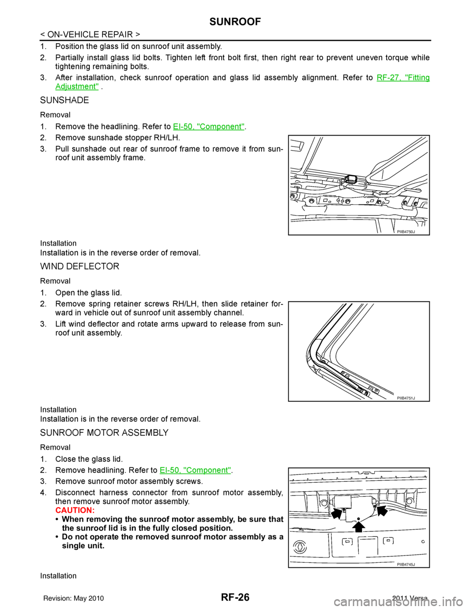
3. Pull sunshade out rear of sunroof frame to remove it from sun- roof unit assembly frame.
Installation
Installation is in the reverse order of removal.
WIND DEFLECTOR
Removal
1. Open the glass lid.
2. Remove spring retainer screws RH/LH, then slide retainer for-
ward in vehicle out of sunroof unit assembly channel.
3. Lift wind deflector and rotate arms upward to release from sun- roof unit assembly.
Installation
Installation is in the reverse order of removal.
SUNROOF MOTOR ASSEMBLY
Removal
1. Close the glass lid.
2. Remove headlining. Refer to EI-50, "
Component".
3. Remove sunroof motor assembly screws.
4. Disconnect harness connector from sunroof motor assembly, then remove sunroof motor assembly.
CAUTION:
• When removing the sunroof motor assembly, be sure that
the sunroof lid is in th e fully closed position.
• Do not operate the removed sunroof motor assembly as a
single unit.
Installation
PIIB4750J
PIIB4751J
PIIB4745J
Revision: May 2010 2011 Versa
Page 3553 of 3787
RF-30
< ON-VEHICLE REPAIR >
SUNROOF
1. Remove headlining. Refer to EI-50, "Component".
2. Visually check drain hoses for: • Proper connection at sunroof unit assembly.
• Damage, pinch, cracks, deterioration.
• Proper fastening and routing on body panels.
3. Pour water through drain hoses to determine watertight performance.
If a damaged or leaking portion in any drain hose is found, replace entire drain hose as an assembly.
1. Drain hose2. Fender 3. Seal
4. Fascia 5. Drain hose rear LH6. Drain hose rear RH
7. Drain hose front LH 8. Drain hose front RH 9. Sunroof unit assembly
Vehicle front
Revision: May 2010 2011 Versa
Page 3675 of 3787

SIDE CURTAIN AIR BAG MODULESRS-41
< ON-VEHICLE REPAIR >
C
DE
F
G
I
J
K L
M A
B
SRS
N
O P
• When servicing the SRS, do not work from directly in front of air bag module.
• Always place the curtain air bag module with deployment side facing upward.
• Do not reuse center pillar upper garnish if removed.
CAUTION:
• Before servicing SRS, turn the ig nition switch OFF, disconnect both battery terminals and wait at
least three minutes.
• Do not use old bolts after removal; replace with new bolts.
• Do not insert any foreign objects (screwdriver, etc.) into air bag module or harness connectors.
• Do not disassemble air bag module.
• Do not expose the side curtain air bag module to temperatures exceeding 90 °C (194 °F).
• Replace the side curtain air bag module if it has been dropped or sustained an impact.
• Do not allow oil, grease or water to come in contact with the
side curtain air bag module.
• Do not attempt to repair or replace damaged direct-connect SRS component connectors. If a direct-connect harness con-
nector is damaged, the harness must be replaced.
1. Disconnect both the negative and positive battery te rminals, then wait at least three minutes.
2. Remove the headlining. Refer to EI-50
.
3. Disconnect side curtain air bag module connector. NOTE:
For removal/installation of the direct-connect SRS connectors,
refer to SRS-7, "
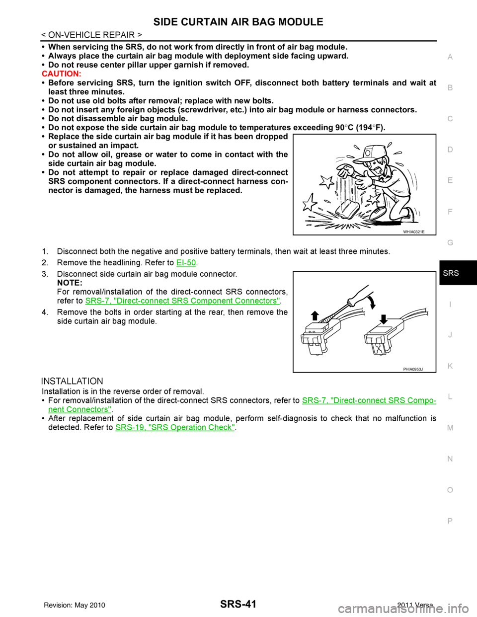
Direct-connect SRS Component Connectors".
4. Remove the bolts in order starting at the rear, then remove the side curtain air bag module.
INSTALLATION
Installation is in the reverse order of removal.
• For removal/installation of the direct-connect SRS connectors, refer to SRS-7, "
Direct-connect SRS Compo-
nent Connectors".
• After replacement of side curtain air bag module, per form self-diagnosis to check that no malfunction is
detected. Refer to SRS-19, "
SRS Operation Check".
WHIA0321E
PHIA0953J
Revision: May 2010 2011 Versa