2011 NISSAN TIIDA brake fluid
[x] Cancel search: brake fluidPage 1105 of 3787
![NISSAN TIIDA 2011 Service Repair Manual CVT-50
< SERVICE INFORMATION >[RE0F08B]
TROUBLE DIAGNOSIS
*: Models without ABS
does not indicate.
WORK SUPPORT MODE
Display Item List
Engine Brake Adjustment
CAUTION:
Mode of “+1”“0”“-1”](/manual-img/5/57396/w960_57396-1104.png "NISSAN TIIDA 2011 Service Repair Manual CVT-50
< SERVICE INFORMATION >[RE0F08B]
TROUBLE DIAGNOSIS
*: Models without ABS
does not indicate.
WORK SUPPORT MODE
Display Item List
Engine Brake Adjustment
CAUTION:
Mode of “+1”“0”“-1”")
CVT-50
< SERVICE INFORMATION >[RE0F08B]
TROUBLE DIAGNOSIS
*: Models without ABS
does not indicate.
WORK SUPPORT MODE
Display Item List
Engine Brake Adjustment
CAUTION:
Mode of “+1”“0”“-1”“-2”“OFF” can be selected by pressing the “UP”“DOWN” on CONSULT-III screen.
However, do not select mode other th an “0” and “OFF”. If the “+1” or “-1” or “-2” is selected, that
might cause the irregular driveability.
Check CVT Fluid Deterioration Date
CAUTION:
Touch “CLEAR” after changing CVT fluid, and then erase “CVTF DETERIORATION DATE”.
SELF-DIAGNOSTIC RESULT MODE
After performing self-diagnosis, place check marks for results on the CVT-31, "How to Perform Trouble Diag-
nosis for Quick and Accurate Repair" . Reference pages are provided following the items.
Display Items List
X: Applicable —: Not applicable
LUSEL SOL OUTSelector lever in “P
” and “N” positions on
Wait at least for 5 seconds with the selector lever
in “R”, “D” and “L” positions off
RANGE Selector lever in “N
” or “P” position. N·P
Selector lever in “R” position. R
Selector lever in “D” position. D
Selector lever in “L” position. L
Item name
Condition Display value (Approx.)
Item name Description
ENGINE BRAKE ADJ. The engine brake level setting can be canceled.
CONFORM CVTF DETERIORTN The CVT fluid deterioration level can be checked.
“ENGINE BRAKE LEVEL”
0: Initial set value (Engine brake level control is ac-
tivated)
OFF: Engine brake level control is deactivated.
“CVTF DETERIORATION DATE”
More than 210000: It is necessary to change CVT fluid.
Less than 210000: It is not necessary to change CVT fluid.
Items (CONSULT-
III screen terms) Malfunction is detected when... TCM self-di-
agnosis OBD-III (DTC)
Reference page
“TRANSMIS-
SION” with
CONSULT-III MIL indicator
lamp*1, “EN-
GINE” with
CONSULT-III or GST
CAN COMM CIR-
CUIT When TCM is not transmitting or receiving CAN communica-
tion signal for 2 seconds or more
U1000 U1000
CVT-56
CONTROL
UNIT(CAN)When detecting error during the initial diagnosis of CAN con-
troller of TCM
U1010 U1010
CVT-59
Revision: May 2010 2011 Versa
Page 1106 of 3787
![NISSAN TIIDA 2011 Service Repair Manual TROUBLE DIAGNOSISCVT-51
< SERVICE INFORMATION > [RE0F08B]
D
E
F
G H
I
J
K L
M A
B
CVT
N
O PBRAKE SWITCH B When the brake switch does not switch to ON or OFF P0703—CVT-60
T/M RANGE SEN-
SOR A When TC](/manual-img/5/57396/w960_57396-1105.png "NISSAN TIIDA 2011 Service Repair Manual TROUBLE DIAGNOSISCVT-51
< SERVICE INFORMATION > [RE0F08B]
D
E
F
G H
I
J
K L
M A
B
CVT
N
O PBRAKE SWITCH B When the brake switch does not switch to ON or OFF P0703—CVT-60
T/M RANGE SEN-
SOR A When TC")
TROUBLE DIAGNOSISCVT-51
< SERVICE INFORMATION > [RE0F08B]
D
E
F
G H
I
J
K L
M A
B
CVT
N
O PBRAKE SWITCH B When the brake switch does not switch to ON or OFF P0703—CVT-60
T/M RANGE SEN-
SOR A When TCM does not receive the the correct voltage signal
(based on the gear position) from the switch
P0705 P0705
CVT-62
FLUID TEMP
SENSOR ADuring running, the CVT fluid temperature sensor signal volt-
age is excessively high or low
P0710 P0710
CVT-67
INPUT SPEED
SENSOR A• Primary speed sensor signal is not input due to an open cir-
cuit
• An unexpected signal is input when vehicle is being driven P0715 P0715
CVT-72
OUTPUT SPEED
SENSOR• Signal from secondary speed sensor not input due to open
or short circuit
• Unexpected signal input during running P0720 P0720
CVT-76
ENGINE SPEED• TCM does not receive the CAN communication signal from
the ECM
• Engine speed is too low while driving P0725 —
CVT-81
INCORRECT GR
RATIOUnexpected gear ratio detected
P0730—CVT-83
TORQUE CON-
VERTER Normal voltage not applied to solenoid due to open or short
circuit
P0740 P0740
CVT-84
TORQUE CON-
VERTER• CVT cannot perform lock-up even if electrical circuit is good
• TCM detects as irregular by comparing difference value
with slip rotation
• There is big difference engine speed and primary speed when TCM lock-up signal is on P0744 P0744
CVT-89
PC SOLENOID A• Normal voltage not applied to solenoid due to open or short
circuit
• TCM detects as irregular by comparing target value with monitor value P0745 P0745
CVT-91
PC SOLENOID AUnexpected gear ratio was detected in the LOW side due to
excessively low line pressure
P0746 P0746
CVT-96
PC SOLENOID BSecondary pressure is too high or too low compared with the
commanded value while driving
P0776 P0776
CVT-98
PC SOLENOID B• Normal voltage not applied to solenoid due to cut line,
short, or the like
• TCM detects as irregular by comparing target value with
monitor value P0778 P0778
CVT-100
FLUID PRESS
SEN/SW ASignal voltage of the secondary pressure sensor is too high
or too low while driving
P0840 P0840
CVT-105
FLUID PRESS
SEN/SW ASecondary fluid pressure is too high compared with the com-
manded value while driving
P0841
—CVT-109
FLUID PRESS
LOW Secondary fluid pressure is too low compared with the com-
manded value while driving
P0868
—C V T- 111
TCM • When the power supply to the TCM is cut OFF, for example
because the battery is removed, and the self-diagnosis
memory function stops
• This is not a malfunction message (Whenever shutting OFF a power supply to the TCM, this message appears on
the screen) P1701
—CVT-113
TP SENSOR TCM does not receive the proper accelerator pedal position
signals (input by CAN communication) from ECM
P1705
—CVT-117
Items (CONSULT-
III screen terms) Malfunction is detected when... TCM self-di-
agnosis OBD-III (DTC)
Reference page
“TRANSMIS-
SION” with
CONSULT-III MIL indicator
lamp*1, “EN-
GINE” with
CONSULT-III
or GST
Revision: May 2010 2011 Versa
Page 1206 of 3787
![NISSAN TIIDA 2011 Service Repair Manual TROUBLE DIAGNOSIS FOR SYMPTOMSCVT-151
< SERVICE INFORMATION > [RE0F08B]
D
E
F
G H
I
J
K L
M A
B
CVT
N
O P
Vehicle Speed Does Not Change in "D" PositionINFOID:0000000005928955
SYMPTOM:
Vehicle speed d](/manual-img/5/57396/w960_57396-1205.png "NISSAN TIIDA 2011 Service Repair Manual TROUBLE DIAGNOSIS FOR SYMPTOMSCVT-151
< SERVICE INFORMATION > [RE0F08B]
D
E
F
G H
I
J
K L
M A
B
CVT
N
O P
Vehicle Speed Does Not Change in \"D\" PositionINFOID:0000000005928955
SYMPTOM:
Vehicle speed d")
TROUBLE DIAGNOSIS FOR SYMPTOMSCVT-151
< SERVICE INFORMATION > [RE0F08B]
D
E
F
G H
I
J
K L
M A
B
CVT
N
O P
Vehicle Speed Does Not Change in "D" PositionINFOID:0000000005928955
SYMPTOM:
Vehicle speed does not change in “D” position while the cruise test.
DIAGNOSTIC PROCEDURE
1.CHECK SELF-DIAGNOSTIC RESULTS
Perform self-diagnosis check. Refer to CVT-48, "
CONSULT-III Function (TRANSMISSION)" .
Is any malfunction detected by self-diagnosis?
YES >> Check the malfunctioning system. Refer to CVT-48, "CONSULT-III Function (TRANSMISSION)" .
NO >> GO TO 2.
2.CHECK CVT POSITION
Check CVT position. Refer to CVT-164, "
Checking of CVT Position"
OK or NG
OK >> GO TO 3.
NG >> Adjust CVT position. Refer to CVT-164, "
Adjustment of CVT Position" .
3.CHECK CVT FLUID LEVEL
Check CVT fluid level. Refer to CVT-14, "
Checking CVT Fluid" .
OK or NG
OK >> GO TO 4.
NG >> Refill CVT fluid.
4.CHECK LINE PRESSURE
Check line pressure at idle. Refer to CVT-37, "
Inspections before Trouble Diagnosis" .
OK or NG
OK >> GO TO 5.
NG >> Check the malfunctioning item. Refer to CVT-37, "
Inspections before Trouble Diagnosis" .
5.CHECK STALL REVOLUTION
Check stall revolution. Refer to CVT-37, "
Inspections before Trouble Diagnosis" .
OK or NG
OK >> GO TO 6.
NG >> Check the malfunctioning item. Refer to CVT-37, "
Inspections before Trouble Diagnosis" .
6.CHECK SYMPTOM
Check again. Refer to CVT-43, "
Cruise Test" .
OK or NG
OK >> INSPECTION END
NG >> GO TO 7.
7.CHECK TCM
1. Check TCM input/output signals. Refer to CVT-46, "
TCM Terminal and Reference Value" .
2. If NG, re-check TCM pin terminals for dam age or loose connection with harness connector.
OK or NG
OK >> Replace the transaxle assembly. Refer to CVT-180, "Removal and Installation" .
NG >> Repair or replace damaged parts.
Vehicle Does Not Decelerate by Engine BrakeINFOID:0000000005928956
SYMPTOM:
Engine brake does not operate when releasing the accelerator pedal while the cruise test.
DIAGNOSTIC PROCEDURE
1.CHECK SELF-DIAGNOSTIC RESULTS
Revision: May 2010 2011 Versa
Page 1249 of 3787
DI-10
< SERVICE INFORMATION >
COMBINATION METERS
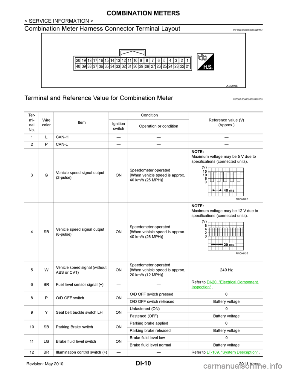
Combination Meter Harness Connector Terminal Layout
INFOID:0000000005929164
Terminal and Reference Va lue for Combination MeterINFOID:0000000005929165
LKIA0698E
Te r -
mi-nal
No. Wire
color Item Condition
Reference value (V)(Approx.)
Ignition
switch Operation or condition
1LCAN-H —— —
2PCAN-L —— —
3G Vehicle speed signal output
(2-pulse) ONSpeedometer operated
[When vehicle speed is approx.
40 km/h (25 MPH)] NOTE:
Maximum voltage may be 5 V due to
specifications (connected units).
4SB Vehicle speed signal output
(8-pulse) ONSpeedometer operated
[When vehicle speed is approx.
40 km/h (25 MPH)] NOTE:
Maximum voltage may be 12 V due to
specifications (connected units).
5W Vehicle speed signal (without
ABS or CVT) ONSpeedometer operated
[When vehicle speed is approx.
20 km/h (12 MPH)] 240 Hz
6 BR Fuel level sensor signal (+) — —Refer to DI-20, "
Electrical Component
Inspection" .
8 P O/D OFF switch ONO/D OFF switch pressed
0
O/D OFF switch released Battery voltage
9 Y Seat belt buckle switch LH ON Unfastened (ON)
0
Fastened (OFF) Battery voltage
10 SB Parking Brake switch ONParking brake applied
0
Parking brake released Battery voltage
11 LG Brake fluid level switch ON Brake fluid level low
0
Brake fluid level normal Battery voltage
12 BR Illumination control switch (+) — —Refer to LT- 1 0 9 , "
System Description" .
PKIC0642E
PKIC0643E
Revision: May 2010 2011 Versa
Page 1250 of 3787
COMBINATION METERSDI-11
< SERVICE INFORMATION >
C
DE
F
G H
I
J
L
M A
B
DI
N
O P
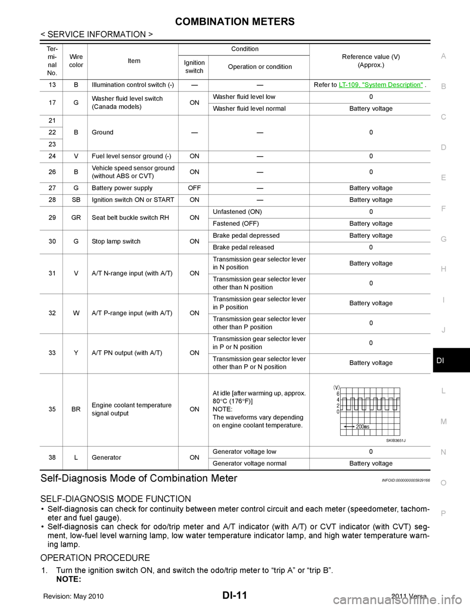
Self-Diagnosis Mode of Combination MeterINFOID:0000000005929166
SELF-DIAGNOSIS MODE FUNCTION
• Self-diagnosis can check for continuity between meter control circuit and each meter (speedometer, tachom- eter and fuel gauge).
• Self-diagnosis can check for odo/trip meter and A/T indi cator (with A/T) or CVT indicator (with CVT) seg-
ment, low-fuel level warning lamp, low water temperature indicator lamp, and high water temperature warn-
ing lamp.
OPERATION PROCEDURE
1. Turn the ignition switch ON, and switch the odo/trip meter to “trip A” or “trip B”. NOTE:
13 B Illumination control switch (-) — —Refer to LT- 1 0 9 , "System Description" .
17 G Washer fluid level switch
(Canada models)
ONWasher fluid level low
0
Washer fluid level normal Battery voltage
21 BGround —— 0
22
23
24 V Fuel level sensor ground (-) ON —0
26 B Vehicle speed sensor ground
(without ABS or CVT) ON
— 0
27 G Battery power supply OFF— Battery voltage
28 SB Ignition switch ON or START ON —Battery voltage
29 GR Seat belt buckle switch RH ON Unfastened (ON)
0
Fastened (OFF) Battery voltage
30 G Stop lamp switch ONBrake pedal depressed
Battery voltage
Brake pedal released 0
31 V A/T N-range input (with A/T) ON Transmission gear selector lever
in N position
Battery voltage
Transmission gear selector lever
other than N position 0
32 W A/T P-range input (with A/T) ON Transmission gear selector lever
in P position
Battery voltage
Transmission gear selector lever
other than P position 0
33 Y A/T PN output (with A/T) ON Transmission gear selector lever
in P or N position
0
Transmission gear selector lever
other than P or N position Battery voltage
35 BR Engine coolant temperature
signal output
ONAt idle [after warming up, approx.
80
°C (176 °F)]
NOTE:
The waveforms vary depending
on engine coolant temperature.
38 L Generator ONGenerator voltage low
0
Generator voltage no rmal Battery voltage
Te r -
mi-
nal
No. Wire
color Item Condition
Reference value (V)
(Approx.)
Ignition
switch Operation or condition
SKIB3651J
Revision: May 2010
2011 Versa
Page 1253 of 3787

DI-14
< SERVICE INFORMATION >
COMBINATION METERS
NOTE:
Some items are not available due to vehicle specification.
*: The monitor will indicate “OFF” even though the brake warning lamp is on if either of the following conditions exist.
• The parking brake is engaged
• The brake fluid level is low
Trouble DiagnosisINFOID:0000000005929168
HOW TO PERFORM TROUBLE DIAGNOSIS
1. Confirm the symptom or customer complaint.
2. Perform preliminary check. Refer to "PRELIMINARY CHECK" .
3. According to the symptom chart, repair or replace the cause of the malfunction. Refer to DI-15, "
Symptom
Chart" .
4. Does the meter operate normally? If so, GO TO 5. If not, GO TO 2.
5. Inspection End.
PRELIMINARY CHECK
1.CHECK SELF-DIAGNOSIS OPERAT ION OF COMBINATION METER
Perform self-diagnosis of combination meter. Refer to DI-11, "
Self-Diagnosis Mode of Combination Meter" .
Does self
-diagnosis mode operate?
TURN IND [ON/OFF] X Indicates [ON/OFF] condition of turn indicator.
OIL W/L [ON/OFF] X Indicates [ON/OFF] condition of oil pressure warning lamp.
VDC/TCS IND [ON/OFF] X Indicates [ON/OFF] condition of VDC OFF indicator lamp.
ABS W/L [ON/OFF] X Indicates [ON/OFF] condition of ABS warning lamp.
SLIP IND [ON/OFF] X Indicates [ON/OFF] condition of SLIP indicator lamp.
BRAKE W/L [ON/OFF] X Indicates [ON/OFF] condition of brake warning lamp.*
KEY G/Y W/L [ON/OFF] X Indicates [ON/OFF] condition of KEY warning lamp (green).
KEY R W/L [ON/OFF] X Indicates [ON/OFF] condition of KEY warning lamp (red).
KEY KNOB W/L [ON/OFF] X Indicates [ON/OFF] condition of LOCK warning lamp.
PNP P SW [ON/OFF] XX Indicates [ON/OFF] condition of inhibitor P switch.
PNP N SW [ON/OFF] XX Indicates [ON/OFF] condition of inhibitor N switch.
O/D OFF SW [ON/OFF] X Indicates [ON/OFF] condition of O/D OFF switch.
BRAKE SW [ON/OFF] X Indicates [ON/OFF] condition of parking brake switch.
P RANGE IND [ON/OFF] XXIndicates [ON/OFF] condition of A/T or CVT shift P range indi-
cator.
R RANGE IND [ON/OFF] XXIndicates [ON/OFF] condition of A/T or CVT shift R range indi-
cator.
N RANGE IND [ON/OFF] XXIndicates [ON/OFF] condition of A/T or CVT shift N range indi-
cator.
D RANGE IND [ON/OFF] XXIndicates [ON/OFF] condition of A/T or CVT shift D range indi-
cator.
2 RANGE IND [ON/OFF] XX Indicates [ON/OFF] condition of A/T shift 2 range indicator.
L RANGE IND [ON/OFF] XX Indicates [ON/OFF] condition of CVT shift L range indicator.
1 RANGE IND [ON/OFF] XX Indicates [ON/OFF] condition of A/T shift 1 range indicator.
CRUISE IND [ON/OFF] X Indicates [ON/OFF] condition of CRUISE indicator.
SET IND [ON/OFF] X Indicates [ON/OFF] condition of SET indicator.
O/D OFF W/L [ON/OFF] X Indicates [ON/OFF] condition of O/D OFF indicator lamp.
EPS W/L [ON/OFF] X Indicates [ON/OFF] condition of EPS warning lamp.
Display item [Unit]
MAIN
SIGNALS SELECTION
FROM MENU Contents
Revision: May 2010
2011 Versa
Page 1320 of 3787
![NISSAN TIIDA 2011 Service Repair Manual EC-26
< BASIC INSPECTION >[HR16DE]
INSPECTION AND ADJUSTMENT
• Each time electric throttle control actuator or ECM is replaced.
• Idle speed or ignition timing is out of specification.
IDLE AIR VO](/manual-img/5/57396/w960_57396-1319.png "NISSAN TIIDA 2011 Service Repair Manual EC-26
< BASIC INSPECTION >[HR16DE]
INSPECTION AND ADJUSTMENT
• Each time electric throttle control actuator or ECM is replaced.
• Idle speed or ignition timing is out of specification.
IDLE AIR VO")
EC-26
< BASIC INSPECTION >[HR16DE]
INSPECTION AND ADJUSTMENT
• Each time electric throttle control actuator or ECM is replaced.
• Idle speed or ignition timing is out of specification.
IDLE AIR VOLUME LEARNING
: Special Repair RequirementINFOID:0000000005929760
1.PRECONDITIONING
Make sure that all of the following conditions are satisfied.
Learning will be cancelled if any of the follo wing conditions are missed for even a moment.
• Battery voltage: More than 12.9 V (At idle)
• Engine coolant temperature: 70 - 100 °C (158 - 212° F)
• Selector lever: P or N (A/T), Neutral (M/T)
• Electric load switch: OFF (Air conditioner, headlamp, rear window defogger)
On vehicles equipped with daytime light systems, if the parking brake is applied before the engine is
started the headlamp will not be illuminated.
• Steering wheel: Neutral (Straight-ahead position)
• Vehicle speed: Stopped
• Transmission: Warmed-up
- A/T models
• With CONSULT-III: Drive vehicle until “FLUID TEMP SE” in “DATA MONITOR” mode of “TRANSMISSION”
system indicates less than 0.9 V.
• Without CONSULT-III: Drive vehicle for 10 minutes.
- M/T models
• Drive vehicle for 10 minutes.
Do you have CONSULT-III?
YES >> GO TO 2.
NO >> GO TO 3.
2.IDLE AIR VOLUME LEARNING
With CONSULT-III
1. Perform Accelerator Pedal Released Position Learning. Refer to EC-25, "
ACCELERATOR PEDAL
RELEASED POSITION LEARNING : Special Repair Requirement".
2. Perform Throttle Valve Closed Position Learning. Refer to EC-25, "
THROTTLE VALVE CLOSED POSI-
TION LEARNING : Special Repair Requirement".
3. Start engine and warm it up to normal operating temperature.
4. Select “IDLE AIR VOL LEARN” in “WORK SUPPORT” mode.
5. Touch “START” and wait 20 seconds.
Is
“CMPLT” displayed on CONSULT-III screen?
YES >> GO TO 4.
NO >> GO TO 5.
3.IDLE AIR VOLUME LEARNING
Without CONSULT-III
NOTE:
• It is better to count the ti me accurately with a clock.
• It is impossible to switch the di agnostic mode when an accelerator pedal position sensor circuit has
a malfunction.
1. Perform Accelerator Pedal Released Position Learning. Refer to EC-25, "
ACCELERATOR PEDAL
RELEASED POSITION LEARNING : Special Repair Requirement".
2. Perform Throttle Valve Closed Position Learning. Refer to EC-25, "
THROTTLE VALVE CLOSED POSI-
TION LEARNING : Special Repair Requirement".
3. Start engine and warm it up to normal operating temperature.
4. Turn ignition switch OFF and wait at least 10 seconds.
5. Confirm that accelerator pedal is fully releas ed, turn ignition switch ON and wait 3 seconds.
6. Repeat the following procedure quickly five times within 5 seconds.
- Fully depress the accelerator pedal.
- Fully release the accelerator pedal.
7. Wait 7 seconds, fully depress the accelerator pedal and keep it for approx. 20 seconds until the MIL stops
blinking and turned ON.
8. Fully release the accelerator pedal within 3 seconds after the MIL turned ON.
Revision: May 2010 2011 Versa
Page 1774 of 3787
![NISSAN TIIDA 2011 Service Repair Manual EC-480
< ECU DIAGNOSIS >[HR16DE]
ECM
P0460 0460 FUEL LEV SEN SLOSH
— 2×AEC-346
P0461 0461 FUEL LEVEL SENSOR — 2×BEC-347
P0462 0462 FUEL LEVL SEN/CIRC — 2×BEC-349
P0463 0463 FUEL LEVL SEN/CIRC](/manual-img/5/57396/w960_57396-1773.png "NISSAN TIIDA 2011 Service Repair Manual EC-480
< ECU DIAGNOSIS >[HR16DE]
ECM
P0460 0460 FUEL LEV SEN SLOSH
— 2×AEC-346
P0461 0461 FUEL LEVEL SENSOR — 2×BEC-347
P0462 0462 FUEL LEVL SEN/CIRC — 2×BEC-349
P0463 0463 FUEL LEVL SEN/CIRC")
EC-480
< ECU DIAGNOSIS >[HR16DE]
ECM
P0460 0460 FUEL LEV SEN SLOSH
— 2×AEC-346
P0461 0461 FUEL LEVEL SENSOR — 2×BEC-347
P0462 0462 FUEL LEVL SEN/CIRC — 2×BEC-349
P0463 0463 FUEL LEVL SEN/CIRC — 2×BEC-349
P0500 0500
VEH SPEED SEN/CIRC*6—2×BEC-351
P0506 0506 ISC SYSTEM — 2×BEC-353
P0507 0507 ISC SYSTEM — 2×BEC-355
P0603 0603 ECM BACK UP/CIRCUIT — 2×BEC-357
P0605 0605 ECM — 1 or 2× or — B EC-359
P0607 0607 ECM —1 (A/T)
2 (M/T) ×
(A/T)
— (M/T) B
EC-361
P0643 0643 SENSOR POWER/CIRC — 1×BEC-362
P0705 0705 T/M RANGE SENSOR A — 2×BAT- 9 0
P0710 0710
FLUID TEMP SENSOR A*9—2×BAT- 9 5
P0720 0720
OUTPUT SPEED SENSOR*6—2×BAT- 1 0 0
P0725 0725 ENGINE SPEED — 2×BAT- 1 0 5
P0731 0731
1GR INCORRECT RATIO*9—2×BAT- 1 0 9
P0732 0732
2GR INCORRECT RATIO*9—2×BAT- 11 2
P0733 0733
3GR INCORRECT RATIO*9—2×BAT- 11 5
P0734 0734
4GR INCORRECT RATIO*9—2×BAT- 11 8
P0740 0740 TORQUE CONVERTER — 2×BAT- 1 2 3
P0744 0744 TORQUE CONVERTER — 2×BAT- 1 2 8
P0745 0745 PC SOLENOID A — 2×BAT- 1 3 3
P0750 0750 SHIFT SOLENOID A — 1×BAT- 1 3 8
P0755 0755 SHIFT SOLENOID B — 1×BAT- 1 4 3
P0850 0850 P-N POS SW/CIRCUIT — 2×BEC-366
P1148 1148 CLOSED LOOP-B1 — 1×AEC-371
P1217 1217 ENG OVER TEMP — 1×BEC-372
P1225 1225 CTP LEARNING-B1 — 2——EC-376
P1226 1226 CTP LEARNING-B1 — 2——EC-378
P1421 1421 COLD START CONTROL — 2×AEC-380
P1610 1610 LOCK MODE — 2——BL-257
P1611 1611 ID DISCORD, IMMU-ECM — 2——BL-257
P1612 1612 CHAIN OF ECM-IMMU — 2——BL-257
P1613 1613 ECM INT CIRC-IMMC — 2——BL-257
P1614 1614 CHAIN OF IMMU-KEY — 2——BL-257
P1615 1615 DIFFERENCE OF KEY — 2——BL-257
P1715 1715 IN PULY SPEED — 2——EC-382
P1760 1760 OVER CLUTCH SOLENOID — 2 ×BAT- 1 4 8
P1805 1805 BRAKE SW/CIRCUIT — 2——EC-383
P2100 2100 ETC MOT PWR-B1 — 1×BEC-387
P2101 2101 ETC FNCTN/CIRC-B1 — 1×BEC-391
DTC*1
Items
(CONSULT-III screen terms) SRT
code Trip MIL Permanent
DTC
group*
4
Reference page
CONSULT-III
GST*
2ECM*3
Revision: May 2010 2011 Versa