Page 3397 of 3787
REFRIGERANT LINESMTC-81
< SERVICE INFORMATION >
C
DE
F
G H
I
K L
M A
B
MTC
N
O P
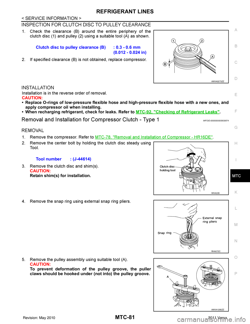
INSPECTION FOR CLUTCH DISC TO PULLEY CLEARANCE
1. Check the clearance (B) around the entire periphery of the clutch disc (1) and pulley (2) usi ng a suitable tool (A) as shown.
2. If specified clearance (B) is not obtained, replace compressor.
INSTALLATION
Installation is in the reverse order of removal.
CAUTION:
• Replace O-rings of low-pressure flexible hose and high-pressure flexible hose with a new ones, and
apply compressor oil when installing.
• When recharging refrigerant, check for leaks. Refer to MTC-92, "
Checking of Refrigerant Leaks".
Removal and Installation for Compressor Clutch - Type 1INFOID:0000000005930874
REMOVAL
1. Remove the compressor. Refer to MTC-78, "Removal and Installation of Compressor - HR16DE".
2. Remove the center bolt by holding the clutch disc steady using Tool.
3. Remove the clutch disc and shim(s). CAUTION:
Retain shim(s) for installation.
4. Remove the snap ring using external snap ring pliers.
5. Remove the pulley assembly using suitable tool (A). CAUTION:
To prevent deformation of the pulley groove, the puller
claws should be hooked under (not into) the pulley groove.
Clutch disc to pulley clearance (B) : 0.3 - 0.6 mm
(0.012 - 0.024 in)
AWIIA0273ZZ
Tool number : (J-44614)
WHA228
RHA072C
AWIIA1285ZZ
Revision: May 2010 2011 Versa
Page 3407 of 3787
REFRIGERANT LINESMTC-91
< SERVICE INFORMATION >
C
DE
F
G H
I
K L
M A
B
MTC
N
O P
Installation is in the reverse order of removal.
CAUTION:
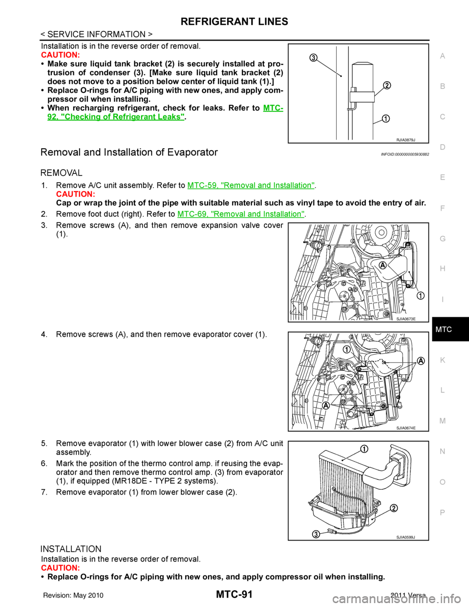
• Make sure liquid tank bracket (2) is securely installed at pro- trusion of condenser (3). [Make sure liquid tank bracket (2)
does not move to a position belo w center of liquid tank (1).]
• Replace O-rings for A/C piping with new ones, and apply com-
pressor oil when installing.
• When recharging refrigerant, check for leaks. Refer to MTC-
92, "Checking of Refrigerant Leaks".
Removal and Installation of EvaporatorINFOID:0000000005930882
REMOVAL
1. Remove A/C unit assembly. Refer to MTC-59, "Removal and Installation".
CAUTION:
Cap or wrap the joint of the pipe with suitable ma terial such as vinyl tape to avoid the entry of air.
2. Remove foot duct (right). Refer to MTC-69, "
Removal and Installation".
3. Remove screws (A), and then remove expansion valve cover (1).
4. Remove screws (A), and then remove evaporator cover (1).
5. Remove evaporator (1) with lower blower case (2) from A/C unit assembly.
6. Mark the position of the thermo control amp. if reusing the evap-
orator and then remove thermo control amp. (3) from evaporator
(1), if equipped (MR18D E - TYPE 2 systems).
7. Remove evaporator (1) from lower blower case (2).
INSTALLATION
Installation is in the reverse order of removal.
CAUTION:
• Replace O-rings for A/C piping with new on es, and apply compressor oil when installing.
RJIA3879J
SJIA0673E
SJIA0674E
SJIA0599J
Revision: May 2010 2011 Versa
Page 3408 of 3787
MTC-92
< SERVICE INFORMATION >
REFRIGERANT LINES
• If reusing the evaporator, install the thermo control amp. at the position marked when removing the
thermo control amp., if equipped (MR18DE - TYPE 2 systems).
• When recharging refrigerant, check for leaks.
Removal and Installation of Expansion ValveINFOID:0000000005930883
REMOVAL
1. Use the recovery/recycling equipment to evacuate the refrigerant.
2. Remove cowl top cover. Refer to EI-24, "
Removal and Installation".
3. Remove lower dash insulator.
4. Disconnect low-pressure flexible hose and high-pressure pipe from evaporator. Refer to MTC-59,
"Removal and Installation".
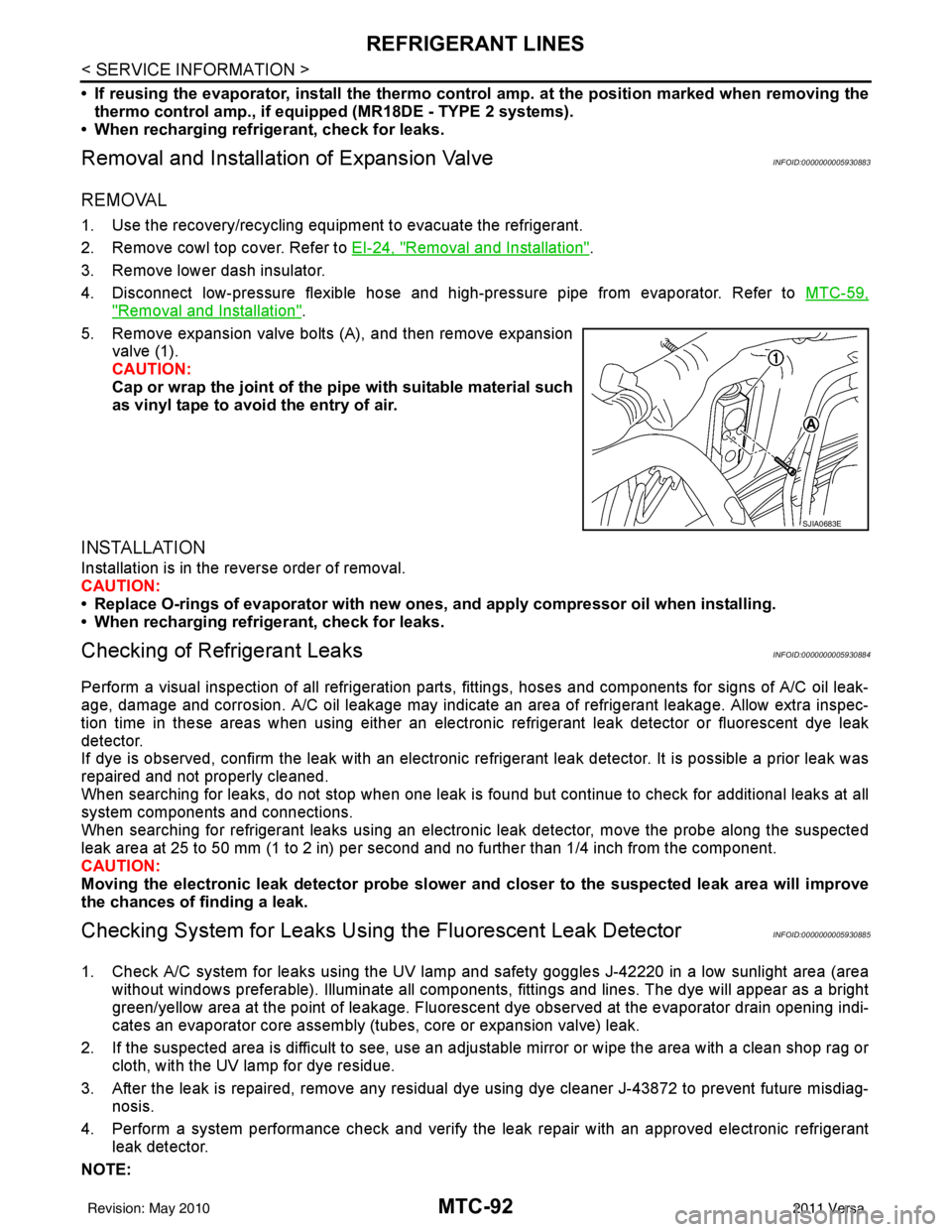
5. Remove expansion valve bolts (A), and then remove expansion valve (1).
CAUTION:
Cap or wrap the joint of the pi pe with suitable material such
as vinyl tape to avoid the entry of air.
INSTALLATION
Installation is in the reverse order of removal.
CAUTION:
• Replace O-rings of evaporator with new ones, and apply compressor oil when installing.
• When recharging refrigerant, check for leaks.
Checking of Refrigerant LeaksINFOID:0000000005930884
Perform a visual inspection of all refrigeration parts, fittings, hoses and components for signs of A/C oil leak-
age, damage and corrosion. A/C oil leakage may indicate an area of refrigerant leakage. Allow extra inspec-
tion time in these areas when using either an electronic refrigerant leak detector or fluorescent dye leak
detector.
If dye is observed, confirm the leak with an electronic refrigerant leak detector. It is possible a prior leak was
repaired and not properly cleaned.
When searching for leaks, do not stop when one leak is found but continue to check for additional leaks at all
system components and connections.
When searching for refrigerant leaks using an electronic leak detector, move the probe along the suspected
leak area at 25 to 50 mm (1 to 2 in) per second and no further than 1/4 inch from the component.
CAUTION:
Moving the electronic leak detector probe slower an d closer to the suspected leak area will improve
the chances of finding a leak.
Checking System for Leaks Using the Fluorescent Leak DetectorINFOID:0000000005930885
1. Check A/C system for leaks using the UV lamp and safety goggles J-42220 in a low sunlight area (area
without windows preferable). Illuminate all components, fittings and lines. The dye will appear as a bright
green/yellow area at the point of leakage. Fluoresce nt dye observed at the evaporator drain opening indi-
cates an evaporator core assembly (tubes, core or expansion valve) leak.
2. If the suspected area is difficult to see, use an adjustable mirror or wipe the area with a clean shop rag or cloth, with the UV lamp for dye residue.
3. After the leak is repaired, remove any residual dye using dye cleaner J-43872 to prevent future misdiag- nosis.
4. Perform a system performance chec k and verify the leak repair with an approved electronic refrigerant
leak detector.
NOTE:
SJIA0683E
Revision: May 2010 2011 Versa