2011 NISSAN TIIDA Engine
[x] Cancel search: EnginePage 100 of 3787

TROUBLE DIAGNOSISAT-83
< SERVICE INFORMATION >
DE
F
G H
I
J
K L
M A
B
AT
N
O P
4. Turn ignition switch ON. (Do not start engine.)
Does OD OFF indicator lamp come on about 2 seconds?
YES >> GO TO 2.
NO >> Stop procedure. Perform AT-180, "
OD OFF Indicator
Lamp Does Not Come On" before proceeding.
2.JUDGEMENT PROCEDURE STEP 1
1. Turn ignition switch OFF.
2. Keep pressing shift lock release button.
3. Move selector lever from “P” to “D” position.
4. Turn ignition switch ON. (Do not start engine.)
5. Keep pressing overdrive control switch while OD OFF indicator lamp is lighting up for 2 seconds. (OD OFF indicator lamp is on.)
6. Keep pressing overdrive control swit ch and shift selector lever to the “2” position. (OD OFF indicator lamp
is on.)
7. Stop pressing overdrive control switch. (OD OFF indicator lamp is on.)
8. Shift selector lever to the “1” position. (OD OFF indicator lamp is on.)
9. Keep pressing overdrive control switch . (OD OFF indicator lamp is off.)
10. Depress accelerator pedal fully while pressing overdrive control switch.
>> GO TO 3.
3.CHECK SELF-DIAGNOSIS CODE
Check OD OFF indicator lamp. Refer to "Judgement of Self-diagnosis Code" .
>>DIAGNOSIS END
Judgement of Self-diagnosis Code
SCIA7140E
Revision: May 2010 2011 Versa
Page 102 of 3787
TROUBLE DIAGNOSISAT-85
< SERVICE INFORMATION >
DE
F
G H
I
J
K L
M A
B
AT
N
O P
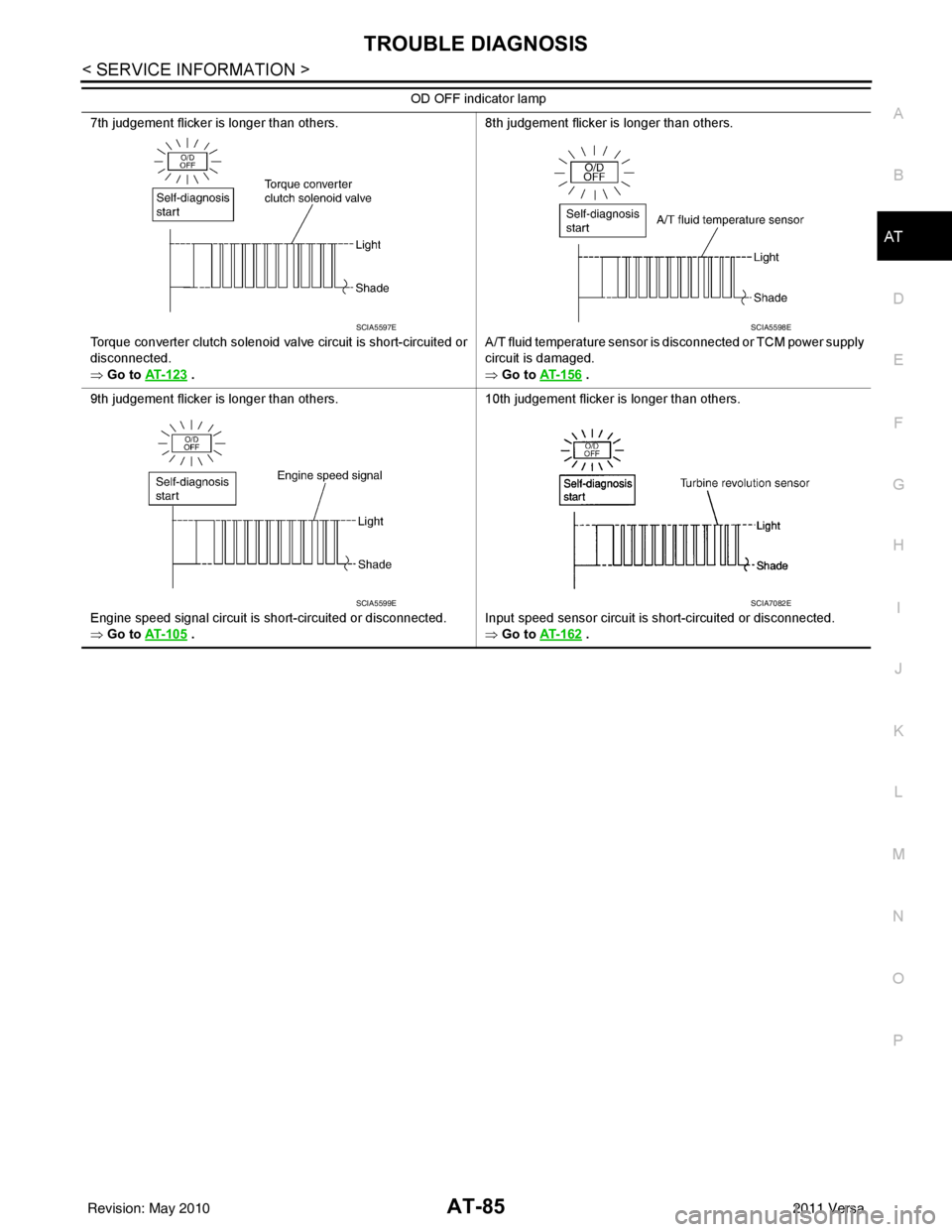
7th judgement flicker is longer than others.
Torque converter clutch solenoid valve circuit is short-circuited or
disconnected.
⇒ Go to AT- 1 2 3
. 8th judgement flicker is longer than others.
A/T fluid temperature sensor is disconnected or TCM power supply
circuit is damaged.
⇒ Go to
AT- 1 5 6 .
9th judgement flicker is longer than others.
Engine speed signal circuit is short-circuited or disconnected.
⇒ Go to AT- 1 0 5
. 10th judgement flicker is longer than others.
Input speed sensor circuit is short-circuited or disconnected.
⇒ Go to
AT- 1 6 2 .
OD OFF indicator lamp
SCIA5597ESCIA5598E
SCIA5599ESCIA7082E
Revision: May 2010
2011 Versa
Page 104 of 3787
U1000 CAN COMM CIRCUITAT-87
< SERVICE INFORMATION >
DE
F
G H
I
J
K L
M A
B
AT
N
O P
U1000 CAN COMM CIRCUIT
DescriptionINFOID:0000000005928107
CAN (Controller Area Network) is a serial communication line for real time application. It is an on-vehicle mul-
tiplex communication line with high data communica tion speed and excellent malfunction detection ability.
Many electronic control units are equipped onto a vehicle, and each control unit shares information and links
with other control units during operation (not independent). In CAN communication, control units are con-
nected with 2 communication lines (CAN H line, CAN L li ne) allowing a high rate of information transmission
with less wiring. Each control unit transmits/recei ves data but selectively reads required data only.
On Board Diagnosis LogicINFOID:0000000005928108
• This is an OBD-II self-diagnostic item.
• Diagnostic trouble code “U1000 CAN COMM CIRCUIT” wit h CONSULT-III or 12th judgement flicker without
CONSULT-III is detected when TCM cannot communicate to other control units.
Possible CauseINFOID:0000000005928109
Harness or connector
(CAN communication line is open or shorted.)
DTC Confirmation ProcedureINFOID:0000000005928110
CAUTION:
If performing this “DTC Confirmation Procedure” again, always turn ignition switch OFF and wait at
least 10 seconds before continuing.
After the repair, perform the following procedure to confirm the malfunction is eliminated.
WITH CONSULT-III
1. Turn ignition switch ON.
2. Select “DATA MONITOR” mode for “TRANSMISSION” with CONSULT-III.
3. Touch “START”.
4. Wait at least 6 seconds or start engine and wait for at least 6 seconds.
5. If DTC is detected, go to AT-89, "
Diagnosis Procedure".
WITH GST
Follow the procedure “WITH CONSULT-III”.
WITHOUT CONSULT-III
1. Turn ignition switch ON.
2. Wait at least 6 seconds or start engine and wait at least 6 seconds.
3. Perform self-diagnosis. Refer to AT-82, "
Diagnosis Procedure without CONSULT-III".
4. If DTC is detected, go to AT-89, "
Diagnosis Procedure".
Revision: May 2010 2011 Versa
Page 106 of 3787
U1000 CAN COMM CIRCUITAT-89
< SERVICE INFORMATION >
DE
F
G H
I
J
K L
M A
B
AT
N
O P
Diagnosis ProcedureINFOID:0000000005928112
1.CHECK CAN COMMUNICATION CIRCUIT
With CONSULT-III1. Turn ignition switch ON and start engine.
2. Select “SELF-DIAG RESULTS” mode for “TRANSMISSION” with CONSULT-III.
Is any malfunction of the
“U1000 CAN COMM CIRCUIT” indicated?
YES >> Print out CONSULT-III screen, Go to LAN section. Refer to LAN-26, "CAN System Specification
Chart".
NO >> INSPECTION END
Revision: May 2010 2011 Versa
Page 107 of 3787

AT-90
< SERVICE INFORMATION >
P0705 TRANSMISSION RANGE SWITCH A
P0705 TRANSMISSION RANGE SWITCH A
DescriptionINFOID:0000000005928113
• The transmission range switch detects the selector lever position and sends a signal to the TCM.
CONSULT-III Reference Value in Data Monitor ModeINFOID:0000000005928114
On Board Diagnosis LogicINFOID:0000000005928115
• This is an OBD-II self-diagnostic item.
• Diagnostic trouble code “P0705 T/M RANGE SWITCH A” with CONSULT-III is detected when TCM does not
receive the correct voltage signal from the switch based on the gear position.
Possible CauseINFOID:0000000005928116
• Harness or connectors [The transmission range switch circuit is open or shorted.]
• Transmission range switch
DTC Confirmation ProcedureINFOID:0000000005928117
CAUTION:
• Always drive vehicle at a safe speed.
• If performing this “DTC Confirmation Procedure” again, always turn ignition switch OFF and wait at
least 10 seconds before continuing.
After the repair, perform the following proc edure to confirm the malfunction is eliminated.
WITH CONSULT-III
1. Turn ignition switch ON. (Do not start engine.)
2. Select “DATA MONITOR” mode for “TRANSMISSION” with CONSULT-III.
3. Touch “START”.
4. Start engine and maintain the following conditions for at least 5 consecutive seconds. VEHICLE SPEED: 10 km/h (6 MPH) or more
THROTTLE POSI: More than 1.0/8
SLCT LVR POSI: “D” position
5. If the check result is NG, go to AT-92, "
Diagnosis Procedure" .
WITH GST
Follow the procedure “WITH CONSULT-III”.
Item name Condition Display value
PN POSI SW When setting selector lever
to “N” or “P” position. ON
When setting selector lever to other positions. OFF
R POSITION SW When setting selector lever to “R” position.
ON
When setting selector lever to other positions. OFF
D POSITION SW When setting selector lever to “D” position.
ON
When setting selector lever to other positions. OFF
2 POSITION SW When setting selector lever to “2” position.
ON
When setting selector lever to other positions. OFF
1 POSITION SW When setting selector lever to “1” position.
ON
When setting selector lever to other positions. OFF
Revision: May 2010 2011 Versa
Page 109 of 3787
AT-92
< SERVICE INFORMATION >
P0705 TRANSMISSION RANGE SWITCH A
Diagnosis Procedure
INFOID:0000000005928119
1.CHECK INPUT SIGNAL
With CONSULT-III
1. Turn ignition switch ON. (Do not start engine.)
2. Select “TCM INPUT SIGNALS” in “DATA MONITOR” mode for “TRANSMISSION” with CONSULT-III.
3. Read out “P·N”, “R”, “D”, “2” and “1” position switches moving selector lever to each position.
OK or NG
OK >> GO TO 6.
NG >> GO TO 3.
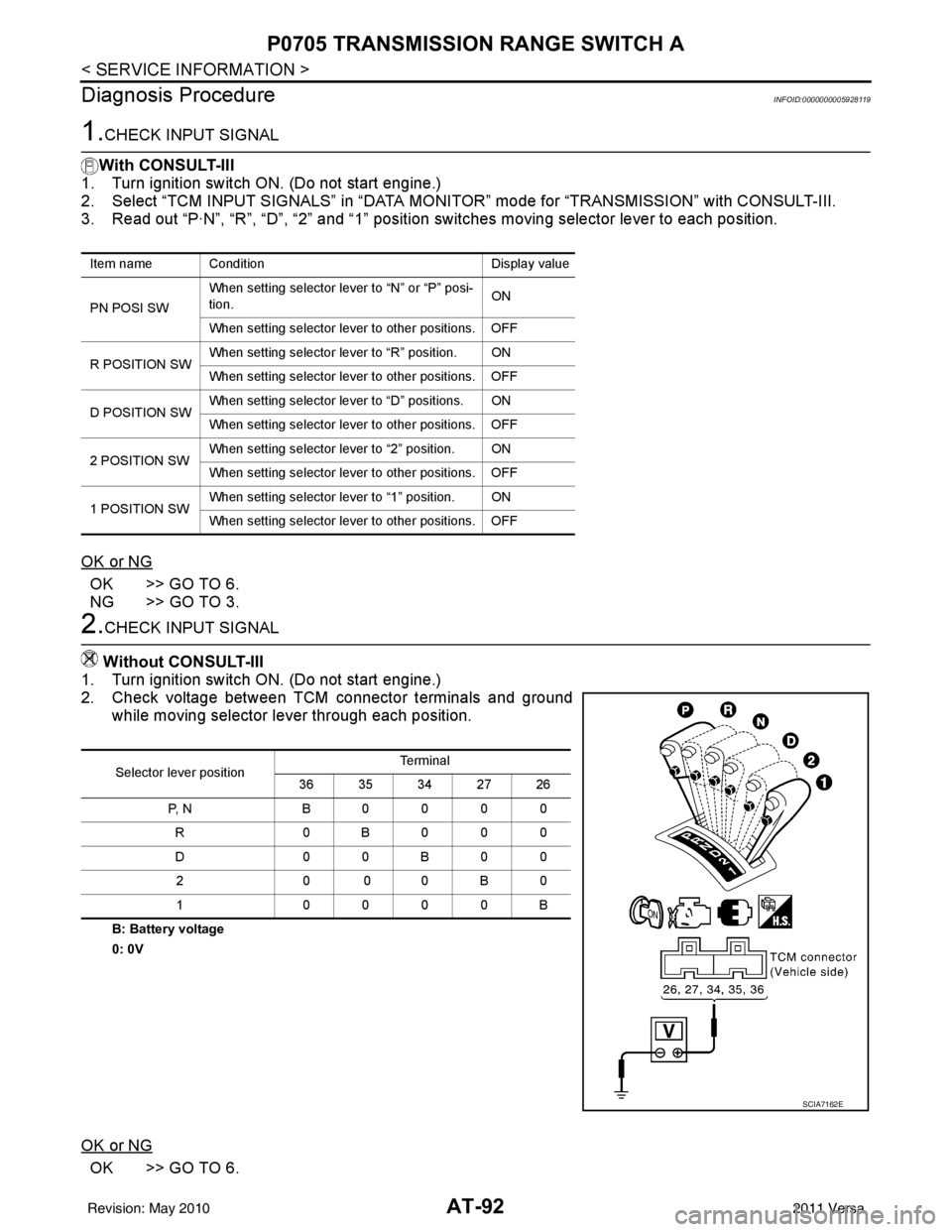
2.CHECK INPUT SIGNAL
Without CONSULT-III
1. Turn ignition switch ON. (Do not start engine.)
2. Check voltage between TCM connector terminals and ground while moving selector lever through each position.
B: Battery voltage
0: 0V
OK or NG
OK >> GO TO 6.
Item name Condition Display value
PN POSI SW When setting selector le
ver to “N” or “P” posi-
tion. ON
When setting selector lever to other positions. OFF
R POSITION SW When setting selector lever to “R” position. ON
When setting selector lever to other positions. OFF
D POSITION SW When setting selector lever to “D” positions. ON
When setting selector lever to other positions. OFF
2 POSITION SW When setting selector lever to “2” position. ON
When setting selector lever to other positions. OFF
1 POSITION SW When setting selector lever to “1” position. ON
When setting selector lever to other positions. OFF
Selector lever position Te r m i n a l
36 35 34 27 26
P, N B0000 R 0B000
D0 0B 00
20 00B 0
1 0000B
SCIA7162E
Revision: May 2010 2011 Versa
Page 112 of 3787
P0710 TRANSMISSION FLUID TEMPERATURE SENSOR AAT-95
< SERVICE INFORMATION >
DE
F
G H
I
J
K L
M A
B
AT
N
O P
P0710 TRANSMISSION FLUI D TEMPERATURE SENSOR A
DescriptionINFOID:0000000005928121
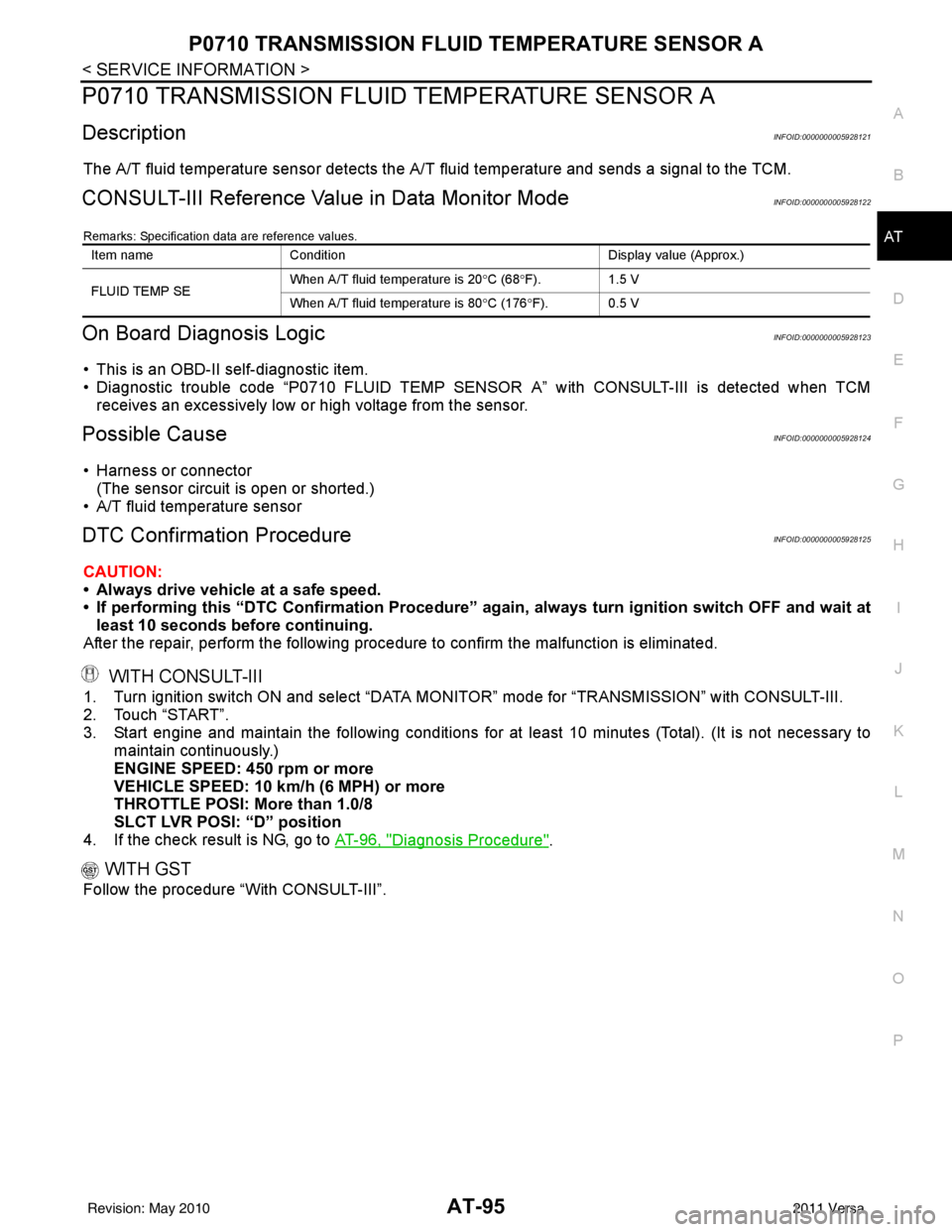
The A/T fluid temperature sensor detects the A/ T fluid temperature and sends a signal to the TCM.
CONSULT-III Reference Value in Data Monitor ModeINFOID:0000000005928122
Remarks: Specification data are reference values.
On Board Diagnosis LogicINFOID:0000000005928123
• This is an OBD-II self-diagnostic item.
• Diagnostic trouble code “P0710 FLUID TEMP SENSOR A” with CONSULT-III is detected when TCM
receives an excessively low or high voltage from the sensor.
Possible CauseINFOID:0000000005928124
• Harness or connector
(The sensor circuit is open or shorted.)
• A/T fluid temperature sensor
DTC Confirmation ProcedureINFOID:0000000005928125
CAUTION:
• Always drive vehicle at a safe speed.
• If performing this “DTC Confirmation Procedure” again, always turn ignition switch OFF and wait at
least 10 seconds before continuing.
After the repair, perform the following procedure to confirm the malfunction is eliminated.
WITH CONSULT-III
1. Turn ignition switch ON and select “DATA MO NITOR” mode for “TRANSMISSION” with CONSULT-III.
2. Touch “START”.
3. Start engine and maintain the following conditions for at least 10 minutes (Total). (It is not necessary to maintain continuously.)
ENGINE SPEED: 450 rpm or more
VEHICLE SPEED: 10 km/h (6 MPH) or more
THROTTLE POSI: More than 1.0/8
SLCT LVR POSI: “D” position
4. If the check result is NG, go to AT-96, "
Diagnosis Procedure".
WITH GST
Follow the procedure “With CONSULT-III”.
Item nameCondition Display value (Approx.)
FLUID TEMP SE When A/T fluid temperature is 20
°C (68 °F). 1.5 V
When A/T fluid temperature is 80 °C (176 °F). 0.5 V
Revision: May 2010 2011 Versa
Page 114 of 3787
P0710 TRANSMISSION FLUID TEMPERATURE SENSOR AAT-97
< SERVICE INFORMATION >
DE
F
G H
I
J
K L
M A
B
AT
N
O P
With CONSULT-III
1. Start engine.
2. Select “TCM INPUT SIGNALS” in “DATA MONI TOR” mode for “TRANSMISSION” with CONSULT-III.
3. Read out the value of “FLUID TEMP SE”.
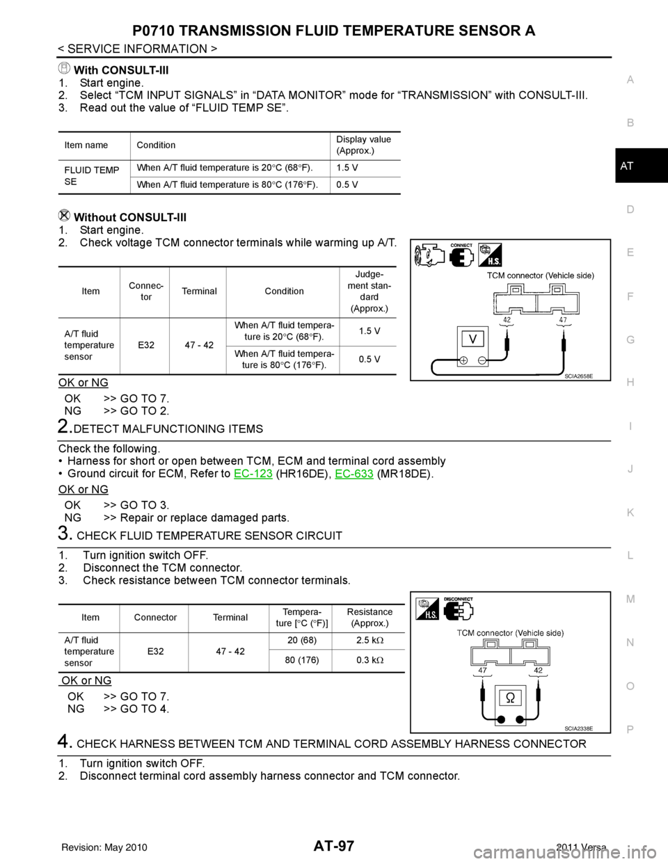
Without CONSULT-III
1. Start engine.
2. Check voltage TCM connector terminals while warming up A/T.
OK or NG
OK >> GO TO 7.
NG >> GO TO 2.
2.DETECT MALFUNCTIONING ITEMS
Check the following.
• Harness for short or open between TCM, ECM and terminal cord assembly
• Ground circuit for ECM, Refer to EC-123
(HR16DE), EC-633 (MR18DE).
OK or NG
OK >> GO TO 3.
NG >> Repair or replace damaged parts.
3. CHECK FLUID TEMPERATURE SENSOR CIRCUIT
1. Turn ignition switch OFF.
2. Disconnect the TCM connector.
3. Check resistance between TCM connector terminals.
OK or NG
OK >> GO TO 7.
NG >> GO TO 4.
4. CHECK HARNESS BETWEEN TCM AND TERMINAL CORD ASSEMBLY HARNESS CONNECTOR
1. Turn ignition switch OFF.
2. Disconnect terminal cord assemb ly harness connector and TCM connector.
Item name Condition Display value
(Approx.)
FLUID TEMP
SE When A/T fluid temperature is 20
°C (68 °F). 1.5 V
When A/T fluid temperature is 80 °C (176 °F). 0.5 V
Item Connec-
tor Terminal
Condition Judge-
ment stan- dard
(Approx.)
A/T fluid
temperature
sensor E32 47 - 42 When A/T fluid tempera-
ture is 20 °C (68 °F). 1.5 V
When A/T fluid tempera- ture is 80 °C (176 °F). 0.5 V
SCIA2658E
Item Connector Terminal Te m p e r a -
ture [ °C ( °F)] Resistance
(Approx.)
A/T fluid
temperature
sensor E32
47 - 42 20 (68) 2.5 k
Ω
80 (176) 0.3 k Ω
SCIA2338E
Revision: May 2010 2011 Versa