2011 NISSAN LATIO stop
[x] Cancel search: stopPage 10 of 3787
2011
QUICK REFERENCE INDEX: VERSA
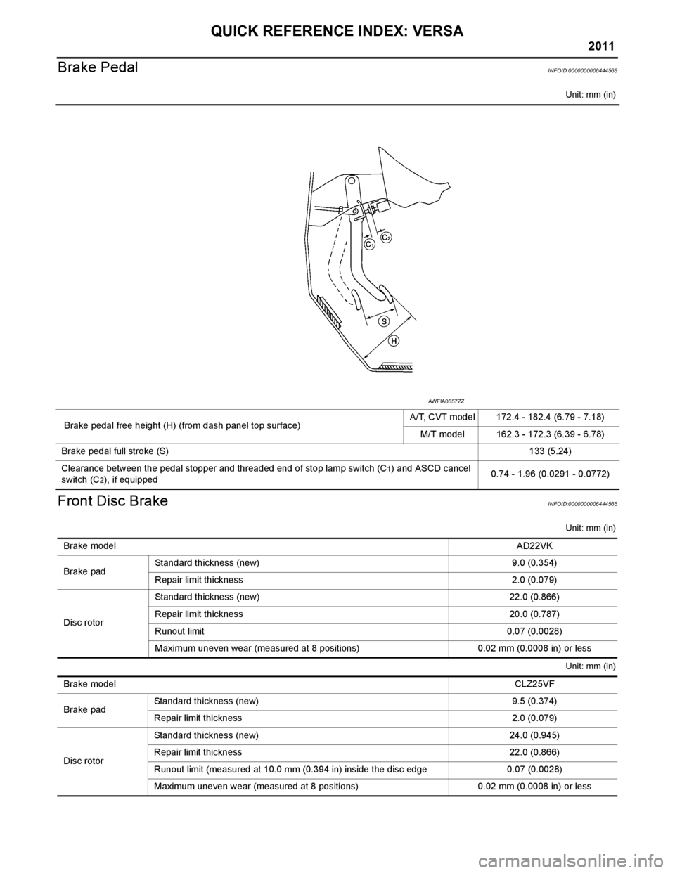
Brake Pedal
INFOID:0000000006444568
Unit: mm (in)
Front Disc BrakeINFOID:0000000006444565
Unit: mm (in)
Unit: mm (in)
Brake pedal free height (H) (from dash panel top surface) A/T, CVT model 172.4 - 182.4 (6.79 - 7.18)
M/T model 162.3 - 172.3 (6.39 - 6.78)
Brake pedal full stroke (S) 133 (5.24)
Clearance between the pedal stopper and threaded end of stop lamp switch (C
1) and ASCD cancel
switch (C
2), if equipped 0.74 - 1.96 (0.0291 - 0.0772)
AWFIA0557ZZ
Brake model
AD22VK
Brake pad Standard thickness (new) 9.0 (0.354)
Repair limit thickness 2.0 (0.079)
Disc rotor Standard thickness (new)
22.0 (0.866)
Repair limit thickness 20.0 (0.787)
Runout limit 0.07 (0.0028)
Maximum uneven wear (measured at 8 positions) 0.02 mm (0.0008 in) or less
Brake model CLZ25VF
Brake pad Standard thickness (new)
9.5 (0.374)
Repair limit thickness 2.0 (0.079)
Disc rotor Standard thickness (new)
24.0 (0.945)
Repair limit thickness 22.0 (0.866)
Runout limit (measured at 10.0 mm (0.394 in) inside the disc edge 0.07 (0.0028)
Maximum uneven wear (measured at 8 positions) 0.02 mm (0.0008 in) or less
Page 15 of 3787

ACC-4
< SERVICE INFORMATION >
ACCELERATOR CONTROL SYSTEM
ACCELERATOR CONTROL SYSTEM
ComponentINFOID:0000000005928709
Removal and InstallationINFOID:0000000005928710
CAUTION:
• Do not disassemble accelerator pedal assembly. Do not remove accelerator pedal position sensor
from accelerator pedal assembly.
• Avoid impact from dropping etc. during handling.
• Be careful to keep accelerator pedal assembly away from water.
REMOVAL
1. Disconnect the negative battery terminal.
2. Disconnect accelerator pedal position sensor harness connector.
3. Remove the bolts and the accelerator pedal assembly.
INSTALLATION
Note the following, and install in the reverse order of removal.
• Insert locating pin into vehicle side to position accelerator pedal assembly. Install bolt to accelerator pedal assembly.
• Align the stud bolt on the floor with the thread hole to insert accelerator pedal stopper until it contacts the
face.
INSPECTION AFTER INSTALLATION
• Make sure that the accelerator pedal moves smoothly within the whole operation range.
• Make sure that the accelerator pedal securely returns to the original position.
• Perform accelerator pedal released position learning. Refer to EC-25, "
ACCELERATOR PEDAL
RELEASED POSITION LEARNING : Special Repair Requirement" (HR16DE), EC-580, "Accelerator Pedal
Released Position Learning" (MR18DE).
1. Accelerator pedal assembly 2. Locating pin 3. Accelerator pedal stopper
: Vehicle front
PBIC3813E
Revision: May 2010 2011 Versa
Page 34 of 3787
A/T FLUIDAT-17
< SERVICE INFORMATION >
DE
F
G H
I
J
K L
M A
B
AT
N
O P
A/T FLUID
Checking A/T FluidINFOID:0000000005928070
1. Warm up engine.
2. Check for A/T fluid leakage.
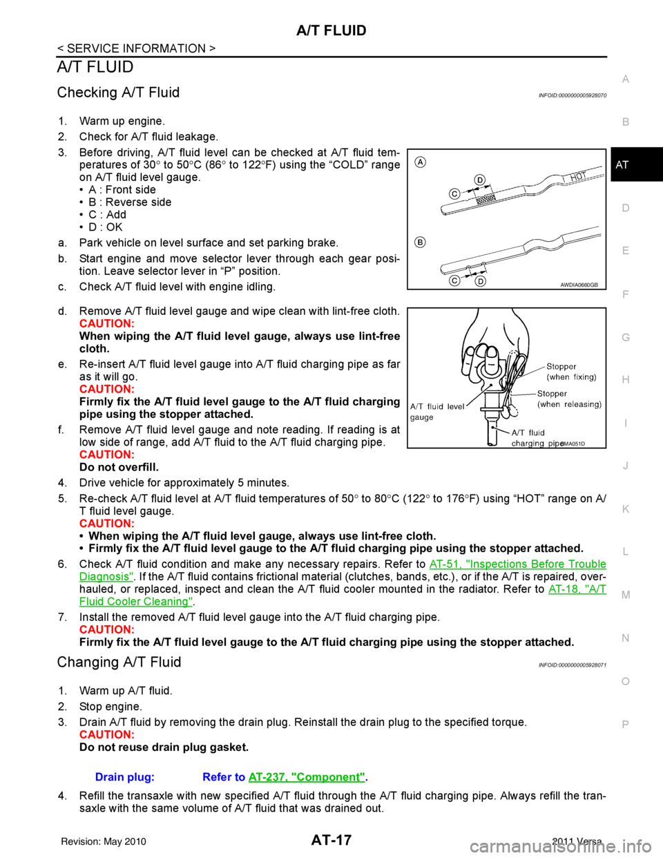
3. Before driving, A/T fluid level can be checked at A/T fluid tem- peratures of 30° to 50°C (86° to 122° F) using the “COLD” range
on A/T fluid level gauge.
• A : Front side
• B : Reverse side
•C : Add
• D : OK
a. Park vehicle on level surface and set parking brake.
b. Start engine and move selector lever through each gear posi- tion. Leave selector lever in “P” position.
c. Check A/T fluid level with engine idling.
d. Remove A/T fluid level gauge and wipe clean with lint-free cloth. CAUTION:
When wiping the A/T fluid l evel gauge, always use lint-free
cloth.
e. Re-insert A/T fluid level gauge into A/T fluid charging pipe as far as it will go.
CAUTION:
Firmly fix the A/T fluid level ga uge to the A/T fluid charging
pipe using the stopper attached.
f. Remove A/T fluid level gauge and note reading. If reading is at low side of range, add A/T fluid to the A/T fluid charging pipe.
CAUTION:
Do not overfill.
4. Drive vehicle for approximately 5 minutes.
5. Re-check A/T fluid level at A/T fluid temperatures of 50° to 80 °C (122° to 176°F) using “HOT” range on A/
T fluid level gauge.
CAUTION:
• When wiping the A/T fluid level gauge, always use lint-free cloth.
• Firmly fix the A/T fluid level ga uge to the A/T fluid charging pipe using the stopper attached.
6. Check A/T fluid condition and make any necessary repairs. Refer to AT-51, "
Inspections Before Trouble
Diagnosis". If the A/T fluid contains frictional material (clutches, bands, etc.), or if the A/T is repaired, over-
hauled, or replaced, inspect and clean the A/T fluid cooler mounted in the radiator. Refer to AT-18, "
A/T
Fluid Cooler Cleaning".
7. Install the removed A/T fluid level gauge into the A/T fluid charging pipe. CAUTION:
Firmly fix the A/T fluid level gaug e to the A/T fluid charging pipe using the stopper attached.
Changing A/T FluidINFOID:0000000005928071
1. Warm up A/T fluid.
2. Stop engine.
3. Drain A/T fluid by removing the drain plug. Re install the drain plug to the specified torque.
CAUTION:
Do not reuse drain plug gasket.
4. Refill the transaxle with new specified A/T fluid through the A/T fluid charging pipe. Always refill the tran- saxle with the same volume of A/T fluid that was drained out.
AWDIA0660GB
SMA051D
Drain plug: Refer to AT-237, "Component".
Revision: May 2010 2011 Versa
Page 40 of 3787
A/T CONTROL SYSTEMAT-23
< SERVICE INFORMATION >
DE
F
G H
I
J
K L
M A
B
AT
N
O P
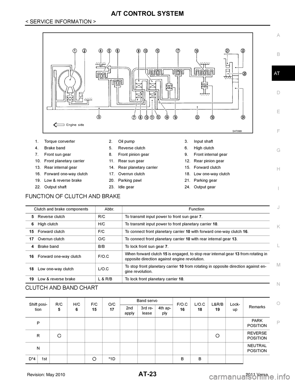
FUNCTION OF CLUTCH AND BRAKE
CLUTCH AND BAND CHART
1. Torque converter 2. Oil pump 3. Input shaft
4. Brake band 5. Reverse clutch 6. High clutch
7. Front sun gear 8. Front pinion gear 9. Front internal gear
10. Front planetary carrier 11. Rear sun gear 12. Rear pinion gear
13. Rear internal gear 14. Rear planetary carrier 15. Forward clutch
16. Forward one-way clutch 17. Overrun clutch 18. Low one-way clutch
19. Low & reverse brake 20. Parking pawl 21. Parking gear
22. Output shaft 23. Idle gear 24. Output gear
SAT998I
Clutch and brake components Abbr. Function
5 Reverse clutch R/C To transmit input power to front sun gear 7 .
6 High clutch H/C To transmit input power to front planetary carrier 10.
15 Forward clutch F/C To connect front planetary carrier 10 with forward one-way clutch 16.
17 Overrun clutch O/C To connect front planetary carrier 10 with rear internal gear 13 .
4 Brake band B/B To lock front sun gear 7.
16 Forward one-way clutch F/O.C When forward clutch 15
is engaged, to stop rear internal gear 13 from rotating in
opposite direction against engine revolution.
18 Low one-way clutch L/O.CTo stop front planetary carrier
10 from rotating in opposite direction against en-
gine revolution.
19 Low & reverse brake L & R/B To lock front planetary carrier 10.
Shift posi-
tion R/C
5 H/C
6 F/C
15 O/C
17 Band servo
F/O.C
16 L/O.C
18 L&R/B
19 Lock-
up Remarks
2nd
apply 3rd re-
lease 4th ap-
ply
P PA R K
POSITION
R REVERSE
POSITION
N NEUTRAL
POSITION
D*4 1st *1DB B
Revision: May 2010 2011 Versa
Page 47 of 3787

AT-30
< SERVICE INFORMATION >
A/T CONTROL SYSTEM
TCM Function
INFOID:0000000005928075
The function of the TCM is to:
• Receive input signals sent from various switches and sensors.
• Determine required line pressure, shifting poi nt, lock-up operation, and engine brake operation.
• Send required output signals to the respective solenoids.
CONTROL SYSTEM OUTLINE
The automatic transaxle senses vehicle operating conditions through various sensors or signals. It always
controls the optimum shift position and reduces shifting and lock-up shocks.
SAT381J
SWITCHES & SENSORS
⇒TCM
⇒ACTUATORS
Transmission range switch
Accelerator pedal position signal
Closed throttle position signal
Wide open throttle position signal
Engine speed signal
A/T fluid temperature sensor
Output speed sensor
Input speed sensor
Vehicle speed signal
Overdrive control switch signal
Stop lamp switch signal Shift control
Line pressure control
Lock-up control
Overrun clutch control
Fail-safe control
Self-diagnosis
CONSULT-III communication
line control
Shift solenoid valve A
Shift solenoid valve B
Overrun clutch solenoid valve
Torque converter clutch solenoid
valve
Line pressure solenoid valve
OD OFF indicator lamp
Revision: May 2010
2011 Versa
Page 48 of 3787

A/T CONTROL SYSTEMAT-31
< SERVICE INFORMATION >
DE
F
G H
I
J
K L
M A
B
AT
N
O P
CONTROL SYSTEM DIAGRAM
CAN CommunicationINFOID:0000000005928076
SYSTEM DESCRIPTION
CAN (Controller Area Network) is a serial communication line for real time application. It is an on-vehicle mul-
tiplex communication line with high data communication speed and excellent error detection ability. Many elec-
tronic control units are equipped onto a vehicle, and each control unit shares information and links with other
control units during operation (not independent). In CAN communication, control units are connected with 2
communication lines (CAN H line, CAN L line) allowing a high rate of information transmission with less wiring.
Each control unit transmits/receives data but selectively reads required data only. For details, refer to LAN-7,
"System Description".
Input/Output Signal of TCMINFOID:0000000005928077
JSDIA1518GB
Control itemLine
pressure control Veh icl e
speed
control Shift
control Lock-up
control Engine
brake
control Fail-safe
function Self-diag-
nostics
function
Input Accelerator pedal position signal
(*5)XXXXX(*3) XX
Output speed sensor X X X X X (*3) X X
Vehicle speed signal (*1) X (*1) X (*1) X (*1) X X
Closed throttle position signal
(*5)(*2) X (*2) X X X(*4) X
Wide open throttle position signal
(*5)(*2) X (*2) X (*4) X
Input speed sensor X XXX X
Engine speed signal XXX X
Transmission range sw itch XXXXX(*3) X(*4) X
Stop lamp switch signal
(*5)XX ( *4 ) X
A/T fluid temperature sensors
(*5)XXXX XX
Overdrive control switch signal
(*5)XXXX (*4) X
TCM power supply voltage signal X XX X
Revision: May 2010 2011 Versa
Page 57 of 3787
AT-40
< SERVICE INFORMATION >
ON BOARD DIAGNOSTIC (OBD) SYSTEM
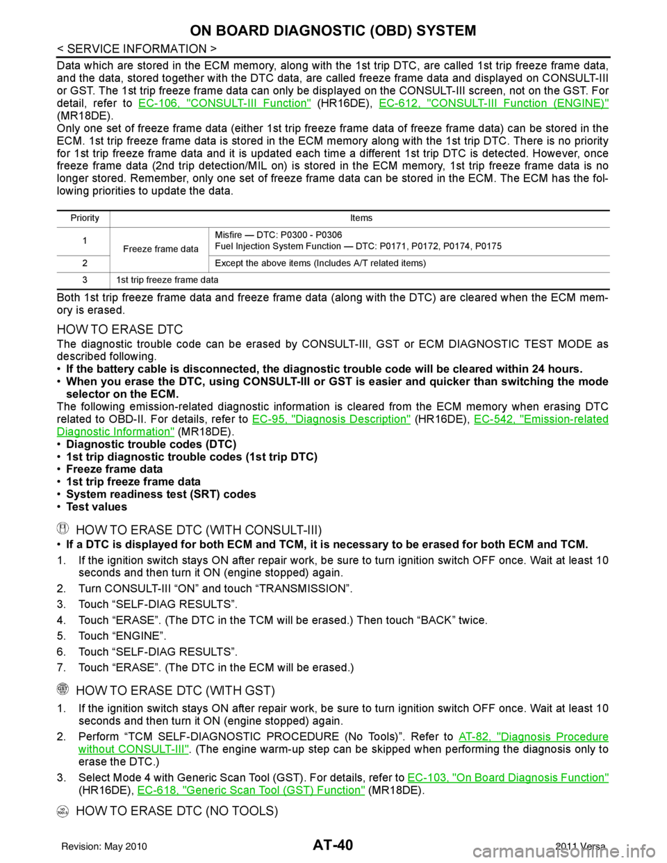
Data which are stored in the ECM memory, along with the 1st trip DTC, are called 1st trip freeze frame data,
and the data, stored together with the DTC data, are called freeze frame data and displayed on CONSULT-III
or GST. The 1st trip freeze frame data can only be disp layed on the CONSULT-III screen, not on the GST. For
detail, refer to EC-106, "
CONSULT-III Function" (HR16DE), EC-612, "CONSULT-III Function (ENGINE)"
(MR18DE).
Only one set of freeze frame data (either 1st trip freeze frame data of freeze frame data) can be stored in the
ECM. 1st trip freeze frame data is stored in the ECM memory along with the 1st trip DTC. There is no priority
for 1st trip freeze frame data and it is updated each time a different 1st trip DTC is detected. However, once
freeze frame data (2nd trip detection/MIL on) is stored in the ECM memory, 1st trip freeze frame data is no
longer stored. Remember, only one set of freeze frame data can be stored in the ECM. The ECM has the fol-
lowing priorities to update the data.
Both 1st trip freeze frame data and freeze frame dat a (along with the DTC) are cleared when the ECM mem-
ory is erased.
HOW TO ERASE DTC
The diagnostic trouble code can be erased by CONSULT- III, GST or ECM DIAGNOSTIC TEST MODE as
described following.
• If the battery cable is disconnected, the diagnosti c trouble code will be cleared within 24 hours.
• When you erase the DTC, using CONSULT-III or GS T is easier and quicker than switching the mode
selector on the ECM.
The following emission-related diagnostic information is cleared from the ECM memory when erasing DTC
related to OBD-II. For details, refer to EC-95, "
Diagnosis Description" (HR16DE), EC-542, "Emission-related
Diagnostic Information" (MR18DE).
• Diagnostic trouble codes (DTC)
• 1st trip diagnostic trou ble codes (1st trip DTC)
• Freeze frame data
• 1st trip freeze frame data
• System readiness test (SRT) codes
• Test values
HOW TO ERASE DTC (WITH CONSULT-III)
•If a DTC is displayed for both ECM and TCM, it is necessary to be erased for both ECM and TCM.
1. If the ignition switch stays ON after repair work, be sure to turn ignition switch OFF once. Wait at least 10 seconds and then turn it ON (engine stopped) again.
2. Turn CONSULT-III “ON” and touch “TRANSMISSION”.
3. Touch “SELF-DIAG RESULTS”.
4. Touch “ERASE”. (The DTC in the TCM will be erased.) Then touch “BACK” twice.
5. Touch “ENGINE”.
6. Touch “SELF-DIAG RESULTS”.
7. Touch “ERASE”. (The DTC in the ECM will be erased.)
HOW TO ERASE DTC (WITH GST)
1. If the ignition switch stays ON after repair work, be sure to turn ignition switch OFF once. Wait at least 10 seconds and then turn it ON (engine stopped) again.
2. Perform “TCM SELF-DIAGNOSTIC PROCEDURE (No Tools)”. Refer to AT-82, "
Diagnosis Procedure
without CONSULT-III". (The engine warm-up step can be skipped when performing the diagnosis only\
to
erase the DTC.)
3. Select Mode 4 with Generic Scan Tool (GST). For details, refer to EC-103, "
On Board Diagnosis Function"
(HR16DE), EC-618, "Generic Scan Tool (GST) Function" (MR18DE).
HOW TO ERASE DTC (NO TOOLS)
Priority Items
1 Freeze frame data Misfire — DTC: P0300 - P0306
Fuel Injection System Function — DTC: P0171, P0172, P0174, P0175
2 Except the above items (Includes A/T related items)
3 1st trip freeze frame data
Revision: May 2010 2011 Versa
Page 58 of 3787
ON BOARD DIAGNOSTIC (OBD) SYSTEMAT-41
< SERVICE INFORMATION >
DE
F
G H
I
J
K L
M A
B
AT
N
O P
The OD OFF indicator lamp is located on the combination meter.
1. If the ignition switch stays ON after repair work, be su re to turn ignition switch OFF once. Wait at least 10
seconds and then turn it ON (engine stopped) again.
2. Perform “TCM SELF-DIAGNOSTIC PR OCEDURE (No Tools)”. Refer to AT-82, "
Diagnosis Procedure
without CONSULT-III". (The engine warm-up step can be skipped when performing the diagnosis only to
erase the DTC.)
3. Perform “OBD-II SELF-DIAGNOSTIC PROCEDURE (No tools)”. Refer to EC-95, "
Diagnosis Description"
(HR16DE), EC-542, "Emission-related Diagnostic Information" (MR18DE).
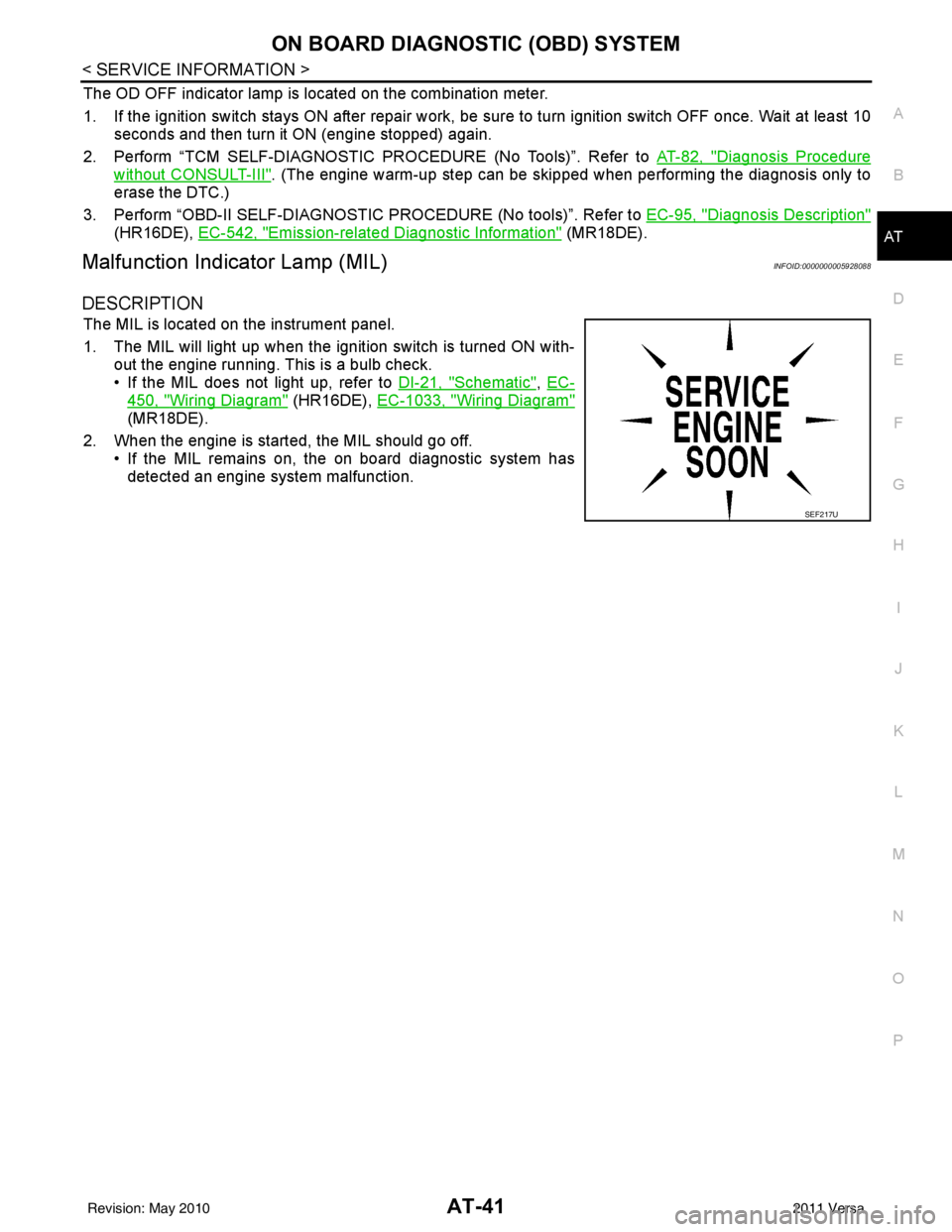
Malfunction Indicator Lamp (MIL)INFOID:0000000005928088
DESCRIPTION
The MIL is located on the instrument panel.
1. The MIL will light up when the ignition switch is turned ON with-
out the engine running. This is a bulb check.
• If the MIL does not light up, refer to DI-21, "
Schematic", EC-
450, "Wiring Diagram" (HR16DE), EC-1033, "Wiring Diagram"
(MR18DE).
2. When the engine is start ed, the MIL should go off.
• If the MIL remains on, the on board diagnostic system has detected an engine system malfunction.
SEF217U
Revision: May 2010 2011 Versa