2011 NISSAN LATIO 237
[x] Cancel search: 237Page 21 of 3787

AT-4
Transmission Range Switch ..................................225
Output Speed Sensor ............................................227
Input Speed Sensor ...............................................228
Differential Side Oil Seal ........................................229
AIR BREATHER HOSE ...................................232
Removal and Installation ..................................... ..232
TRANSAXLE ASSEMBLY ..............................233
Removal and Installation ..................................... ..233
OVERHAUL .................................................... .237
Component .......................................................... ..237
Oil Channel ............................................................250
Location of Adjusting Shims, Needle Bearings and
Thrust Washers .....................................................
253
Location of Snap Rings .........................................255
DISASSEMBLY .............................................. .257
Disassembly ........................................................ ..257
REPAIR FOR COMPONENT PARTS ..............275
Manual Shaft ....................................................... ..275
Oil Pump ................................................................278
Control Valve Assembly ........................................281
Control Valve Upper Body .....................................290
Control Valve Lower Body ................................... ..294
Reverse Clutch ......................................................297
High Clutch ............................................................302
Forward and Overrun Clutches .............................307
Low & Reverse Brake ............................................314
Rear Internal Gear and Forward Clutch Hub .........318
Output Shaft, Output Gear, Idler Gear, Reduction
Pinion Gear and Bearing Retainer .........................
322
Band Servo Piston Assembly ................................331
Final Drive .............................................................337
ASSEMBLY .....................................................344
Assembly (1) ........................................................ ..344
Adjustment (1) (For HR16DE Engine Models) ..... .345
Adjustment (1) (For MR18DE Engine Models) .....349
Assembly (2) .........................................................355
Adjustment (2) .......................................................360
Assembly (3) .........................................................363
SERVICE DATA AND SPECIFICATIONS
(SDS) ................................................................
373
General Specification ........................................... .373
Vehicle Speed at Which Gear Shifting Occurs .....373
Vehicle Speed at When Lock-up Occurs/Releases
.
373
Stall Speed ............................................................374
Line Pressure ........................................................374
Adjusting shims, Needle Bearings, Thrust Wash-
ers and Snap Rings ..............................................
374
Control Valves .......................................................375
Accumulator ..........................................................376
Clutches and Brakes .............................................376
Final Drive .............................................................378
Planetary Carrier ...................................................378
Oil Pump ...............................................................378
Input Shaft .............................................................378
Reduction Pinion Gear ..........................................378
Band Servo ...........................................................378
Output Shaft ..........................................................379
Bearing Retainer ...................................................379
Total End Play ...................................................... .379
Reverse Clutch End Play ......................................379
Removal and Installation .......................................379
Shift Solenoid Valves ........................................... .379
Solenoid Valves ....................................................380
A/T Fluid Temperature Sensor ..............................380
Output Speed Sensor ...........................................380
Dropping Resistor .................................................380
Input Speed Sensor ..............................................380
Revision: May 2010 2011 Versa
Page 34 of 3787
A/T FLUIDAT-17
< SERVICE INFORMATION >
DE
F
G H
I
J
K L
M A
B
AT
N
O P
A/T FLUID
Checking A/T FluidINFOID:0000000005928070
1. Warm up engine.
2. Check for A/T fluid leakage.
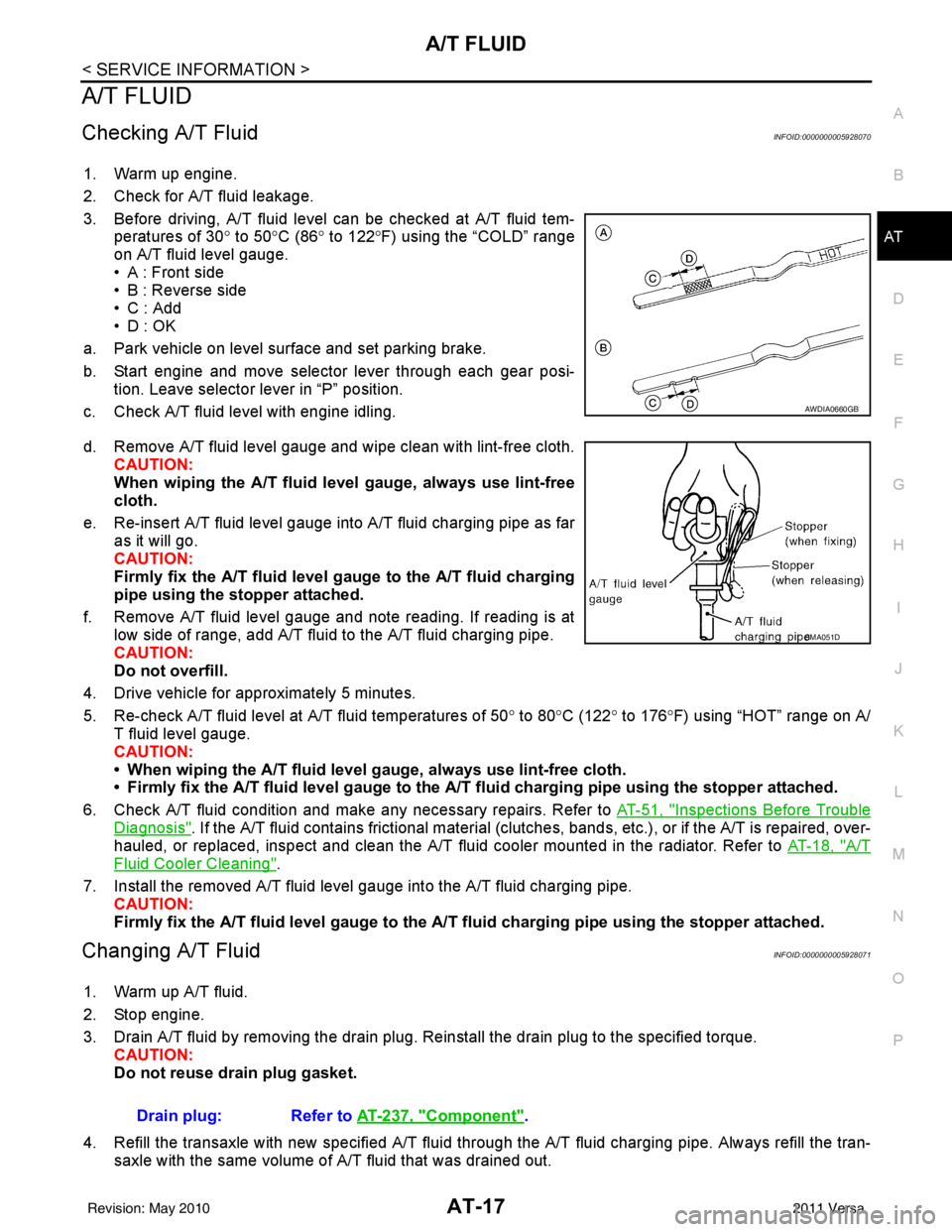
3. Before driving, A/T fluid level can be checked at A/T fluid tem- peratures of 30° to 50°C (86° to 122° F) using the “COLD” range
on A/T fluid level gauge.
• A : Front side
• B : Reverse side
•C : Add
• D : OK
a. Park vehicle on level surface and set parking brake.
b. Start engine and move selector lever through each gear posi- tion. Leave selector lever in “P” position.
c. Check A/T fluid level with engine idling.
d. Remove A/T fluid level gauge and wipe clean with lint-free cloth. CAUTION:
When wiping the A/T fluid l evel gauge, always use lint-free
cloth.
e. Re-insert A/T fluid level gauge into A/T fluid charging pipe as far as it will go.
CAUTION:
Firmly fix the A/T fluid level ga uge to the A/T fluid charging
pipe using the stopper attached.
f. Remove A/T fluid level gauge and note reading. If reading is at low side of range, add A/T fluid to the A/T fluid charging pipe.
CAUTION:
Do not overfill.
4. Drive vehicle for approximately 5 minutes.
5. Re-check A/T fluid level at A/T fluid temperatures of 50° to 80 °C (122° to 176°F) using “HOT” range on A/
T fluid level gauge.
CAUTION:
• When wiping the A/T fluid level gauge, always use lint-free cloth.
• Firmly fix the A/T fluid level ga uge to the A/T fluid charging pipe using the stopper attached.
6. Check A/T fluid condition and make any necessary repairs. Refer to AT-51, "
Inspections Before Trouble
Diagnosis". If the A/T fluid contains frictional material (clutches, bands, etc.), or if the A/T is repaired, over-
hauled, or replaced, inspect and clean the A/T fluid cooler mounted in the radiator. Refer to AT-18, "
A/T
Fluid Cooler Cleaning".
7. Install the removed A/T fluid level gauge into the A/T fluid charging pipe. CAUTION:
Firmly fix the A/T fluid level gaug e to the A/T fluid charging pipe using the stopper attached.
Changing A/T FluidINFOID:0000000005928071
1. Warm up A/T fluid.
2. Stop engine.
3. Drain A/T fluid by removing the drain plug. Re install the drain plug to the specified torque.
CAUTION:
Do not reuse drain plug gasket.
4. Refill the transaxle with new specified A/T fluid through the A/T fluid charging pipe. Always refill the tran- saxle with the same volume of A/T fluid that was drained out.
AWDIA0660GB
SMA051D
Drain plug: Refer to AT-237, "Component".
Revision: May 2010 2011 Versa
Page 185 of 3787
AT-168
< SERVICE INFORMATION >
MAIN POWER SUPPLY AND GROUND CIRCUIT
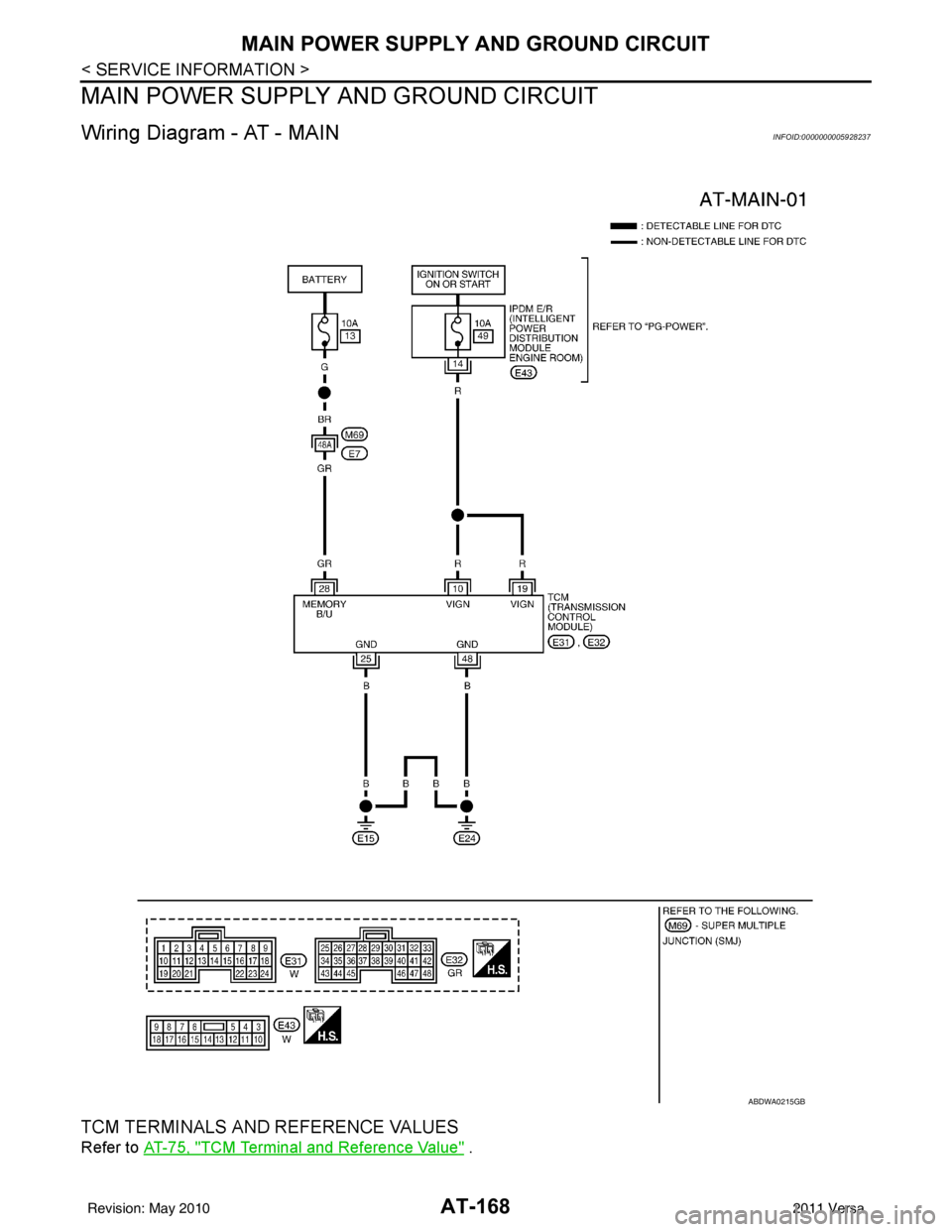
MAIN POWER SUPPLY AND GROUND CIRCUIT
Wiring Diagram - AT - MAININFOID:0000000005928237
TCM TERMINALS AND REFERENCE VALUES
Refer to AT-75, "TCM Terminal and Reference Value" .
ABDWA0215GB
Revision: May 2010 2011 Versa
Page 200 of 3787
TROUBLE DIAGNOSIS FOR SYMPTOMSAT-183
< SERVICE INFORMATION >
DE
F
G H
I
J
K L
M A
B
AT
N
O P
NG >> 1. Check transmission range switch (Refer to test group 1.) again after adjusting transmission
range switch (Refer to AT-225
).
- If OK, INSPECTION END
- If NG, repair or replace transmission range switch. Refer to AT-225, "
Transmission Range
Switch" .
3.CHECK STARTING SYSTEM
Check starting system. Refer to SC-9
.
OK or NG
OK >> INSPECTION END
NG >> Repair or replace damaged parts.
In "P" Position, Vehicle Moves Forward or Backward When PushedINFOID:0000000005928249
SYMPTOM:
Vehicle moves when it is pushed forward or backward with selector lever in “P” position.
DIAGNOSTIC PROCEDURE
1.CHECK A/T POSITION
Check A/T position. Refer to AT-217, "
Checking of A/T Position" .
OK or NG
OK >> GO TO 2.
NG >> Adjust A/T position. Refer to AT-217, "
Adjustment of A/T Position" .
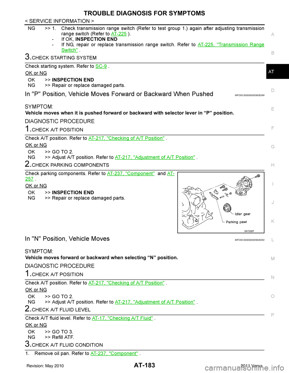
2.CHECK PARKING COMPONENTS
Check parking components. Refer to AT-237, "
Component" and AT-
257 .
OK or NG
OK >> INSPECTION END
NG >> Repair or replace damaged parts.
In "N" Position, Vehicle MovesINFOID:0000000005928250
SYMPTOM:
Vehicle moves forward or backwar d when selecting “N” position.
DIAGNOSTIC PROCEDURE
1.CHECK A/T POSITION
Check A/T position. Refer to AT-217, "
Checking of A/T Position" .
OK or NG
OK >> GO TO 2.
NG >> Adjust A/T position. Refer to AT-217, "
Adjustment of A/T Position" .
2.CHECK A/T FLUID LEVEL
Check A/T fluid level. Refer to AT-17, "
Checking A/T Fluid" .
OK or NG
OK >> GO TO 3.
NG >> Refill ATF.
3.CHECK A/T FLUID CONDITION
1. Remove oil pan. Refer to AT-237, "
Component" .
SAT282F
Revision: May 2010 2011 Versa
Page 203 of 3787
AT-186
< SERVICE INFORMATION >
TROUBLE DIAGNOSIS FOR SYMPTOMS
1. Disassemble A/T. Refer to AT-257, "Disassembly" .
2. Check the following items:
- Low & reverse brake assembly. Refer to AT-314, "
Low & Reverse Brake" .
- Reverse clutch assembly. Refer to AT-297, "
Reverse Clutch" .
OK or NG
OK >> GO TO 6.
NG >> Repair or replace damaged parts.
6.CHECK A/T FLUID CONDITION
1. Remove oil pan. Refer to AT-237, "
Component" .
2. Check A/T fluid condition. Refer to AT-51, "
Inspections Before Trouble Diagnosis" .
OK or NG
OK >> GO TO 8.
NG >> GO TO 7.
7.DETECT MALFUNCTIONING ITEM
1. Disassemble A/T. Refer to AT-257, "
Disassembly" .
2. Check the following items:
- Reverse clutch assembly. Refer to AT-297, "
Reverse Clutch" .
- High clutch assembly. Refer to AT-302, "
High Clutch" .
- Low & reverse brake assembly. Refer to AT-314, "
Low & Reverse Brake" .
- Forward clutch assembly. Refer to AT-307, "
Forward and Overrun Clutches" .
- Overrun clutch assembly. Refer to AT-307, "
Forward and Overrun Clutches" .
OK or NG
OK >> GO TO 8.
NG >> Repair or replace damaged parts.
8.CHECK SYMPTOM
Check again. Refer to AT-56, "
Check at Idle" .
OK or NG
OK >> INSPECTION END
NG >> GO TO 9.
9.CHECK TCM
1. Check TCM input/output signals. Refer to AT-75, "
TCM Terminal and Reference Value" .
2. If NG, recheck TCM pin terminals for damage or loose connection with harness connector.
OK or NG
OK >> INSPECTION END
NG >> Repair or replace damaged parts.
Vehicle Does Not Creep Forward in "D", "2" or "1" PositionINFOID:0000000005928253
SYMPTOM:
Vehicle does not creep forward when selecting “D”, “2” or “1” position.
DIAGNOSTIC PROCEDURE
1.CHECK A/T FLUID LEVEL
Check A/T fluid level. Refer to AT-17, "
Checking A/T Fluid" .
OK or NG
OK >> GO TO 2.
NG >> Refill ATF.
2.CHECK LINE PRESSURE
Check line pressure at idle with selector lever in “D” position. Refer to AT-51, "
Inspections Before Trouble
Diagnosis" .
OK or NG
OK >> GO TO 4.
Revision: May 2010 2011 Versa
Page 204 of 3787
TROUBLE DIAGNOSIS FOR SYMPTOMSAT-187
< SERVICE INFORMATION >
DE
F
G H
I
J
K L
M A
B
AT
N
O P
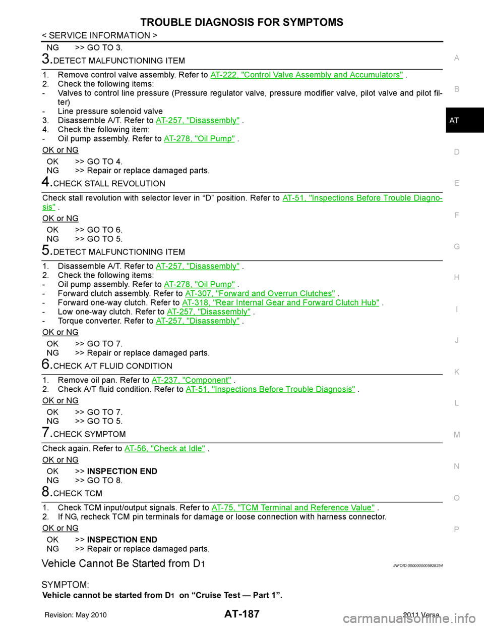
NG >> GO TO 3.
3.DETECT MALFUNCTIONING ITEM
1. Remove control valve assembly. Refer to AT-222, "
Control Valve Assembly and Accumulators" .
2. Check the following items:
- Valves to control line pressure (Pressure regulator valv e, pressure modifier valve, pilot valve and pilot fil-
ter)
- Line pressure solenoid valve
3. Disassemble A/T. Refer to AT-257, "
Disassembly" .
4. Check the following item:
- Oil pump assembly. Refer to AT-278, "
Oil Pump" .
OK or NG
OK >> GO TO 4.
NG >> Repair or replace damaged parts.
4.CHECK STALL REVOLUTION
Check stall revolution with selector lever in “D” position. Refer to AT-51, "
Inspections Before Trouble Diagno-
sis" .
OK or NG
OK >> GO TO 6.
NG >> GO TO 5.
5.DETECT MALFUNCTIONING ITEM
1. Disassemble A/T. Refer to AT-257, "
Disassembly" .
2. Check the following items:
- Oil pump assembly. Refer to AT-278, "
Oil Pump" .
- Forward clutch assembly. Refer to AT-307, "
Forward and Overrun Clutches" .
- Forward one-way clutch. Refer to AT-318, "
Rear Internal Gear and Forward Clutch Hub" .
- Low one-way clutch. Refer to AT-257, "
Disassembly" .
- Torque converter. Refer to AT-257, "
Disassembly" .
OK or NG
OK >> GO TO 7.
NG >> Repair or replace damaged parts.
6.CHECK A/T FLUID CONDITION
1. Remove oil pan. Refer to AT-237, "
Component" .
2. Check A/T fluid condition. Refer to AT-51, "
Inspections Before Trouble Diagnosis" .
OK or NG
OK >> GO TO 7.
NG >> GO TO 5.
7.CHECK SYMPTOM
Check again. Refer to AT-56, "
Check at Idle" .
OK or NG
OK >> INSPECTION END
NG >> GO TO 8.
8.CHECK TCM
1. Check TCM input/output signals. Refer to AT-75, "
TCM Terminal and Reference Value" .
2. If NG, recheck TCM pin terminals for dam age or loose connection with harness connector.
OK or NG
OK >> INSPECTION END
NG >> Repair or replace damaged parts.
Vehicle Cannot Be Started from D1INFOID:0000000005928254
SYMPTOM:
Vehicle cannot be started from D1 on “Cruise Test — Part 1”.
Revision: May 2010 2011 Versa
Page 205 of 3787
AT-188
< SERVICE INFORMATION >
TROUBLE DIAGNOSIS FOR SYMPTOMS
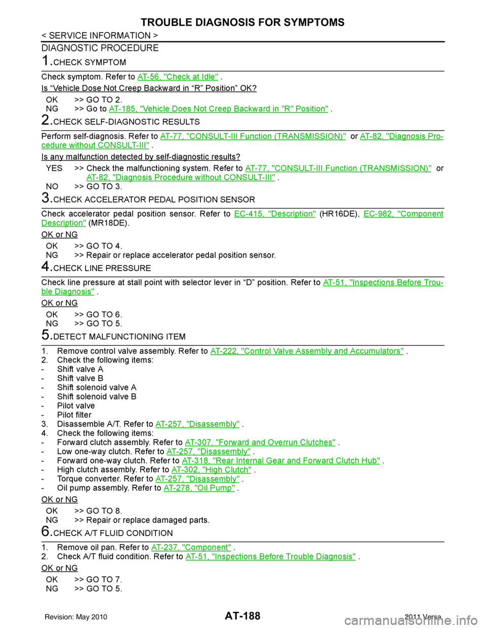
DIAGNOSTIC PROCEDURE
1.CHECK SYMPTOM
Check symptom. Refer to AT-56, "
Check at Idle" .
Is
“Vehicle Dose Not Creep Backward in “R” Position” OK?
OK >> GO TO 2.
NG >> Go to AT-185, "
Vehicle Does Not Creep Backward in "R" Position" .
2.CHECK SELF-DIAGNOSTIC RESULTS
Perform self-diagnosis. Refer to AT-77, "
CONSULT-III Function (TRANSMISSION)" or AT-82, "Diagnosis Pro-
cedure without CONSULT-III" .
Is any malfunction detected by self-diagnostic results?
YES >> Check the malfunctioning system. Refer to AT-77, "CONSULT-III Function (TRANSMISSION)" or
AT-82, "
Diagnosis Procedure without CONSULT-III" .
NO >> GO TO 3.
3.CHECK ACCELERATOR PEDAL POSITION SENSOR
Check accelerator pedal position sensor. Refer to EC-415, "
Description" (HR16DE), EC-982, "Component
Description" (MR18DE).
OK or NG
OK >> GO TO 4.
NG >> Repair or replace accelerator pedal position sensor.
4.CHECK LINE PRESSURE
Check line pressure at stall point with selector lever in “D” position. Refer to AT-51, "
Inspections Before Trou-
ble Diagnosis" .
OK or NG
OK >> GO TO 6.
NG >> GO TO 5.
5.DETECT MALFUNCTIONING ITEM
1. Remove control valve assembly. Refer to AT-222, "
Control Valve Assembly and Accumulators" .
2. Check the following items:
- Shift valve A
- Shift valve B
- Shift solenoid valve A
- Shift solenoid valve B
- Pilot valve
- Pilot filter
3. Disassemble A/T. Refer to AT-257, "
Disassembly" .
4. Check the following items:
- Forward clutch assembly. Refer to AT-307, "
Forward and Overrun Clutches" .
- Low one-way clutch. Refer to AT-257, "
Disassembly" .
- Forward one-way clutch. Refer to AT-318, "
Rear Internal Gear and Forward Clutch Hub" .
- High clutch assembly. Refer to AT-302, "
High Clutch" .
- Torque converter. Refer to AT-257, "
Disassembly" .
- Oil pump assembly. Refer to AT-278, "
Oil Pump" .
OK or NG
OK >> GO TO 8.
NG >> Repair or replace damaged parts.
6.CHECK A/T FLUID CONDITION
1. Remove oil pan. Refer to AT-237, "
Component" .
2. Check A/T fluid condition. Refer to AT-51, "
Inspections Before Trouble Diagnosis" .
OK or NG
OK >> GO TO 7.
NG >> GO TO 5.
Revision: May 2010 2011 Versa
Page 207 of 3787
AT-190
< SERVICE INFORMATION >
TROUBLE DIAGNOSIS FOR SYMPTOMS
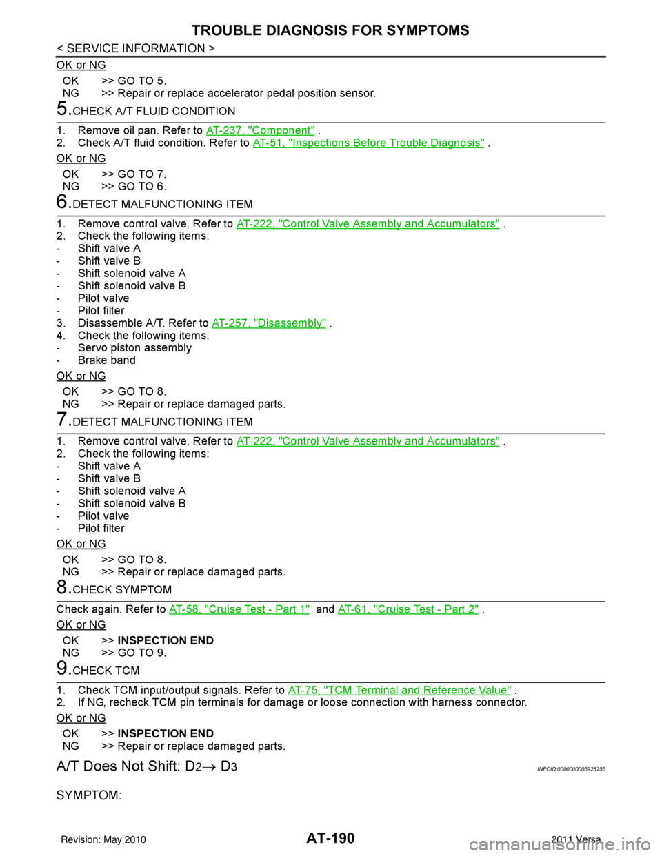
OK or NG
OK >> GO TO 5.
NG >> Repair or replace accelerator pedal position sensor.
5.CHECK A/T FLUID CONDITION
1. Remove oil pan. Refer to AT-237, "
Component" .
2. Check A/T fluid condition. Refer to AT-51, "
Inspections Before Trouble Diagnosis" .
OK or NG
OK >> GO TO 7.
NG >> GO TO 6.
6.DETECT MALFUNCTIONING ITEM
1. Remove control valve. Refer to AT-222, "
Control Valve Assembly and Accumulators" .
2. Check the following items:
- Shift valve A
- Shift valve B
- Shift solenoid valve A
- Shift solenoid valve B
- Pilot valve
- Pilot filter
3. Disassemble A/T. Refer to AT-257, "
Disassembly" .
4. Check the following items:
- Servo piston assembly
- Brake band
OK or NG
OK >> GO TO 8.
NG >> Repair or replace damaged parts.
7.DETECT MALFUNCTIONING ITEM
1. Remove control valve. Refer to AT-222, "
Control Valve Assembly and Accumulators" .
2. Check the following items:
- Shift valve A
- Shift valve B
- Shift solenoid valve A
- Shift solenoid valve B
- Pilot valve
- Pilot filter
OK or NG
OK >> GO TO 8.
NG >> Repair or replace damaged parts.
8.CHECK SYMPTOM
Check again. Refer to AT-58, "
Cruise Test - Part 1" and AT-61, "Cruise Test - Part 2" .
OK or NG
OK >> INSPECTION END
NG >> GO TO 9.
9.CHECK TCM
1. Check TCM input/output signals. Refer to AT-75, "
TCM Terminal and Reference Value" .
2. If NG, recheck TCM pin terminals for damage or loose connection with harness connector.
OK or NG
OK >> INSPECTION END
NG >> Repair or replace damaged parts.
A/T Does Not Shift: D2→ D3INFOID:0000000005928256
SYMPTOM:
Revision: May 2010 2011 Versa