Page 255 of 3787
AT-238
< SERVICE INFORMATION >
OVERHAUL
1. Pinion mate gear thrust washer 2. Pinion mate gear3. Pinion mate shaft
4. Lock pin 5. Side gear 6. Side gear thrust washer
7. Differential side bearing 8. Speedometer drive gear 9. Differential case
10. Final gear 11. Differential side bearing adjusting shim 12. Plug
13. O-ring 14. Bracket 15. RH differential side oil seal
16. Torque converter 17. Converter housing 18. Differential lubricant tube
19. Clip 20. O-ring 21. O-ring
22. Oil pump housing oil seal 23. Oil pump housing 24. Outer gear
25. Inner gear 26. Oil pump cover 27. Seal ring
28. Oil pump assembly
Revision: May 2010 2011 Versa
Page 256 of 3787
OVERHAULAT-239
< SERVICE INFORMATION >
DE
F
G H
I
J
K L
M A
B
AT
N
O P
Without ABS
SCIA7458E
1. Pinion mate gear thrust washer 2. Pinion mate gear 3. Pinion mate shaft
4. Lock pin 5. Side gear 6. Side gear thrust washer
7. Differential side bearing 8. Speedometer drive gear 9. Differential case
10. Final gear 11. Differential side bearing adjusting shim 12. Speedometer pinion
13. O-ring 14. Bracket 15. RH differential side oil seal
16. Torque converter 17. Converter housing 18. Differential lubricant tube
Revision: May 2010 2011 Versa
Page 261 of 3787
AT-244
< SERVICE INFORMATION >
OVERHAUL
With ABS
SCIA7956E
1. Pinion mate gear thrust washer 2. Pinion mate gear3. Pinion mate shaft
4. Lock pin 5. Side gear 6. Side gear thrust washer
7. Differential side bearing 8. Speedometer drive gear9. Differential case
10. Final gear 11. Differential side bearing adjusting
shim 12. Plug
13. O-ring 14. Bracket 15. RH differential side oil seal
16. Torque converter 17. Converter housing18. Differential lubricant tube
Revision: May 2010 2011 Versa
Page 263 of 3787
AT-246
< SERVICE INFORMATION >
OVERHAUL
7. Differential side bearing8. Speedometer drive gear9. Differential case
10. Final gear 11. Differential side bearing adjusting
shim 12. Speedometer pinion
13. O-ring 14. Bracket 15. RH differential side oil seal
16. Torque converter 17. Converter housing18. Differential lubricant tube
19. Clip 20. O-ring 21. O-ring
22. Oil pump housing oil seal 23. Oil pump housing24. Outer gear
25. Inner gear 26. Oil pump cover27. Seal ring
28. Oil pump assembly
Revision: May 2010 2011 Versa
Page 274 of 3787
DISASSEMBLYAT-257
< SERVICE INFORMATION >
DE
F
G H
I
J
K L
M A
B
AT
N
O P
DISASSEMBLY
DisassemblyINFOID:0000000005928289
1. Drain ATF through drain hole.
2. Remove drain plug gasket from drain plug.
3. Remove torque converter.
4. Check torque converter one-way clutch using check tool as shown.
a. Insert check tool into groove of bearing support built into one- way clutch outer race.
b. When fixing bearing support with check tool, rotate one-way clutch spline using screwdriver.
c. Check that inner race rotates clockwise only. If not, replace torque converter assembly.
SCIA0003E
SAT008D
SAT009D
Revision: May 2010 2011 Versa
Page 295 of 3787
AT-278
< SERVICE INFORMATION >
REPAIR FOR COMPONENT PARTS
9. Install detent spring on transaxle case.
10. Tighten detent spring bolt to the specified torque. Refer to AT-
275, "Manual Shaft".
Oil PumpINFOID:0000000005928291
COMPONENTS
DISASSEMBLY
1. Remove seal rings (1) from oil pump assembly (2).
SAT042F
1. Oil pump housing oil seal 2. Oil pump housing 3. Outer gear
4. Inner gear 5. Oil pump cover6. Seal ring
SCIA5908J
SCIA7016E
Revision: May 2010 2011 Versa
Page 298 of 3787

REPAIR FOR COMPONENT PARTSAT-281
< SERVICE INFORMATION >
DE
F
G H
I
J
K L
M A
B
AT
N
O P
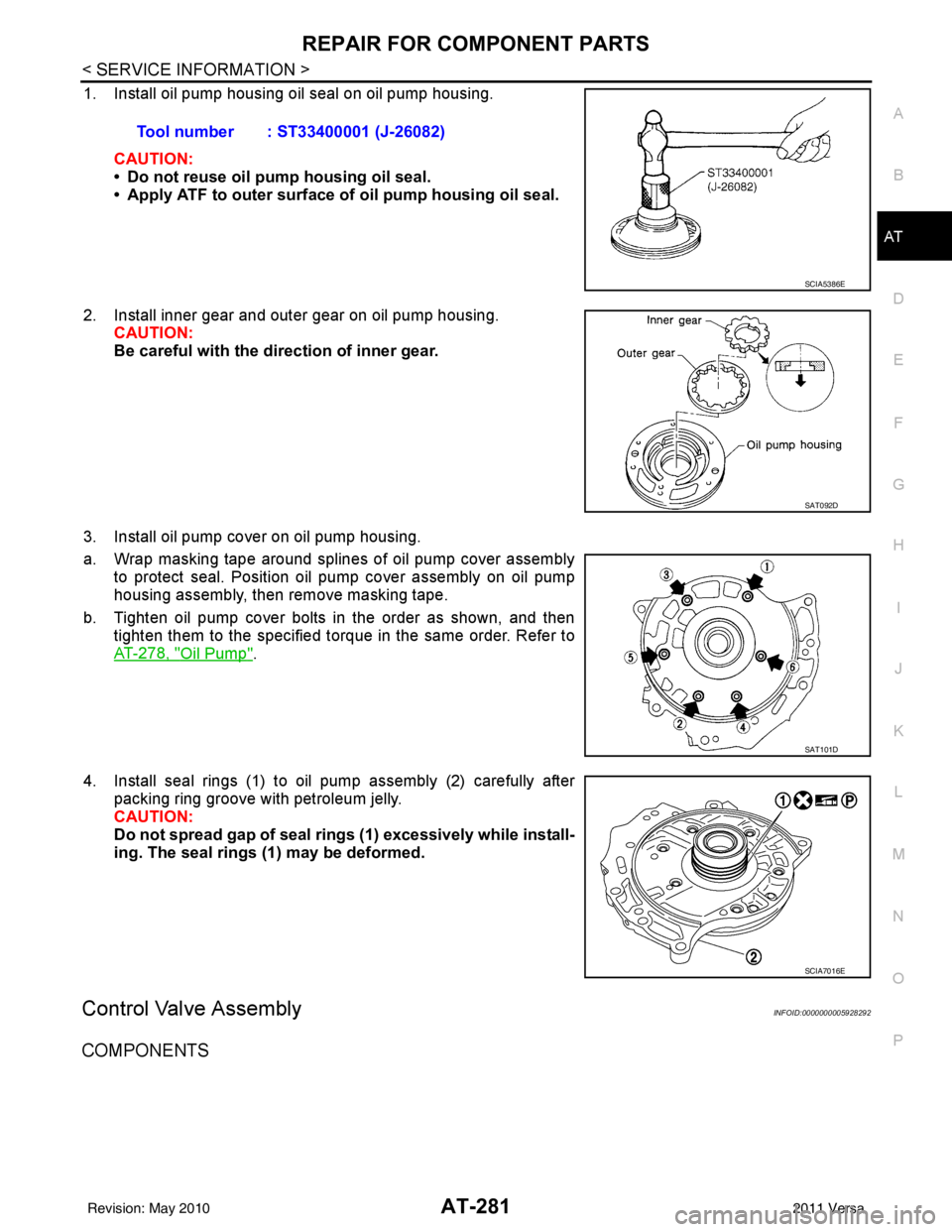
1. Install oil pump housing oil seal on oil pump housing.
CAUTION:
• Do not reuse oil pump housing oil seal.
• Apply ATF to outer surface of oil pump housing oil seal.
2. Install inner gear and outer gear on oil pump housing. CAUTION:
Be careful with the di rection of inner gear.
3. Install oil pump cover on oil pump housing.
a. Wrap masking tape around splines of oil pump cover assembly to protect seal. Position oil pump cover assembly on oil pump
housing assembly, then remove masking tape.
b. Tighten oil pump cover bolts in the order as shown, and then tighten them to the specified torque in the same order. Refer to
AT-278, "
Oil Pump".
4. Install seal rings (1) to oil pump assembly (2) carefully after packing ring groove with petroleum jelly.
CAUTION:
Do not spread gap of seal ri ngs (1) excessively while install-
ing. The seal rings (1) may be deformed.
Control Valve AssemblyINFOID:0000000005928292
COMPONENTS
Tool number : ST33400001 (J-26082)
SCIA5386E
SAT092D
SAT101D
SCIA7016E
Revision: May 2010 2011 Versa
Page 299 of 3787
AT-282
< SERVICE INFORMATION >
REPAIR FOR COMPONENT PARTS
DISASSEMBLY
Place control valve assembly with control valve upper body (1) side
down. Remove bolts (A) to (G), reamer bolts (F), nuts and support
plates (4) according to the following procedures. Separate control
valve upper body (1), control valve inter body (2) and control valve
lower body (3).
1. Pilot filter2. Control valve upper body 3. Steel ball
4. Separating plate 5. Control valve inter body 6. Steel ball
7. Support plate 8. Separating plate9. Control valve lower body
10. Line pressure relief valve spring 11. Check ball 12. Torque converter pressure
holding spring
13. Solenoid valve assembly 14. Terminal body 15. O-ring
16. O-ring 17. O-ring18. Oil strainer
SCIA8407J
SCIA7058E
Revision: May 2010 2011 Versa